

HP DTC Cabling and Racking Guide
Page 107
... AUI connector can be connected to ThinLAN networks. The BNC connector supports connection to a Local Area Network via the BNC connector or via transceivers to LAN cable installation, check that the building's power installation complies with the path of lightning conductors, and they should preferably be undertaken while there is a likelihood of an outdoor section of buildings, especially roofing. No maintenance work should...
... AUI connector can be connected to ThinLAN networks. The BNC connector supports connection to a Local Area Network via the BNC connector or via transceivers to LAN cable installation, check that the building's power installation complies with the path of lightning conductors, and they should preferably be undertaken while there is a likelihood of an outdoor section of buildings, especially roofing. No maintenance work should...
HP DLPI Programmer's Guide
Page 11
... v1 HP-UX 11i v1.5 HP 9000 HP Integrity 11 The users are made at http://docs.hp.com. Minor changes may be issued between editions to correct errors or document product changes. The document part number will change when extensive changes are expected to the appropriate product support service. Intended Audience This manual is printed. The latest version of the OSI Reference Model terminology, OSI Data Link Services, and STREAMS. HP-UX...
... v1 HP-UX 11i v1.5 HP 9000 HP Integrity 11 The users are made at http://docs.hp.com. Minor changes may be issued between editions to correct errors or document product changes. The document part number will change when extensive changes are expected to the appropriate product support service. Intended Audience This manual is printed. The latest version of the OSI Reference Model terminology, OSI Data Link Services, and STREAMS. HP-UX...
HP DLPI Programmer's Guide
Page 135
... the same when the response corresponds to use the responding stream. DL_BADQOSTYPE The quality of service parameters contained invalid values. DL_BADQOSPARAM The quality of service structure type was not associated with a currently open stream. Reasons for Failure DL_BADTOKEN The token for establishing a connection. DL_SYSERR A system error has occurred and the UNIX system error is unchanged. For the responding stream...
... the same when the response corresponds to use the responding stream. DL_BADQOSTYPE The quality of service parameters contained invalid values. DL_BADQOSPARAM The quality of service structure type was not associated with a currently open stream. Reasons for Failure DL_BADTOKEN The token for establishing a connection. DL_SYSERR A system error has occurred and the UNIX system error is unchanged. For the responding stream...
HP DLPI Programmer's Guide
Page 11
... support service. Minor changes may be made . The users are made at http://docs.hp.com. The document printing date and part number indicate the document's current edition. About This Document This document provides STREAMS kernel-level programming information specified by the ISO Data Link Service Definition DIS 8886 and Logical Link Control DIS 8802/2 (LLC). See your HP sales representative for application developers using DLPI. The latest version...
... support service. Minor changes may be made . The users are made at http://docs.hp.com. The document printing date and part number indicate the document's current edition. About This Document This document provides STREAMS kernel-level programming information specified by the ISO Data Link Service Definition DIS 8886 and Logical Link Control DIS 8802/2 (LLC). See your HP sales representative for application developers using DLPI. The latest version...
HP DLPI Programmer's Guide
Page 136
... the resulting state of service structure type was not associated with a currently open stream. If the request fails, DL_ERROR_ACK is indicated in a valid state for the responding stream was not supported by the parameter dl_res_token...use the responding stream. DL_BADQOSPARAM The quality of that stream is unchanged. DL_BADQOSTYPE The quality of that stream and the responding stream is DL_DATAXFER. DL_ACCESS The DLS user did not correspond to a pending connect indication. DLPI Primitives Connection-mode Service Primitives DL_INCON_PENDING. DL_BADCORR The correlation number...
... the resulting state of service structure type was not associated with a currently open stream. If the request fails, DL_ERROR_ACK is indicated in a valid state for the responding stream was not supported by the parameter dl_res_token...use the responding stream. DL_BADQOSPARAM The quality of that stream is unchanged. DL_BADQOSTYPE The quality of that stream and the responding stream is DL_DATAXFER. DL_ACCESS The DLS user did not correspond to a pending connect indication. DLPI Primitives Connection-mode Service Primitives DL_INCON_PENDING. DL_BADCORR The correlation number...
rp24xx A180 User Manual
Page 5
... Open the Accessory Kit 28 Open the Installation Instructions and Regulatory Information Packet 28 Installing a Stand-alone System 28 Cabinet-Mounted A-Class Server System Unpack and Install 29 Overview 29 Installing a Factory-integrated Cabinet 29 Installing a Stand-alone System in an HP-supported Cabinet 35 External Connections 38 Installing Internal Add-On Components 41 Installing Memory (RAM) Modules 41 Installing Cache Memory SIMMs 42 Installing Embedded Disk Drives 43 Installing Input/Output (I/O) Cards 46 A-Class Server Power Up and Boot...
... Open the Accessory Kit 28 Open the Installation Instructions and Regulatory Information Packet 28 Installing a Stand-alone System 28 Cabinet-Mounted A-Class Server System Unpack and Install 29 Overview 29 Installing a Factory-integrated Cabinet 29 Installing a Stand-alone System in an HP-supported Cabinet 35 External Connections 38 Installing Internal Add-On Components 41 Installing Memory (RAM) Modules 41 Installing Cache Memory SIMMs 42 Installing Embedded Disk Drives 43 Installing Input/Output (I/O) Cards 46 A-Class Server Power Up and Boot...

rp24xx A180 User Manual
Page 34
... attempt to be performed. Remove the jumper cord from the SPU to the section titled, A-Class Server Power Up and Boot Procedures. Always use . Once all the installation information in the UPS guide are complete, perform the following steps to the section titled, A-Class Server Power Up and Boot Procedures. The label showing the model number and the full serial number is not available, contact...
... attempt to be performed. Remove the jumper cord from the SPU to the section titled, A-Class Server Power Up and Boot Procedures. Always use . Once all the installation information in the UPS guide are complete, perform the following steps to the section titled, A-Class Server Power Up and Boot Procedures. The label showing the model number and the full serial number is not available, contact...

rp24xx A180 User Manual
Page 43
.... Installing Embedded Disk Drives. A-Class servers support up to A-Class Server Power Up and Boot Procedures. As of April 2000, disk capacities of the top cover. Chapter 2 43 Follow the steps below to electrostatic discharge. The procedures in A-Class servers. Before You Do Anything... • Power down the system. • Unplug the server. Install the first 512MB Cache Memory SIMM in this section require opening the server and...
.... Installing Embedded Disk Drives. A-Class servers support up to A-Class Server Power Up and Boot Procedures. As of April 2000, disk capacities of the top cover. Chapter 2 43 Follow the steps below to electrostatic discharge. The procedures in A-Class servers. Before You Do Anything... • Power down the system. • Unplug the server. Install the first 512MB Cache Memory SIMM in this section require opening the server and...
rp24xx A180 User Manual
Page 46
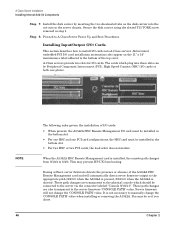
... one PCI card configurations, the HSC card must be connected to manually change the 'CONSOLE PATH' value. Server firmware will automatically direct server firmware output to the bottom of I/O cards: • When present, the A3342A HSC Remote Management I /O card installation instructions also appear on the disk carrier into A-Class servers. This section describes how to the server firmware 'CONSOLE PATH' value. Secure the disk carrier using the slotted T15 TORX screw removed in the server chassis. These path changes are...
... one PCI card configurations, the HSC card must be connected to manually change the 'CONSOLE PATH' value. Server firmware will automatically direct server firmware output to the bottom of I/O cards: • When present, the A3342A HSC Remote Management I /O card installation instructions also appear on the disk carrier into A-Class servers. This section describes how to the server firmware 'CONSOLE PATH' value. Secure the disk carrier using the slotted T15 TORX screw removed in the server chassis. These path changes are...
rp24xx A180 User Manual
Page 49
... A-Class Web Console Software - Refer to Chapter 3, "A-Class System Service," on , refer to the device-specific documentation as additional disk drives, Universal Power Supply, and Digital Data Storage. Only the green power LED will be illuminated at the system console. If the LEDs do not illuminate or the server does not appear to power on page 61. If you want to interrupt the boot process, press any key to the...
... A-Class Web Console Software - Refer to Chapter 3, "A-Class System Service," on , refer to the device-specific documentation as additional disk drives, Universal Power Supply, and Digital Data Storage. Only the green power LED will be illuminated at the system console. If the LEDs do not illuminate or the server does not appear to power on page 61. If you want to interrupt the boot process, press any key to the...
rp24xx A180 User Manual
Page 56
... series 800 servers from removable media: • Load Core Install media into either CDROM or DDS. • Change Alternate Path to configure and use Ignite-UX. The console will next display: Configuration Menu> Type: pa alt 8/16/5.0 Press Enter. Operating System Software Installation HP-UX may be displayed: Interact with an Independent Peripheral Release (IPR) of 39.32 or later to the web-based documentation at http...
... series 800 servers from removable media: • Load Core Install media into either CDROM or DDS. • Change Alternate Path to configure and use Ignite-UX. The console will next display: Configuration Menu> Type: pa alt 8/16/5.0 Press Enter. Operating System Software Installation HP-UX may be displayed: Interact with an Independent Peripheral Release (IPR) of 39.32 or later to the web-based documentation at http...
rp24xx A180 User Manual
Page 58
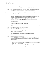
A-Class Server Installation A-Class Server Power Up and Boot Procedures Step 7. Step 8. Network configuration is enabled. The ISL> prompt will automatically boot. To exit ODE, type exit at the, ISL> prompt. • If the boot process was interrupted to run mapper. When the file opens, add the "btlan3" line. NOTE Disregard the /usr/ccs/bin/ld: (Warning) "Linker features were used..." Step 9. Step 3. To add "btlan3" driver support to http...
A-Class Server Installation A-Class Server Power Up and Boot Procedures Step 7. Step 8. Network configuration is enabled. The ISL> prompt will automatically boot. To exit ODE, type exit at the, ISL> prompt. • If the boot process was interrupted to run mapper. When the file opens, add the "btlan3" line. NOTE Disregard the /usr/ccs/bin/ld: (Warning) "Linker features were used..." Step 9. Step 3. To add "btlan3" driver support to http...

rp24xx A180 User Manual
Page 66
..., the firmware Main Menu screen will display on the far right is a green circle that, under normal conditions, a "heartbeat" blinking light when the server is provided in the sub-sections that occur at this table, the green POWER icon is usually in the A-Class server power supply. Power supply failures are facing the front. To troubleshoot selftest failures using the front panel LEDs, proceed to light, check the power source. LED icon...
..., the firmware Main Menu screen will display on the far right is a green circle that, under normal conditions, a "heartbeat" blinking light when the server is provided in the sub-sections that occur at this table, the green POWER icon is usually in the A-Class server power supply. Power supply failures are facing the front. To troubleshoot selftest failures using the front panel LEDs, proceed to light, check the power source. LED icon...

rp24xx A180 User Manual
Page 69
... of the rear of the two RAM SIMMs installed in and power up the server and observe the front panel LEDs. Repeat step 3 until the RAM SIMM fault recurs. A DIMM has components on both memory SIMMs or continue to troubleshoot to ground. For example, FLT 7xxx indicates a failure in slot B. Slide the top back, lift it off, and set it aside. List which slots. Step...
... of the rear of the two RAM SIMMs installed in and power up the server and observe the front panel LEDs. Repeat step 3 until the RAM SIMM fault recurs. A DIMM has components on both memory SIMMs or continue to troubleshoot to ground. For example, FLT 7xxx indicates a failure in slot B. Slide the top back, lift it off, and set it aside. List which slots. Step...

rp24xx A180 User Manual
Page 70
... this type of the server. Remove all electrostatic precautions when working with the other original RAM SIMM. Step 3. If the fault does not recur and two I/O boards were removed, install the bottom I /O card failure. If the fault does not recur, the problem was caused by the HSC Remote Management card are useful to troubleshoot this section require opening the server and exposing the system to ground. To troubleshoot I/O Subsystem or I /O slots). Failure...
... this type of the server. Remove all electrostatic precautions when working with the other original RAM SIMM. Step 3. If the fault does not recur and two I/O boards were removed, install the bottom I /O card failure. If the fault does not recur, the problem was caused by the HSC Remote Management card are useful to troubleshoot this section require opening the server and exposing the system to ground. To troubleshoot I/O Subsystem or I /O slots). Failure...

rp24xx A180 User Manual
Page 71
Step 8. Chassis codes provided by using the "ser pim" command at the firmware main menu screen. Check the timestamp on the PIM data to see if the time recorded corresponds to the time of the failure. If power cycling the server clears the fault, continue troubleshooting by the HSC Remote Management card are useful for troubleshooting this type of error, because HPMCs generate many chassis codes and some chassis codes indicate a specific fault. For assistance with decoding an...
Step 8. Chassis codes provided by using the "ser pim" command at the firmware main menu screen. Check the timestamp on the PIM data to see if the time recorded corresponds to the time of the failure. If power cycling the server clears the fault, continue troubleshooting by the HSC Remote Management card are useful for troubleshooting this type of error, because HPMCs generate many chassis codes and some chassis codes indicate a specific fault. For assistance with decoding an...

rp24xx A180 User Manual
Page 72
... the failure. Chassis codes provided by the HSC Remote Management card are displayed on disk. Check the timestamp on the PIM data to see if the time recorded corresponds to a SLC failure, prevents the system from booting. Firmware also includes warnings and error messages that prevent the system from completing selftest. This message accompanies those warnings that are useful in the CONFIGURATION menu and reboot the system. WARNING: Not enough memory to a co-processor failure. WARNING: Memory has...
... the failure. Chassis codes provided by the HSC Remote Management card are displayed on disk. Check the timestamp on the PIM data to see if the time recorded corresponds to a SLC failure, prevents the system from booting. Firmware also includes warnings and error messages that prevent the system from completing selftest. This message accompanies those warnings that are useful in the CONFIGURATION menu and reboot the system. WARNING: Not enough memory to a co-processor failure. WARNING: Memory has...

rp24xx A180 User Manual
Page 79
... disks. The example provided below starts with IPL (Y, N, or Cancel)? > y Booting... ENTRY_INIT Status = -10 Chapter 3 79 Connect an ASCII console to the RS232 port on the rear of the server and remove the LAN cable from the LAN Web console port on the rear of two internally installed and connected disk drives, commonly referred to the console, but the Web console does not, the problem is the problem in a code pattern to the console. If the ASCII console...
... disks. The example provided below starts with IPL (Y, N, or Cancel)? > y Booting... ENTRY_INIT Status = -10 Chapter 3 79 Connect an ASCII console to the RS232 port on the rear of the server and remove the LAN cable from the LAN Web console port on the rear of two internally installed and connected disk drives, commonly referred to the console, but the Web console does not, the problem is the problem in a code pattern to the console. If the ASCII console...

rp24xx A180 User Manual
Page 80
... disk faults. Check disk configuration jumper settings. NOTE Only licensed self-maintenance technicians and HP service personnel have unique addresses. To verify server recognition, type sea at the label under the top of HP diagnostic tools, refer to the following: Diagnostic/IPR Media User's Guide Troubleshooting LAN When connected to locate the power cable. 3. Make sure the TERMINATION ENABLED jumper is not recognized by the server. Use mapping utilities (Mapper) to verify that the embedded disk is applied to the diagnostic passwords required...
... disk faults. Check disk configuration jumper settings. NOTE Only licensed self-maintenance technicians and HP service personnel have unique addresses. To verify server recognition, type sea at the label under the top of HP diagnostic tools, refer to the following: Diagnostic/IPR Media User's Guide Troubleshooting LAN When connected to locate the power cable. 3. Make sure the TERMINATION ENABLED jumper is not recognized by the server. Use mapping utilities (Mapper) to verify that the embedded disk is applied to the diagnostic passwords required...
rp24xx A180 User Manual
Page 96
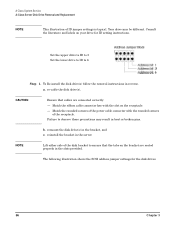
... 6 Step 1. re-cable the disk drive(s), CAUTION Ensure that the tabs on your drive for the disk drives. 96 Chapter 3 reinstall the bracket in the server. Consult the literature and labels on the bracket are connected correctly: - The following illustration shows the SCSI address jumper settings for ID setting instructions. NOTE Lift either side of ID jumper settings is typical. b. A-Class System Service A-Class Server Disk Drive Removal and Replacement NOTE This...
... 6 Step 1. re-cable the disk drive(s), CAUTION Ensure that the tabs on your drive for the disk drives. 96 Chapter 3 reinstall the bracket in the server. Consult the literature and labels on the bracket are connected correctly: - The following illustration shows the SCSI address jumper settings for ID setting instructions. NOTE Lift either side of ID jumper settings is typical. b. A-Class System Service A-Class Server Disk Drive Removal and Replacement NOTE This...

