
Maintenance and Service Guide
Page 8
... Hardware Diagnostics (UEFI 68 HP Support Assistant (HPSA 70 HP BIOS Configuration Utility (BCU 71 HP Image Diagnostic Tool 71 HP Thermal Monitor 71 Non HP diagnostics tools 71 viii Perform a visual inspection of hardware 67 4. Battery ...32 Solid-state drive (M.2) ...33 WLAN module ...35 Memory module ...37 RTC battery ...39 6 Removal and replacement procedures for authorized service...
... Hardware Diagnostics (UEFI 68 HP Support Assistant (HPSA 70 HP BIOS Configuration Utility (BCU 71 HP Image Diagnostic Tool 71 HP Thermal Monitor 71 Non HP diagnostics tools 71 viii Perform a visual inspection of hardware 67 4. Battery ...32 Solid-state drive (M.2) ...33 WLAN module ...35 Memory module ...37 RTC battery ...39 6 Removal and replacement procedures for authorized service...
Maintenance and Service Guide
Page 9
... lights 75 Resolve the issue ...76 8. Soft reset (Default Settings 77 10. Replace the system board 79 Verify solution ...80 Helpful Hints ...80 At startup ...80 During operation ...81 Consulting with HP Service ...82 Common issues and possible solutions ...82 Power-on issues ...82 No Power... ...82 Intermittent power-on, shutdown, reboot 84 AC adapter issue ...85 Battery not recognized, not charging 86 Battery discharges too fast 87 Burnt smell ...88...
... lights 75 Resolve the issue ...76 8. Soft reset (Default Settings 77 10. Replace the system board 79 Verify solution ...80 Helpful Hints ...80 At startup ...80 During operation ...81 Consulting with HP Service ...82 Common issues and possible solutions ...82 Power-on issues ...82 No Power... ...82 Intermittent power-on, shutdown, reboot 84 AC adapter issue ...85 Battery not recognized, not charging 86 Battery discharges too fast 87 Burnt smell ...88...

Maintenance and Service Guide
Page 19
... (RHEL) 7.x 64bit Web-only support: ● Windows 10 Enterprise ● Windows 7 Enterprise 64-bit, Service Pack 1 ● Windows 8.1 ● Red Hat Enterprise Linux End user replaceable parts: ● AC adapter ● Battery (system) ● Memory modules ● Solid-state drive ● WLAN module 5
... (RHEL) 7.x 64bit Web-only support: ● Windows 10 Enterprise ● Windows 7 Enterprise 64-bit, Service Pack 1 ● Windows 8.1 ● Red Hat Enterprise Linux End user replaceable parts: ● AC adapter ● Battery (system) ● Memory modules ● Solid-state drive ● WLAN module 5

Maintenance and Service Guide
Page 46
... the computer through the operating system. 2. To reduce potential safety issues, use only the user-replaceable battery provided with the computer, a replacement battery provided by unplugging the power cord from the computer. 3. To prevent loss of information. Remove the battery from HP. Disconnect all external devices from the system board (1). 2. Reverse this procedure to the computer...
... the computer through the operating system. 2. To reduce potential safety issues, use only the user-replaceable battery provided with the computer, a replacement battery provided by unplugging the power cord from the computer. 3. To prevent loss of information. Remove the battery from HP. Disconnect all external devices from the system board (1). 2. Reverse this procedure to the computer...

Maintenance and Service Guide
Page 47
...it down through the operating system. 2. NOTE: If the module springs up when the screw is removed and the module springs up. 2. Component replacement procedures 33 Remove the bottom cover (see Service door on page 30). 5. Turn off or in Bracket Kit, spare part number 840966-001) ...001 840949-001 930462-001 922235-001 846386-001 840966-001 (Bracket Kit) Before removing the solid-state drive, follow these steps: 1. Remove the battery (see Battery on page 32). Remove the solid-state drive: 1. Solid-state drive (M.2) Description 1-TB, Z Turbo drive PCIe 512-GB, Z Turbo Drive, ...
...it down through the operating system. 2. NOTE: If the module springs up when the screw is removed and the module springs up. 2. Component replacement procedures 33 Remove the bottom cover (see Service door on page 30). 5. Turn off or in Bracket Kit, spare part number 840966-001) ...001 840949-001 930462-001 922235-001 846386-001 840966-001 (Bracket Kit) Before removing the solid-state drive, follow these steps: 1. Remove the battery (see Battery on page 32). Remove the solid-state drive: 1. Solid-state drive (M.2) Description 1-TB, Z Turbo drive PCIe 512-GB, Z Turbo Drive, ...

Maintenance and Service Guide
Page 49
...6. Disconnect the power from the computer by the governmental agency that secures the WLAN module to the system board. (The WLAN module tilts up.) Component replacement procedures 35 Turn off or in your country or region. The WLAN antenna cable labeled "2" connects to the WLAN module "Main" terminal labeled "1". If ...you are unsure whether the computer is off the computer. Disconnect the battery (see Battery on the WLAN module. Disconnect the WLAN antenna cables (1) from the terminals on page 32).
...6. Disconnect the power from the computer by the governmental agency that secures the WLAN module to the system board. (The WLAN module tilts up.) Component replacement procedures 35 Turn off or in your country or region. The WLAN antenna cable labeled "2" connects to the WLAN module "Main" terminal labeled "1". If ...you are unsure whether the computer is off the computer. Disconnect the battery (see Battery on the WLAN module. Disconnect the WLAN antenna cables (1) from the terminals on page 32).

Maintenance and Service Guide
Page 51
... information, and then click Search. 4. Before removing a memory module, follow the on each side of the memory module slot to www.hp.com. 2. Select the operating system, and then click Next. 6. If you update the computer to installing new memory may result in ...Remove the memory module: 1. Navigate to release the memory module. (The memory module tilts up.) Component replacement procedures 37 Click Support & Drivers > Drivers & Software. 3. Remove the service door (see Battery on page 31). 6. Turn off or in various system problems. To update BIOS: 1. CAUTION: Failure ...
... information, and then click Search. 4. Before removing a memory module, follow the on each side of the memory module slot to www.hp.com. 2. Select the operating system, and then click Next. 6. If you update the computer to installing new memory may result in ...Remove the memory module: 1. Navigate to release the memory module. (The memory module tilts up.) Component replacement procedures 37 Click Support & Drivers > Drivers & Software. 3. Remove the service door (see Battery on page 31). 6. Turn off or in various system problems. To update BIOS: 1. CAUTION: Failure ...

Maintenance and Service Guide
Page 53
... the power cord from the system board. 2. Detach the RTC battery (2) from the computer. 4. Component replacement procedures 39 RTC battery Description RTC battery (includes cable and double-sided adhesive) Spare part number 840953-001 Before removing the RTC battery, follow these steps: 1. Disconnect the RTC battery cable (1) from the computer. 3. If you are unsure whether the...
... the power cord from the system board. 2. Detach the RTC battery (2) from the computer. 4. Component replacement procedures 39 RTC battery Description RTC battery (includes cable and double-sided adhesive) Spare part number 840953-001 Before removing the RTC battery, follow these steps: 1. Disconnect the RTC battery cable (1) from the computer. 3. If you are unsure whether the...

Maintenance and Service Guide
Page 54
... graphics memory (4 + 4E) Thermal module for authorized service provider parts Remove the service door (see Service door on page 32). Disconnect the battery (see Bottom cover on , and then shut it down through the operating system. 2. Disconnect the cable for each screw size and location during...Loosen the six captive screws (discrete models) or three captive screws (UMA models) in Hibernation, turn the computer on page 31). 6. Component replacement procedures There are unsure whether the computer is off the computer. If you are as many as 74 screws that must be accessed only by...
... graphics memory (4 + 4E) Thermal module for authorized service provider parts Remove the service door (see Service door on page 32). Disconnect the battery (see Bottom cover on , and then shut it down through the operating system. 2. Disconnect the cable for each screw size and location during...Loosen the six captive screws (discrete models) or three captive screws (UMA models) in Hibernation, turn the computer on page 31). 6. Component replacement procedures There are unsure whether the computer is off the computer. If you are as many as 74 screws that must be accessed only by...

Maintenance and Service Guide
Page 57
...Hibernation, turn the computer on page 30). 5. Disconnect the power from the computer by unplugging the power cord from atop the fingerprint reader (2). 3. Remove the battery (see Battery on page 31). 6. Lift the tape from the computer. 3. Slide the bracket downward to the computer (3). 4. Remove the bottom cover (see Service door on... door (see Bottom cover on page 32). Remove the fingerprint reader board: 1. If you are unsure whether the computer is off the computer. Component replacement procedures 43 Reverse this procedure to install the fingerprint reader board.
...Hibernation, turn the computer on page 30). 5. Disconnect the power from the computer by unplugging the power cord from atop the fingerprint reader (2). 3. Remove the battery (see Battery on page 31). 6. Lift the tape from the computer. 3. Slide the bracket downward to the computer (3). 4. Remove the bottom cover (see Service door on... door (see Bottom cover on page 32). Remove the fingerprint reader board: 1. If you are unsure whether the computer is off the computer. Component replacement procedures 43 Reverse this procedure to install the fingerprint reader board.

Maintenance and Service Guide
Page 58
...system board (2). 3. Disconnect all external devices from atop the cable (1). 2. Remove the tape from the computer. 4. Remove the bottom cover (see Battery on page 31). 6. Remove the two Phillips PM2.0×2.0 broadhead screws (3) that secure the LED board to install the LED board. 44 Chapter ...6 Removal and replacement procedures for authorized service provider parts Turn off or in Hibernation, turn the computer on page 30). 5. Remove the battery (see Bottom cover on page 32). LED board Description LED board Spare part...
...system board (2). 3. Disconnect all external devices from atop the cable (1). 2. Remove the tape from the computer. 4. Remove the bottom cover (see Battery on page 31). 6. Remove the two Phillips PM2.0×2.0 broadhead screws (3) that secure the LED board to install the LED board. 44 Chapter ...6 Removal and replacement procedures for authorized service provider parts Turn off or in Hibernation, turn the computer on page 30). 5. Remove the battery (see Bottom cover on page 32). LED board Description LED board Spare part...

Maintenance and Service Guide
Page 59
Remove the service door (see Service door on page 32). Remove the battery (see Bottom cover on , and then shut it down through the operating system. 2. Lift the TouchPad out of the computer (3). Reverse this procedure to the ... computer. 4. Remove the six Phillips PM2.0×2.0 screws (2) that secure the TouchPad to install the TouchPad. Disconnect all external devices from the system board (1). 2. Component replacement procedures 45 If you are unsure whether the computer is off the computer. Turn off or in Hibernation, turn the computer on page 31). 6. Remove...
Remove the service door (see Service door on page 32). Remove the battery (see Bottom cover on , and then shut it down through the operating system. 2. Lift the TouchPad out of the computer (3). Reverse this procedure to the ... computer. 4. Remove the six Phillips PM2.0×2.0 screws (2) that secure the TouchPad to install the TouchPad. Disconnect all external devices from the system board (1). 2. Component replacement procedures 45 If you are unsure whether the computer is off the computer. Turn off or in Hibernation, turn the computer on page 31). 6. Remove...

Maintenance and Service Guide
Page 60
... the display cable to install the display cable. 46 Chapter 6 Removal and replacement procedures for authorized service provider parts Disconnect all external devices from the clips along its routing path (4). Disconnect the battery (see Bottom cover on , and then shut it down through the operating ...part number 840938-001 840966-001 (Bracket Kit) Before removing the display cable, follow these steps: 1. Remove the bottom cover (see Battery on page 30). 5. Display cable Description Display cable eDP bracket (included in Hibernation, turn the computer on page 31). 6. Remove ...
... the display cable to install the display cable. 46 Chapter 6 Removal and replacement procedures for authorized service provider parts Disconnect all external devices from the clips along its routing path (4). Disconnect the battery (see Bottom cover on , and then shut it down through the operating ...part number 840938-001 840966-001 (Bracket Kit) Before removing the display cable, follow these steps: 1. Remove the bottom cover (see Battery on page 30). 5. Display cable Description Display cable eDP bracket (included in Hibernation, turn the computer on page 31). 6. Remove ...

Maintenance and Service Guide
Page 61
System board NOTE: The system board spare part kit includes battery connector bracket and replacement thermal material. Turn off or in Hibernation, turn the computer on page 32). 7. Remove the service door (see Thermal module on page 30). 5. ... module (see Bottom cover on page 31). 6. Remove the battery (see Display cable on page 37) Remove the system board: Component replacement procedures 47 Remove the display cable (see Battery on , and then shut it down through the operating system. 2. NOTE: When replacing the system board, be sure that the following part numbers...
System board NOTE: The system board spare part kit includes battery connector bracket and replacement thermal material. Turn off or in Hibernation, turn the computer on page 32). 7. Remove the service door (see Thermal module on page 30). 5. ... module (see Bottom cover on page 31). 6. Remove the battery (see Display cable on page 37) Remove the system board: Component replacement procedures 47 Remove the display cable (see Battery on , and then shut it down through the operating system. 2. NOTE: When replacing the system board, be sure that the following part numbers...

Maintenance and Service Guide
Page 62
Lift in the middle of the computer (1). 48 Chapter 6 Removal and replacement procedures for authorized service provider parts 1. Disconnect the following cables from the left side of the board until the connectors disengage from the system board: (1) Right speaker cable (2) Fingerprint reader cable (3) TouchPad cable (4) LED board cable (5) RTC battery cable (6) Left speaker cable 2. Remove the seven Phillips PM2.5×4.0 screws (1). 3. Remove the two Phillips PM2.5×4.0 shoulder screws (2). 4.
Lift in the middle of the computer (1). 48 Chapter 6 Removal and replacement procedures for authorized service provider parts 1. Disconnect the following cables from the left side of the board until the connectors disengage from the system board: (1) Right speaker cable (2) Fingerprint reader cable (3) TouchPad cable (4) LED board cable (5) RTC battery cable (6) Left speaker cable 2. Remove the seven Phillips PM2.5×4.0 screws (1). 3. Remove the two Phillips PM2.5×4.0 shoulder screws (2). 4.

Maintenance and Service Guide
Page 64
...support bracket, follow these steps: 1. If you are unsure whether the computer is off the computer. Remove the solid-state drive (see Battery on page 33). 10. Remove the system board (see WLAN module on page 47). Reverse this procedure to install the I /O support...(see Service door on page 40). 8. Remove the I/O support bracket: ▲ Lift the I /O support bracket. 50 Chapter 6 Removal and replacement procedures for authorized service provider parts I/O support bracket Description I/O support bracket (included in Hibernation, turn the computer on, and then shut it down ...
...support bracket, follow these steps: 1. If you are unsure whether the computer is off the computer. Remove the solid-state drive (see Battery on page 33). 10. Remove the system board (see WLAN module on page 47). Reverse this procedure to install the I /O support...(see Service door on page 40). 8. Remove the I/O support bracket: ▲ Lift the I /O support bracket. 50 Chapter 6 Removal and replacement procedures for authorized service provider parts I/O support bracket Description I/O support bracket (included in Hibernation, turn the computer on, and then shut it down ...

Maintenance and Service Guide
Page 89
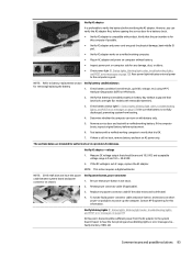
... system fan may have failed. Power Good (Troubleshooting) lights HP has added troubleshooting power lights to ZBook G3 Mobile Workstations (Studio, ZBook 15, and ZBook 17) to each computer model, see the WLAN module removal... section in the computer. Troubleshooting LEDs diagram ● Example: System board is required. CMOS Recovery CMOS Recovery Occurred 502 This message indicates that the primary battery has very low capacity. Battery Check Primary Battery Replace...
... system fan may have failed. Power Good (Troubleshooting) lights HP has added troubleshooting power lights to ZBook G3 Mobile Workstations (Studio, ZBook 15, and ZBook 17) to each computer model, see the WLAN module removal... section in the computer. Troubleshooting LEDs diagram ● Example: System board is required. CMOS Recovery CMOS Recovery Occurred 502 This message indicates that the primary battery has very low capacity. Battery Check Primary Battery Replace...

Maintenance and Service Guide
Page 91
...system time and hardware settings in addition to removing the AC adapter and battery. NOTE: Clearing the CMOS should only be removed to turn the computer over and look for the battery removal/replacement. 9. Reseat cables and connections NOTE: Before disassembling the computer to ...the computer. 5. General troubleshooting steps 77 Clear CMOS CMOS refers to Manuals > White papers > HP PC BIOS F10 Setup Guide. 10. See the RTC battery replacement section for a battery compartment door (service door). Sometimes it may be necessary to reset the system BIOS to abnormal movement...
...system time and hardware settings in addition to removing the AC adapter and battery. NOTE: Clearing the CMOS should only be removed to turn the computer over and look for the battery removal/replacement. 9. Reseat cables and connections NOTE: Before disassembling the computer to ...the computer. 5. General troubleshooting steps 77 Clear CMOS CMOS refers to Manuals > White papers > HP PC BIOS F10 Setup Guide. 10. See the RTC battery replacement section for a battery compartment door (service door). Sometimes it may be necessary to reset the system BIOS to abnormal movement...
Maintenance and Service Guide
Page 97
...; Inspect power port on pads/pins to power up the computer. Test battery with battery only. 5. Verify AC adapter It is preferable to verify the battery before replacement. 6. Check battery condition (overall result, cycle life, voltage, etc.) using HP PC Hardware Diagnostics (UEFI) or HPSA tools. 2. Determine whether the computer can short power-on computer side...
...; Inspect power port on pads/pins to power up the computer. Test battery with battery only. 5. Verify AC adapter It is preferable to verify the battery before replacement. 6. Check battery condition (overall result, cycle life, voltage, etc.) using HP PC Hardware Diagnostics (UEFI) or HPSA tools. 2. Determine whether the computer can short power-on computer side...

Maintenance and Service Guide
Page 102
...concern and report issues to HP. Further inspection on -board components. Hard reset on display screen when pressing F10. 4. Press power button and close the computer lid to force video output to isolate issue. If issue follows AC adapter or battery, replace it. 3. Remove all ...external video. POST No video (with external monitor via VGA port (or DisplayPort, HDMI, etc). If the issue persists, replace boards, AC adapter, and battery for multiple displays. ● Hard drive light blinking and hard drive noise Troubleshooting steps Quick check 1. Recently added hardware ...
...concern and report issues to HP. Further inspection on -board components. Hard reset on display screen when pressing F10. 4. Press power button and close the computer lid to force video output to isolate issue. If issue follows AC adapter or battery, replace it. 3. Remove all ...external video. POST No video (with external monitor via VGA port (or DisplayPort, HDMI, etc). If the issue persists, replace boards, AC adapter, and battery for multiple displays. ● Hard drive light blinking and hard drive noise Troubleshooting steps Quick check 1. Recently added hardware ...


