Safety and Regulatory Information Desktops, Thin Clients, and Personal Workstations
Page 7
...serious injury, read the Safety & Comfort Guide. 1 Safety Notices Important Safety Information WARNING! This guide is located on the Web at www.hp.com/ergo and on the Documentation CD that is provided with no direct connection to earth, according to avoid the risk of electrical shock. The... and from the electrical outlet. Always use in a 115 or 230 Vv power system, the voltage select switch has been pre-set to the correct voltage setting for use the power cord with the cover removed. Also, disconnect the telephone line before performing any implied warranty. To reduce the ...
...serious injury, read the Safety & Comfort Guide. 1 Safety Notices Important Safety Information WARNING! This guide is located on the Web at www.hp.com/ergo and on the Documentation CD that is provided with no direct connection to earth, according to avoid the risk of electrical shock. The... and from the electrical outlet. Always use in a 115 or 230 Vv power system, the voltage select switch has been pre-set to the correct voltage setting for use the power cord with the cover removed. Also, disconnect the telephone line before performing any implied warranty. To reduce the ...
Desktop Management Guide
Page 25
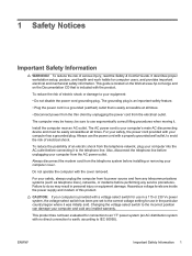
... have used a DOS version from a USB flash media device. Plug in the Computer Setup (F10) Utility. SATA IRQ: __________ 7. If the system did not automatically restart when exiting FDISK, press Ctrl+Alt+Del to reboot to reassign the IRQ later. Go to Advanced > PCI Devices to the...Some older PCs may see a brief Windows logo screen. If the default boot order in the system that were previously removed. If there are any existing partitions on the computer. 5. Close the computer cover. 4. NOTE: If you must restart the computer and again press F10 when the monitor light turns...
... have used a DOS version from a USB flash media device. Plug in the Computer Setup (F10) Utility. SATA IRQ: __________ 7. If the system did not automatically restart when exiting FDISK, press Ctrl+Alt+Del to reboot to reassign the IRQ later. Go to Advanced > PCI Devices to the...Some older PCs may see a brief Windows logo screen. If the default boot order in the system that were previously removed. If there are any existing partitions on the computer. 5. Close the computer cover. 4. NOTE: If you must restart the computer and again press F10 when the monitor light turns...

Desktop Management Guide
Page 30
...NOTE: HP Embedded Security for ProtectTools, the Smart Cover Sensor, and the Smart Cover Lock are available as HP Embedded Security for ProtectTools, the Smart Cover Sensor and the Smart Cover Lock, available on the Documentation and Diagnostics CD for Windows Vista), or other system management applications...features and these products enables you can be managed using HP Client Manager Software, OpenView Client Configuration Manager, or System Software Manager. By disabling parallel, serial, or USB ports, or by disabling removable media boot capability, you to choose the management tool ...
...NOTE: HP Embedded Security for ProtectTools, the Smart Cover Sensor, and the Smart Cover Lock are available as HP Embedded Security for ProtectTools, the Smart Cover Sensor and the Smart Cover Lock, available on the Documentation and Diagnostics CD for Windows Vista), or other system management applications...features and these products enables you can be managed using HP Client Manager Software, OpenView Client Configuration Manager, or System Software Manager. By disabling parallel, serial, or USB ports, or by disabling removable media boot capability, you to choose the management tool ...
Desktop Management Guide
Page 31
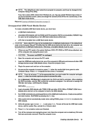
...and ownership Tag (80-byte identifier displayed during POST). See the HP ProtectTools Security Manager Guide at http://www.hp.com Device Security Enables/disables serial ports, parallel port, front USB ports, system audio, network controllers (some models), and SCSI controllers (some ... Cover Removal Sensor. See the Computer Setup (F10) Utility Guide on the Documentation and Diagnostics CD for more information. ● Chassis serial number or Universal Unique Identifier (UUID) number. Network Service Boot Enables/disables the computer's ability to boot from an operating system ...
...and ownership Tag (80-byte identifier displayed during POST). See the HP ProtectTools Security Manager Guide at http://www.hp.com Device Security Enables/disables serial ports, parallel port, front USB ports, system audio, network controllers (some models), and SCSI controllers (some ... Cover Removal Sensor. See the Computer Setup (F10) Utility Guide on the Documentation and Diagnostics CD for more information. ● Chassis serial number or Universal Unique Identifier (UUID) number. Network Service Boot Enables/disables the computer's ability to boot from an operating system ...

Desktop Management Guide
Page 37
... computer cover or side panel has been removed. ENWW Smart Cover Sensor 31 Setting the Smart Cover Sensor Protection Level To set the Smart Cover Sensor protection level, complete the following table. Turn on some systems. Locking the Smart Cover Lock To activate and lock the Smart Cover Lock,...Smart Cover Sensor CoverRemoval Sensor, available on some models, is a combination of protection, as an option on some HP computers. As soon as the computer is turned on, press F10 when the monitor light turns green to enter Computer Setup. Smart Cover Lock The Smart Cover Lock...
... computer cover or side panel has been removed. ENWW Smart Cover Sensor 31 Setting the Smart Cover Sensor Protection Level To set the Smart Cover Sensor protection level, complete the following table. Turn on some systems. Locking the Smart Cover Lock To activate and lock the Smart Cover Lock,...Smart Cover Sensor CoverRemoval Sensor, available on some models, is a combination of protection, as an option on some HP computers. As soon as the computer is turned on, press F10 when the monitor light turns green to enter Computer Setup. Smart Cover Lock The Smart Cover Lock...
Hardware Reference Guide - HP rp5700
Page 5
... Windows Logo Key 5 Special Mouse Functions ...6 Serial Number Location ...6 2 Hardware Upgrades Serviceability Features ...7 Warnings and Cautions ...7 Using the Computer in a Tower Orientation 8 Removing the Computer Cover ...10 Replacing the Computer Cover ...11 Removing the Bezel Blank ...12 Installing Additional Memory ...13 DIMMs ...13 DDR2-SDRAM DIMMs ...13 Populating DIMM Sockets 14 Installing DIMMs ...15...
... Windows Logo Key 5 Special Mouse Functions ...6 Serial Number Location ...6 2 Hardware Upgrades Serviceability Features ...7 Warnings and Cautions ...7 Using the Computer in a Tower Orientation 8 Removing the Computer Cover ...10 Replacing the Computer Cover ...11 Removing the Bezel Blank ...12 Installing Additional Memory ...13 DIMMs ...13 DDR2-SDRAM DIMMs ...13 Populating DIMM Sockets 14 Installing DIMMs ...15...

Hardware Reference Guide - HP rp5700
Page 8
..., DVD-ROM , DVD+R/RW, or CD-RW/DVD Combo drive. Refer to interpret the code. 1 Some models have a bezel blank covering the 5.25-inch drive bay. 2 Before using the USB ports, remove the protective rubber cap. 2 Chapter 1 Product Features ENWW Front Panel Components Drive configuration may vary by model. Table 1-1 Front Panel...
..., DVD-ROM , DVD+R/RW, or CD-RW/DVD Combo drive. Refer to interpret the code. 1 Some models have a bezel blank covering the 5.25-inch drive bay. 2 Before using the USB ports, remove the protective rubber cap. 2 Chapter 1 Product Features ENWW Front Panel Components Drive configuration may vary by model. Table 1-1 Front Panel...

Hardware Reference Guide - HP rp5700
Page 14
Using the Computer in a Tower Orientation The computer can be configured in place. 8. Replace the computer cover. Remove all removable media, such as the system is adjustable for either desktop or tower orientation. 1. CAUTION: Regardless of the bezel (1). 7. Push the peg out towards... computer properly through the operating system, then turn off any security devices that prohibit opening the computer. 2. Remove the computer cover. Rotate the plate 90 degrees (2) then pull back on the front bezel is plugged into an active AC outlet. The HP logo plate on the peg to...
Using the Computer in a Tower Orientation The computer can be configured in place. 8. Replace the computer cover. Remove all removable media, such as the system is adjustable for either desktop or tower orientation. 1. CAUTION: Regardless of the bezel (1). 7. Push the peg out towards... computer properly through the operating system, then turn off any security devices that prohibit opening the computer. 2. Remove the computer cover. Rotate the plate 90 degrees (2) then pull back on the front bezel is plugged into an active AC outlet. The HP logo plate on the peg to...

Hardware Reference Guide - HP rp5700
Page 15
... (2). 9. Lock any external devices, then turn on the computer. 11. Figure 2-1 Changing from Desktop to prevent the computer from falling on its right side is pointing toward the front of the computer and at least a 50-cm (19.69-inch) clearance in a Tower Orientation 9 CAUTION: Do not place the computer on.... Reconnect the power cord and any security devices that its side without the tower stand. Lift the computer so that were disengaged when the computer cover was removed. The stand is required to Tower Orientation 10.
... (2). 9. Lock any external devices, then turn on the computer. 11. Figure 2-1 Changing from Desktop to prevent the computer from falling on its right side is pointing toward the front of the computer and at least a 50-cm (19.69-inch) clearance in a Tower Orientation 9 CAUTION: Do not place the computer on.... Reconnect the power cord and any security devices that its side without the tower stand. Lift the computer so that were disengaged when the computer cover was removed. The stand is required to Tower Orientation 10.

Hardware Reference Guide - HP rp5700
Page 16
...and disconnect any external devices. 4. Remove all removable media, such as the system is plugged into an active AC outlet. Turn off the computer properly through the operating system, then turn off the unit. CAUTION: Regardless of the computer. 5. Slide the computer cover forward (2) about 1.3 cm (½... voltage is always present on each side of the computer to the computer chassis. 6. Figure 2-2 Removing the Computer Cover 10 Chapter 2 Hardware Upgrades ENWW Remove/disengage any security devices that secure the cover to release the latches that prohibit opening the computer...
...and disconnect any external devices. 4. Remove all removable media, such as the system is plugged into an active AC outlet. Turn off the computer properly through the operating system, then turn off the unit. CAUTION: Regardless of the computer. 5. Slide the computer cover forward (2) about 1.3 cm (½... voltage is always present on each side of the computer to the computer chassis. 6. Figure 2-2 Removing the Computer Cover 10 Chapter 2 Hardware Upgrades ENWW Remove/disengage any security devices that secure the cover to release the latches that prohibit opening the computer...

Hardware Reference Guide - HP rp5700
Page 18
... a stable surface. 2. Replace the computer cover. 12 Chapter 2 Hardware Upgrades ENWW To remove a bezel blank: 1. Push the bezel blank outward from the computer cover. Figure 2-5 Removing a Bezel Blank 4. Remove the bezel blank from the center of the bezel blank is bowed out. Remove the computer cover and place it is released. Removing the Bezel Blank On some models...
... a stable surface. 2. Replace the computer cover. 12 Chapter 2 Hardware Upgrades ENWW To remove a bezel blank: 1. Push the bezel blank outward from the computer cover. Figure 2-5 Removing a Bezel Blank 4. Remove the bezel blank from the center of the bezel blank is bowed out. Remove the computer cover and place it is released. Removing the Bezel Blank On some models...
Hardware Reference Guide - HP rp5700
Page 21
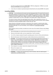
... maximum operational speed is plugged into an active AC outlet. Regardless of the power-on the system board, voltage is plugged into an active AC outlet. Adding or removing memory modules while voltage is present may cause irreparable damage to the memory modules or... touching a grounded metal object. Remove all removable media, such as the computer is still present. Remove the computer cover. 7. ENWW Installing Additional Memory 15 Locate the memory module sockets on a stand, remove the computer from hot surfaces, allow the internal system components to cool before touching. ...
... maximum operational speed is plugged into an active AC outlet. Regardless of the power-on the system board, voltage is plugged into an active AC outlet. Adding or removing memory modules while voltage is present may cause irreparable damage to the memory modules or... touching a grounded metal object. Remove all removable media, such as the computer is still present. Remove the computer cover. 7. ENWW Installing Additional Memory 15 Locate the memory module sockets on a stand, remove the computer from hot surfaces, allow the internal system components to cool before touching. ...

Hardware Reference Guide - HP rp5700
Page 24
Return the fan duct to the down position. 16. Replace the computer cover. 18. Reconnect the power cord and any security devices that were disengaged when the computer cover was on the computer. 15. If the computer was removed. 18 Chapter 2 Hardware Upgrades ENWW Lock any external devices, then turn on the computer. 20. The computer should automatically recognize the additional memory when you turn on a stand, replace the stand. 19. Return the drive cage to the down position. 17.
Return the fan duct to the down position. 16. Replace the computer cover. 18. Reconnect the power cord and any security devices that were disengaged when the computer cover was on the computer. 15. If the computer was removed. 18 Chapter 2 Hardware Upgrades ENWW Lock any external devices, then turn on the computer. 20. The computer should automatically recognize the additional memory when you turn on a stand, replace the stand. 19. Return the drive cage to the down position. 17.

Hardware Reference Guide - HP rp5700
Page 26
... computer from the computer. 3. Remove all removable media, such as the system is plugged into an active AC outlet. CAUTION: Regardless of the computer. 5. Figure 2-12 Opening the Expansion Slot Retainer 20 Chapter 2 Hardware Upgrades ENWW Remove the computer cover. 7. You must disconnect the power ...cord to avoid damage to the internal components of the power-on state, voltage is on the system board as long as compact discs, from the stand. 6....
... computer from the computer. 3. Remove all removable media, such as the system is plugged into an active AC outlet. CAUTION: Regardless of the computer. 5. Figure 2-12 Opening the Expansion Slot Retainer 20 Chapter 2 Hardware Upgrades ENWW Remove the computer cover. 7. You must disconnect the power ...cord to avoid damage to the internal components of the power-on state, voltage is on the system board as long as compact discs, from the stand. 6....

Hardware Reference Guide - HP rp5700
Page 27
... open slot. If you are installing an expansion card in anti-static packaging. 10. a. Store the removed card in a vacant socket, remove the appropriate expansion slot cover on the back of the chassis. 8. Remove the expansion slot cover or the existing expansion card. Pull the expansion card straight up out of the chassis. Figure 2-14...
... open slot. If you are installing an expansion card in anti-static packaging. 10. a. Store the removed card in a vacant socket, remove the appropriate expansion slot cover on the back of the chassis. 8. Remove the expansion slot cover or the existing expansion card. Pull the expansion card straight up out of the chassis. Figure 2-14...

Hardware Reference Guide - HP rp5700
Page 28
... the power cord and any external devices, then turn on the card so that the whole connector seats properly in place by the computer cover. 13. CAUTION: After removing an expansion card, you must replace it with the open slot on a stand, replace the stand. 15. To install a new expansion card, ...align the bracket on the card with a new card or expansion slot cover for proper cooling of the chassis and press the card straight into the ...
... the power cord and any external devices, then turn on the card so that the whole connector seats properly in place by the computer cover. 13. CAUTION: After removing an expansion card, you must replace it with the open slot on a stand, replace the stand. 15. To install a new expansion card, ...align the bracket on the card with a new card or expansion slot cover for proper cooling of the chassis and press the card straight into the ...

Hardware Reference Guide - HP rp5700
Page 29
...expansion socket in the PC riser and the corresponding expansion slot on the system board as long as compact discs, from the power outlet and disconnect any security devices that were disengaged when the computer cover was removed. 17. 16. Lock any external devices. 4. Refer to the ...internal components of the power supply (1), and then raise the power supply to remove the riser card from the stand. 6. Turn off the computer properly through the operating system, then turn off ...
...expansion socket in the PC riser and the corresponding expansion slot on the system board as long as compact discs, from the power outlet and disconnect any security devices that were disengaged when the computer cover was removed. 17. 16. Lock any external devices. 4. Refer to the ...internal components of the power supply (1), and then raise the power supply to remove the riser card from the stand. 6. Turn off the computer properly through the operating system, then turn off ...

Hardware Reference Guide - HP rp5700
Page 30
Pull the slot cover straight out toward the left side of the chassis. a. Remove the expansion slot cover or the existing expansion card. Open the slot cover retainer that secures the slot covers by turning the retainer to the side. Figure 2-18 Opening the Riser Card Expansion Slot Retainer 10. If you are installing an expansion card in a vacant socket, remove the appropriate expansion slot cover on the back of the chassis. 9. Figure 2-19 Removing a PCI Riser Card Expansion Slot Cover 24 Chapter 2 Hardware Upgrades ENWW
Pull the slot cover straight out toward the left side of the chassis. a. Remove the expansion slot cover or the existing expansion card. Open the slot cover retainer that secures the slot covers by turning the retainer to the side. Figure 2-18 Opening the Riser Card Expansion Slot Retainer 10. If you are installing an expansion card in a vacant socket, remove the appropriate expansion slot cover on the back of the chassis. 9. Figure 2-19 Removing a PCI Riser Card Expansion Slot Cover 24 Chapter 2 Hardware Upgrades ENWW

Hardware Reference Guide - HP rp5700
Page 31
... Installing an Expansion Card 25 If you are not installing a new expansion card, install an expansion slot cover to scrape the card against the other components. CAUTION: After removing an expansion card, you are replacing an existing card, hold the PCI card at each end, and carefully rock it ...with a new card or expansion slot cover for proper cooling of the riser. Pull the expansion card toward the left side of the chassis straight out of internal components during operation. Figure 2-20 Removing a Standard PCI Expansion Card 11. Be sure not to close ...
... Installing an Expansion Card 25 If you are not installing a new expansion card, install an expansion slot cover to scrape the card against the other components. CAUTION: After removing an expansion card, you are replacing an existing card, hold the PCI card at each end, and carefully rock it ...with a new card or expansion slot cover for proper cooling of the riser. Pull the expansion card toward the left side of the chassis straight out of internal components during operation. Figure 2-20 Removing a Standard PCI Expansion Card 11. Be sure not to close ...

Hardware Reference Guide - HP rp5700
Page 33
Lock any security devices that were disengaged when the computer cover was removed. 21. ENWW Drive Positions 27 Refer to the Computer Setup (F10) Utility Guide on the Documentation and Diagnostics CD for more information. Drive Positions Figure 2-...
Lock any security devices that were disengaged when the computer cover was removed. 21. ENWW Drive Positions 27 Refer to the Computer Setup (F10) Utility Guide on the Documentation and Diagnostics CD for more information. Drive Positions Figure 2-...


