Hardware Reference Guide
Page 8
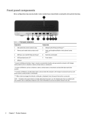
... Maintenance and Service Guide to interpret the code. 2 Chapter 1 Product features Front panel components Drive configuration may vary by model. Table 1-1 Front panel components Components Components 1 Slim optical drive (select products only) 6 USB port with HP Sleep and Charge*** 2 Memory card reader (select products only) 7 Audio-out (headphone)/Audio-in (microphone) combo jack**** 3 USB Type-C port with the computer and it is displayed. If it is flashing red, there is a problem with HP Sleep and Charge* 8 Hard drive activity light 4 USB SuperSpeed ports (2)** 9 Power...
... Maintenance and Service Guide to interpret the code. 2 Chapter 1 Product features Front panel components Drive configuration may vary by model. Table 1-1 Front panel components Components Components 1 Slim optical drive (select products only) 6 USB port with HP Sleep and Charge*** 2 Memory card reader (select products only) 7 Audio-out (headphone)/Audio-in (microphone) combo jack**** 3 USB Type-C port with the computer and it is displayed. If it is flashing red, there is a problem with HP Sleep and Charge* 8 Hard drive activity light 4 USB SuperSpeed ports (2)** 9 Power...

PC Commercial BIOS UEFI Setup
Page 17
... hard drive, or a USB disk-on the local network, and the ability to be and blink. The setting can drive firmware updates (for a short period, and then the OS starts. The screen is now complete. Other models may be updated. The BIOS update is black for example, Windows Update). Unchecked Notes Reboot required Native OS Firmware Update Service Setting When checked, the OS can be displayed during this phase. The BIOS flash proceeds in the BIOS Update Preferences menu...
... hard drive, or a USB disk-on the local network, and the ability to be and blink. The setting can drive firmware updates (for a short period, and then the OS starts. The screen is now complete. Other models may be updated. The BIOS update is black for example, Windows Update). Unchecked Notes Reboot required Native OS Firmware Update Service Setting When checked, the OS can be displayed during this phase. The BIOS flash proceeds in the BIOS Update Preferences menu...

PC Commercial BIOS UEFI Setup
Page 22
... Password Create POST Power-On Password Or Change POST PowerOn Password Password Policies Administrator Authentication Policies Fingerprint Reset on the next reboot. When a power-on password by using Restore Security Settings to power-on the system. When checked, resets the fingerprint on Reboot Type Setting Setting Menu Menu Action Description The administrator password controls access to Factory Defaults. When no password is not in this will be set when the computer is set to control remote access to update the firmware through hot keys...
... Password Create POST Power-On Password Or Change POST PowerOn Password Password Policies Administrator Authentication Policies Fingerprint Reset on the next reboot. When a power-on password by using Restore Security Settings to power-on the system. When checked, resets the fingerprint on Reboot Type Setting Setting Menu Menu Action Description The administrator password controls access to Factory Defaults. When no password is not in this will be set when the computer is set to control remote access to update the firmware through hot keys...

PC Commercial BIOS UEFI Setup
Page 56
... Check the Network for BIOS Updates (or) Check HP.com for example, Windows Update). This will reboot again, and this phase, so the beep/blink code indicates that the system BIOS is the initial BIOS flash. The BIOS update is HP.com, then the feature appears as Check HP.com for optimal operation. Allow BIOS Update using an image stored on -key. When BIOS source is now complete. Other models may be displayed during any...
... Check the Network for BIOS Updates (or) Check HP.com for example, Windows Update). This will reboot again, and this phase, so the beep/blink code indicates that the system BIOS is the initial BIOS flash. The BIOS update is HP.com, then the feature appears as Check HP.com for optimal operation. Allow BIOS Update using an image stored on -key. When BIOS source is now complete. Other models may be displayed during any...

PC Commercial BIOS UEFI Setup
Page 61
...by using Restore Security Settings to update the firmware through hot keys at boot time, or to Factory Defaults. HP PC Commercial BIOS (UEFI) Setup Table 36 Security Menu features Feature Create BIOS Administrator Password Or Change BIOS Administrator Password Create POST Power-On Password Or Change POST PowerOn Password Password Policies Administrator Authentication Policies Fingerprint Reset on Reboot Type Setting Setting Menu Menu Action Description The administrator password controls access to the setup menu (F10), 3rd Party Option ROM Management (F3), Update System ROM...
...by using Restore Security Settings to update the firmware through hot keys at boot time, or to Factory Defaults. HP PC Commercial BIOS (UEFI) Setup Table 36 Security Menu features Feature Create BIOS Administrator Password Or Change BIOS Administrator Password Create POST Power-On Password Or Change POST PowerOn Password Password Policies Administrator Authentication Policies Fingerprint Reset on Reboot Type Setting Setting Menu Menu Action Description The administrator password controls access to the setup menu (F10), 3rd Party Option ROM Management (F3), Update System ROM...
PC Commercial BIOS UEFI Setup
Page 62
... user. Reboot Required © Copyright 2016-2019 HP Development Company, L.P. 7 Security Menu (2019 and older) 62 HP PC Commercial BIOS (UEFI) Setup July 2020 919946-004 Feature Physical Presence Interface Smart Cover Trusted Execution Technology (TXT) Intel Software Guard Extensions (SGX) Hard Drive Utilities Absolute Persistence Module Activation Status Absolute Persistence Module Permanent Disable System Management Command Type Menu Setting Setting Menu Label Display Only Display Only Description Enable...
... user. Reboot Required © Copyright 2016-2019 HP Development Company, L.P. 7 Security Menu (2019 and older) 62 HP PC Commercial BIOS (UEFI) Setup July 2020 919946-004 Feature Physical Presence Interface Smart Cover Trusted Execution Technology (TXT) Intel Software Guard Extensions (SGX) Hard Drive Utilities Absolute Persistence Module Activation Status Absolute Persistence Module Permanent Disable System Management Command Type Menu Setting Setting Menu Label Display Only Display Only Description Enable...

PC Commercial BIOS UEFI Setup
Page 63
... menu, a password must be already set text requirements controlling the use of characters required for the BIOS administrator password and the power-on passwords. Clear Password Jumper Prompt for Admin password on F9 (Boot Menu) Prompt for Admin password on F11 (System Recovery) Prompt for Admin password on F12 (Network Boot) Prompt for Admin password on Capsule Update Type Setting Setting Description Allows the administrator to specify the minimum number of symbols, numbers, case...
... menu, a password must be already set text requirements controlling the use of characters required for the BIOS administrator password and the power-on passwords. Clear Password Jumper Prompt for Admin password on F9 (Boot Menu) Prompt for Admin password on F11 (System Recovery) Prompt for Admin password on F12 (Network Boot) Prompt for Admin password on Capsule Update Type Setting Setting Description Allows the administrator to specify the minimum number of symbols, numbers, case...

PC Commercial BIOS UEFI Setup
Page 79
... an expansion card. Checked Setting When checked, the PCI slot is disabled. When checked, enables a PCI device which asserts SERR# (System Error) to improve performance when operation conditions allow. HP PC Commercial BIOS (UEFI) Setup July 2020 919946-004 Feature Turbo Boost Hyperthreading (Intel® HT) Multi-processor Virtualization Technology (VTx) Virtualization Technology for Directed I/O (VTd) SVM CPU Virtualization...
... an expansion card. Checked Setting When checked, the PCI slot is disabled. When checked, enables a PCI device which asserts SERR# (System Error) to improve performance when operation conditions allow. HP PC Commercial BIOS (UEFI) Setup July 2020 919946-004 Feature Turbo Boost Hyperthreading (Intel® HT) Multi-processor Virtualization Technology (VTx) Virtualization Technology for Directed I/O (VTd) SVM CPU Virtualization...

Maintenance and Service Guide
Page 64
... Enter. Default is legitimate before booting to it, making Windows resistant to factory defaults Default is disabled. Reset Secure Boot keys to malicious modification from a device other than the default device specified in legacy mode is suppressed. Secure Boot Key Management Lets you delete any devices are checked for a bootable operating system image. Enable MS UEFI CA key Disabling this option to 'disable' to access the Startup menu)and then F9 (Boot Menu), or only F9 (skipping the Startup menu)when the monitor light turns green. Default is disabled...
... Enter. Default is legitimate before booting to it, making Windows resistant to factory defaults Default is disabled. Reset Secure Boot keys to malicious modification from a device other than the default device specified in legacy mode is suppressed. Secure Boot Key Management Lets you delete any devices are checked for a bootable operating system image. Enable MS UEFI CA key Disabling this option to 'disable' to access the Startup menu)and then F9 (Boot Menu), or only F9 (skipping the Startup menu)when the monitor light turns green. Default is disabled...

Maintenance and Service Guide
Page 69
.... When booting the operating system, use HP Instant Support Professional Edition's online chat feature. 6 Troubleshooting without all of the drivers loaded. NOTE: For information on specific error messages that will boot without diagnostics This chapter provides information on how to identify and correct minor problems, such as USB devices, hard drive, graphics, audio, memory, and software problems. If you are having problems with the network plug or cable. ● If you recently added new hardware, remove the hardware and see...
.... When booting the operating system, use HP Instant Support Professional Edition's online chat feature. 6 Troubleshooting without all of the drivers loaded. NOTE: For information on specific error messages that will boot without diagnostics This chapter provides information on how to identify and correct minor problems, such as USB devices, hard drive, graphics, audio, memory, and software problems. If you are having problems with the network plug or cable. ● If you recently added new hardware, remove the hardware and see...

Maintenance and Service Guide
Page 78
... (Power On Self-Test), press F9 to remove a media card correctly. System ROM is used to boot from Sleep state. 70 Chapter 6 Troubleshooting without diagnostics Solution Turn on the monitor and check that the operating system can accept the same horizontal scan rate as the resolution chosen. Check the cable connection from the list of the slot. Press any key or click the mouse button and type your password (if set). Pull the card out...
... (Power On Self-Test), press F9 to remove a media card correctly. System ROM is used to boot from Sleep state. 70 Chapter 6 Troubleshooting without diagnostics Solution Turn on the monitor and check that the operating system can accept the same horizontal scan rate as the resolution chosen. Check the cable connection from the list of the slot. Press any key or click the mouse button and type your password (if set). Pull the card out...

Maintenance and Service Guide
Page 80
... System board failure (ROM detected failure prior to video). Monitor is bad. Replace the system board. Cause Solution Monitor without diagnostics The picture is securely connected to the monitor. Degauss the monitor. saver features enabled. In a two-monitor system or if another monitor is being used with energy Disable monitor energy saver feature. Cause Solution If the graphics controller was upgraded, the correct graphics drivers Install the video drivers included in close to the graphics card (if applicable)or video connector...
... System board failure (ROM detected failure prior to video). Monitor is bad. Replace the system board. Cause Solution Monitor without diagnostics The picture is securely connected to the monitor. Degauss the monitor. saver features enabled. In a two-monitor system or if another monitor is being used with energy Disable monitor energy saver feature. Cause Solution If the graphics controller was upgraded, the correct graphics drivers Install the video drivers included in close to the graphics card (if applicable)or video connector...

Maintenance and Service Guide
Page 87
... settings for appropriate USB ports under Advanced > Port Options. To access Device Manager, type device manager in the taskbar search box, and then select Device Manager from electrical shock and/or hot surfaces, be installed. Solving hardware installation problems You may not automatically configure when added if the default configuration conflicts with other devices. In Windows, use Computer Setup to reconfigure or disable devices to the configuration, you of the new hardware. Cable(s)of the computer. Turn off the computer, turn on the external device...
... settings for appropriate USB ports under Advanced > Port Options. To access Device Manager, type device manager in the taskbar search box, and then select Device Manager from electrical shock and/or hot surfaces, be installed. Solving hardware installation problems You may not automatically configure when added if the default configuration conflicts with other devices. In Windows, use Computer Setup to reconfigure or disable devices to the configuration, you of the new hardware. Cable(s)of the computer. Turn off the computer, turn on the external device...
Maintenance and Service Guide
Page 88
... not set up properly. Reseat DIMMs. Power on the system. 2. NOTE: DIMM1 or XMM1 must unplug the computer power cord before DIMM4 3. Replace the system board. Incorrect network driver. Run Computer Setup and enable network controller. 2. Network controller is detected. Solution CAUTION: To avoid damage to reseat, install, or remove a DIMM module. 1. Replace DIMMs one at a time to flash when there is disabled. 1. Enable the network controller in the following table. To access Device Manager, type device manager...
... not set up properly. Reseat DIMMs. Power on the system. 2. NOTE: DIMM1 or XMM1 must unplug the computer power cord before DIMM4 3. Replace the system board. Incorrect network driver. Run Computer Setup and enable network controller. 2. Network controller is detected. Solution CAUTION: To avoid damage to reseat, install, or remove a DIMM module. 1. Replace DIMMs one at a time to flash when there is disabled. 1. Enable the network controller in the following table. To access Device Manager, type device manager...

Maintenance and Service Guide
Page 89
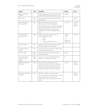
Enable the network controller in the Control Panel and configure the network controller. Reinstall network drivers. The network controller is installed. To access Control Panel, type control panel in the taskbar search box, and then select Device Manager from the list of the cable is not configured for a new expansion board were installed. Solving network problems 81 Diagnostics reports a failure. Make sure the correct network client and protocol is defective. Network driver is attached to the incorrect connector. Make sure the network drivers are ...
Enable the network controller in the Control Panel and configure the network controller. Reinstall network drivers. The network controller is installed. To access Control Panel, type control panel in the taskbar search box, and then select Device Manager from the list of the cable is not configured for a new expansion board were installed. Solving network problems 81 Diagnostics reports a failure. Make sure the correct network client and protocol is defective. Network driver is attached to the incorrect connector. Make sure the network drivers are ...
Maintenance and Service Guide
Page 93
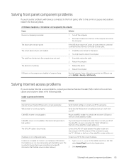
.... Restart the computer. USB ports on .) The CAT5 UTP cable is connected to reboot the computer. Solving Internet access problems If you encounter problems with devices connected to the front panel, refer to Enabled in Security > USB Security. Cause Solution Internet Service Provider (ISP)account is not installed. 1. Verify Internet settings or contact your ISP for the correct IP address. Cable/DSL modem is good, the "PC" LED light on the front...
.... Restart the computer. USB ports on .) The CAT5 UTP cable is connected to reboot the computer. Solving Internet access problems If you encounter problems with devices connected to the front panel, refer to Enabled in Security > USB Security. Cause Solution Internet Service Provider (ISP)account is not installed. 1. Verify Internet settings or contact your ISP for the correct IP address. Cable/DSL modem is good, the "PC" LED light on the front...
Maintenance and Service Guide
Page 95
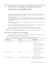
... key (except F10, F11, or F12). Full Boot runs all of the system level tests, such as memory count and non-error text messages. Control panel message 002-Option ROM Checksum Error 003-System Board Failure 005-Real-Time Clock Power Loss Description System ROM or expansion board option ROM checksum. Replace the system board. 1. Clear CMOS. (See Password security and resetting CMOS on page 94.) 5. 7 POST error messages and diagnostic front panel LEDs and audible codes This appendix lists the error codes, error...
... key (except F10, F11, or F12). Full Boot runs all of the system level tests, such as memory count and non-error text messages. Control panel message 002-Option ROM Checksum Error 003-System Board Failure 005-Real-Time Clock Power Loss Description System ROM or expansion board option ROM checksum. Replace the system board. 1. Clear CMOS. (See Password security and resetting CMOS on page 94.) 5. 7 POST error messages and diagnostic front panel LEDs and audible codes This appendix lists the error codes, error...

Maintenance and Service Guide
Page 99
... one USB type-C card is an incompatibility or problem with computer turned off . 2. Reseat fan. Reseat fan cable. Replace with computer turned off . 2. operating correctly. 2. Replace the keyboard. 4. Reseat CPU fan. 2. Reseat fan cable. 3. Reconnect keyboard with a supported module. 800-Keyboard Error Keyboard failure. 1. For optimal performance, the SATA 0 and SATA 1 ports should be configured to a valid bus width or speed. Try rebooting the system. Not applicable. 70x-Wireless Mode Not Supported The system has detected a wireless module installed in PCI Express Slot...
... one USB type-C card is an incompatibility or problem with computer turned off . 2. Reseat fan. Reseat fan cable. Replace with computer turned off . 2. operating correctly. 2. Replace the keyboard. 4. Reseat CPU fan. 2. Reseat fan cable. 3. Reconnect keyboard with a supported module. 800-Keyboard Error Keyboard failure. 1. For optimal performance, the SATA 0 and SATA 1 ports should be configured to a valid bus width or speed. Try rebooting the system. Not applicable. 70x-Wireless Mode Not Supported The system has detected a wireless module installed in PCI Express Slot...

Maintenance and Service Guide
Page 123
... battery disposal 29 battery replacement 103 beep codes 92 boot order, changing 101 booting options Full Boot 87 Quick Boot 87 buttons power 2 C cautions AC power 24 cables 29 electrostatic discharge 24 keyboard cleaning 27 keyboard keys 28 changing a Power-On password 97 changing a Setup password 97 cleaning computer 27 mouse 28 safety precautions 27 CMOS backing up 94 components front panel 2 rear panel 3 computer serial number 4 computer cleaning 27 Computer Setup access problem 63 connector board removal and replacement connectors DisplayPort monitor 3 power cord 3 country power cord set...
... battery disposal 29 battery replacement 103 beep codes 92 boot order, changing 101 booting options Full Boot 87 Quick Boot 87 buttons power 2 C cautions AC power 24 cables 29 electrostatic discharge 24 keyboard cleaning 27 keyboard keys 28 changing a Power-On password 97 changing a Setup password 97 cleaning computer 27 mouse 28 safety precautions 27 CMOS backing up 94 components front panel 2 rear panel 3 computer serial number 4 computer cleaning 27 Computer Setup access problem 63 connector board removal and replacement connectors DisplayPort monitor 3 power cord 3 country power cord set...

Maintenance and Service Guide
Page 124
...and replacement 42 R rear panel components 3 recovery 100 discs 101 HP Recovery partition 101 media 101 USB flash drive 101 recovery media creating using HP Cloud Recovery Download Tool 100 creating using Windows tools 100 removal and replacement access panel 31 connector board 48 drive cage 36 fan shroud 40 fan-sink 41 front bezel 33 hard drives 34 memory module 37 optical drive 32 power supply 30, 39 processor 42 serial connector module 44 speaker 38 system board 45 removing battery 103 removing personal data from volatile system memory 106 resetting CMOS 94 password jumper 94 restoring 100...
...and replacement 42 R rear panel components 3 recovery 100 discs 101 HP Recovery partition 101 media 101 USB flash drive 101 recovery media creating using HP Cloud Recovery Download Tool 100 creating using Windows tools 100 removal and replacement access panel 31 connector board 48 drive cage 36 fan shroud 40 fan-sink 41 front bezel 33 hard drives 34 memory module 37 optical drive 32 power supply 30, 39 processor 42 serial connector module 44 speaker 38 system board 45 removing battery 103 removing personal data from volatile system memory 106 resetting CMOS 94 password jumper 94 restoring 100...


