Expansion Base - Maintenance and Service Guide
Page 4
... 5-2 5.2 Disassembly Sequence Chart 5-3 5.3 Preparing the HP Notebook Expansion Base for Disassembly 5-4 5.4 Base Plate 5-5 5.5 Upper Chassis 5-6 5.6 Power Supply 5-10 5.7 System Board 5-12 5.8 Front Tray Cover 5-14 5.9 Back Panel 5-16 5.10 Expansion Cable 5-17 5.11 Speaker Assembly 5-18 5.12 Front Case 5-20 6 Specifications A Connector Pin Assignments B Power Cord Set Requirements 3-Conductor Power Cord Set B-1 General Requirements B-1 Country-Specific...
... 5-2 5.2 Disassembly Sequence Chart 5-3 5.3 Preparing the HP Notebook Expansion Base for Disassembly 5-4 5.4 Base Plate 5-5 5.5 Upper Chassis 5-6 5.6 Power Supply 5-10 5.7 System Board 5-12 5.8 Front Tray Cover 5-14 5.9 Back Panel 5-16 5.10 Expansion Cable 5-17 5.11 Speaker Assembly 5-18 5.12 Front Case 5-20 6 Specifications A Connector Pin Assignments B Power Cord Set Requirements 3-Conductor Power Cord Set B-1 General Requirements B-1 Country-Specific...
Expansion Base - Maintenance and Service Guide
Page 16
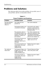
... the above solutions are unsuccessful, the power supply may be malfunctioning. Plug the Expansion Base into an AC power outlet, draining the notebook battery pack. The Expansion Base is not powered on the Expansion Base is unsuccessful, the power supply may be malfunctioning. If the above ... are unsuccessful, the expansion cable may be damaged. The expansion cable on . Replace the power supply. (Section 5.6) The notebook shuts down. Turn on . Turn off the notebook and unplug the expansion cable. Troubleshooting Problems and Solutions The following tables list possible problems, the...
... the above solutions are unsuccessful, the power supply may be malfunctioning. Plug the Expansion Base into an AC power outlet, draining the notebook battery pack. The Expansion Base is not powered on the Expansion Base is unsuccessful, the power supply may be malfunctioning. If the above ... are unsuccessful, the expansion cable may be damaged. The expansion cable on . Replace the power supply. (Section 5.6) The notebook shuts down. Turn on . Turn off the notebook and unplug the expansion cable. Troubleshooting Problems and Solutions The following tables list possible problems, the...
Expansion Base - Maintenance and Service Guide
Page 20
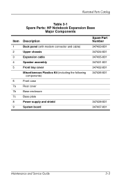
Illustrated Parts Catalog Table 3-1 Spare Parts: HP Notebook Expansion Base Major Components Item 1 2 3 4 5 6 7a 7b 7c 8 9 Description Back panel (with modem connector and cable) Upper chassis Expansion cable Speaker assembly Front tray cover Miscellaneous Plastics Kit (including the following components) Front case Rear cover Base enclosure Base plate Power supply and shield System board Spare Part Number 347433-001 347434-001 347435-001 347431-001 347432-001 347436-001 347438-001 347437-001 Maintenance and Service Guide 3-3
Illustrated Parts Catalog Table 3-1 Spare Parts: HP Notebook Expansion Base Major Components Item 1 2 3 4 5 6 7a 7b 7c 8 9 Description Back panel (with modem connector and cable) Upper chassis Expansion cable Speaker assembly Front tray cover Miscellaneous Plastics Kit (including the following components) Front case Rear cover Base enclosure Base plate Power supply and shield System board Spare Part Number 347433-001 347434-001 347435-001 347431-001 347432-001 347436-001 347438-001 347437-001 Maintenance and Service Guide 3-3

Expansion Base - Maintenance and Service Guide
Page 32
Section 5.3 5.4 5.5 5.6 5.7 5.8 5.9 5.10 5.11 5.12 Disassembly Sequence Chart Description # of Screws Removed Preparing the Expansion Base for disassembly Base plate 4 Upper chassis 2 Power supply 5 System board 5 Front tray cover 4 Back panel 4 Expansion cable 4 Speaker assembly 2 Front case 6 Maintenance and Service Guide 5-3 Removal and Replacement Procedures 5.2 Disassembly Sequence Chart Use the chart below to determine the section number to be referenced when removing Expansion Base components.
Section 5.3 5.4 5.5 5.6 5.7 5.8 5.9 5.10 5.11 5.12 Disassembly Sequence Chart Description # of Screws Removed Preparing the Expansion Base for disassembly Base plate 4 Upper chassis 2 Power supply 5 System board 5 Front tray cover 4 Back panel 4 Expansion cable 4 Speaker assembly 2 Front case 6 Maintenance and Service Guide 5-3 Removal and Replacement Procedures 5.2 Disassembly Sequence Chart Use the chart below to determine the section number to be referenced when removing Expansion Base components.

Expansion Base - Maintenance and Service Guide
Page 39
Prepare the Expansion Base for disassembly (Section 5.3). 2. Remove the base plate (Section 5.4). 3. Removing the power supply screws 5-10 Maintenance and Service Guide Removal and Replacement Procedures 5.6 Power Supply Spare Part Number Information Power supply 347438-001 1. While holding the power supply in place with the front facing you. 5. Remove the upper chassis (Section 5.5). 4. Turn the base enclosure upside down with one hand underneath, remove the five PM2.0×6.0 screws that secure the power supply to the base enclosure.
Prepare the Expansion Base for disassembly (Section 5.3). 2. Remove the base plate (Section 5.4). 3. Removing the power supply screws 5-10 Maintenance and Service Guide Removal and Replacement Procedures 5.6 Power Supply Spare Part Number Information Power supply 347438-001 1. While holding the power supply in place with the front facing you. 5. Remove the upper chassis (Section 5.5). 4. Turn the base enclosure upside down with one hand underneath, remove the five PM2.0×6.0 screws that secure the power supply to the base enclosure.

Expansion Base - Maintenance and Service Guide
Page 40
Maintenance and Service Guide 5-11 Removal and Replacement Procedures 6. While holding the power supply and shield, remove the power connector 3 from the system board. 8. Turn the base enclosure right-side up with the rear facing you. 7. On the base enclosure, disconnect the power supply cable 1 from the supports in the base enclosure. Lift the power supply and shield approximately one inch 2. 9. Removing the power supply Reverse the above procedure to install the power supply.
Maintenance and Service Guide 5-11 Removal and Replacement Procedures 6. While holding the power supply and shield, remove the power connector 3 from the system board. 8. Turn the base enclosure right-side up with the rear facing you. 7. On the base enclosure, disconnect the power supply cable 1 from the supports in the base enclosure. Lift the power supply and shield approximately one inch 2. 9. Removing the power supply Reverse the above procedure to install the power supply.

Expansion Base - Maintenance and Service Guide
Page 41
... three PM2.0×6.0 screws 1 that secure the system board to remove the two HM5.0x9.0 standoffs 2 on either side of the serial connector. Remove the power supply (Section 5.6). 5. Use a 5.0-mm hex socket to the base enclosure. 7. Remove the upper chassis (Section 5.5). 4. Removing the system board screws and standoffs 5-12 Maintenance and Service...
... three PM2.0×6.0 screws 1 that secure the system board to remove the two HM5.0x9.0 standoffs 2 on either side of the serial connector. Remove the power supply (Section 5.6). 5. Use a 5.0-mm hex socket to the base enclosure. 7. Remove the upper chassis (Section 5.5). 4. Removing the system board screws and standoffs 5-12 Maintenance and Service...

Expansion Base - Maintenance and Service Guide
Page 50
6 Specifications This chapter provides physical and performance specifications. Table 6-1 HP Notebook Expansion Base Dimensions Height Width Depth 22.8 cm 31.8 cm 29.8 cm Weight 3.5 kg Stand-alone power requirements Power supply 18.5 V at 8 amps 9 in 12.5 in 11.75 in 7.5 lb Temperature Operating (not writing optical) Operating (writing optical) Nonoperating 0°C ...) Operating Nonoperating 10% to 90% 5% to 140°F ✎ Applicable product safety standards specify thermal limits for plastic surfaces. The notebook operates well within this range of temperatures.
6 Specifications This chapter provides physical and performance specifications. Table 6-1 HP Notebook Expansion Base Dimensions Height Width Depth 22.8 cm 31.8 cm 29.8 cm Weight 3.5 kg Stand-alone power requirements Power supply 18.5 V at 8 amps 9 in 12.5 in 11.75 in 7.5 lb Temperature Operating (not writing optical) Operating (writing optical) Nonoperating 0°C ...) Operating Nonoperating 10% to 90% 5% to 140°F ✎ Applicable product safety standards specify thermal limits for plastic surfaces. The notebook operates well within this range of temperatures.

Expansion Base - Maintenance and Service Guide
Page 51
Specifications Power supply Rated input voltage Rated input current Rated frequency Table 6-2 Internal AC Adapter 160 W with PFC 100 to 240 VAC RMS 1.7 A RMS 47 to 63 Hz 6-2 Maintenance and Service Guide
Specifications Power supply Rated input voltage Rated input current Rated frequency Table 6-2 Internal AC Adapter 160 W with PFC 100 to 240 VAC RMS 1.7 A RMS 47 to 63 Hz 6-2 Maintenance and Service Guide

Expansion Base - Maintenance and Service Guide
Page 62
Screw Listing Table C-2 Phillips PM2.0×6.0 Screw mm Color Qty. Length Thread Bronze 10 6.0 mm 2.0 mm Where used: Five screws that secure the power supply to the base enclosure (documented in Section 5.6) Head Width 4.5 mm Phillips M2.0×6.0 screw locations Maintenance and Service Guide C-3
Screw Listing Table C-2 Phillips PM2.0×6.0 Screw mm Color Qty. Length Thread Bronze 10 6.0 mm 2.0 mm Where used: Five screws that secure the power supply to the base enclosure (documented in Section 5.6) Head Width 4.5 mm Phillips M2.0×6.0 screw locations Maintenance and Service Guide C-3
Expansion Base - Maintenance and Service Guide
Page 73
... Plastics Kit, spare part number 3-3 modem jack, pin assignments A-2 mouse, wireless 1-9 mute button 1-4 N network jack, pin assignments A-1 P packing precautions 4-3 plastic parts 4-2 power connector 1-7 power cord set requirements B-1 power cord, spare part numbers 3-6 power supply removal 5-10 spare part number 3-3 R rear components 1-5 rear cover removal 5-6 spare part number 3-3 receiver function 1-9 spare part number 3-5 removal preliminaries 4-1 replacement...
... Plastics Kit, spare part number 3-3 modem jack, pin assignments A-2 mouse, wireless 1-9 mute button 1-4 N network jack, pin assignments A-1 P packing precautions 4-3 plastic parts 4-2 power connector 1-7 power cord set requirements B-1 power cord, spare part numbers 3-6 power supply removal 5-10 spare part number 3-3 R rear components 1-5 rear cover removal 5-6 spare part number 3-3 receiver function 1-9 spare part number 3-5 removal preliminaries 4-1 replacement...

Software Guide
Page 3
... Resuming After a Short Interval 1-4 When Resuming After a Week or More 1-4 When External Power Supply Is Disrupted or Uncertain 1-4 When Using Infrared or Drive Media 1-5 Standby, Hibernation and Shutdown Procedures 1-5 Identifying Power Controls and Indicators 1-6 Using the Default Power Settings 1-7 Turning the Notebook or Display On or Off 1-7 Initiating or Resuming from Hibernation 1-8 Initiating or Resuming...
... Resuming After a Short Interval 1-4 When Resuming After a Week or More 1-4 When External Power Supply Is Disrupted or Uncertain 1-4 When Using Infrared or Drive Media 1-5 Standby, Hibernation and Shutdown Procedures 1-5 Identifying Power Controls and Indicators 1-6 Using the Default Power Settings 1-7 Turning the Notebook or Display On or Off 1-7 Initiating or Resuming from Hibernation 1-8 Initiating or Resuming...
Software Guide
Page 10
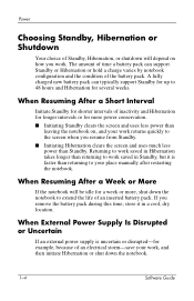
... example, because of an electrical storm-save your work, and then initiate Hibernation or shut down the notebook to work saved in a cool, dry location. When External Power Supply Is Disrupted or Uncertain If an external power supply is faster than returning to your work returns quickly to the screen when you work. Returning to...
... example, because of an electrical storm-save your work, and then initiate Hibernation or shut down the notebook to work saved in a cool, dry location. When External Power Supply Is Disrupted or Uncertain If an external power supply is faster than returning to your work returns quickly to the screen when you work. Returning to...

Software Guide
Page 68
... to do 4-15 battery pack causing CD or DVD write corruption 3-7 when to remove 1-3 battery power vs. AC power 4-8 BIOS (basic input output system) 4-1 boot order 4-14 C CDs Application Recovery 4-12 CD-R vs. Index A AC power devices that supply 1-1 using Hibernation with 1-8 using Standby with WinDVD 3-5 speed 3-7 customer support 4-25 D device security 2-10 display...
... to do 4-15 battery pack causing CD or DVD write corruption 3-7 when to remove 1-3 battery power vs. AC power 4-8 BIOS (basic input output system) 4-1 boot order 4-14 C CDs Application Recovery 4-12 CD-R vs. Index A AC power devices that supply 1-1 using Hibernation with 1-8 using Standby with WinDVD 3-5 speed 3-7 customer support 4-25 D device security 2-10 display...

Getting Started
Page 12
... the notebook on battery power or shut down the notebook and disconnect the power cord. Hardware and Software Setup Protecting the Notebook from Power Surges To protect the notebook from most computer or electronics retailers. Surge protectors are available from the power surges that might be caused by an unreliable power supply or an electrical storm: ■ Plug the notebook power cord...
... the notebook on battery power or shut down the notebook and disconnect the power cord. Hardware and Software Setup Protecting the Notebook from Power Surges To protect the notebook from most computer or electronics retailers. Surge protectors are available from the power surges that might be caused by an unreliable power supply or an electrical storm: ■ Plug the notebook power cord...


