
Expansion Base Reference Guide
Page 10
.... Reference Guide 2-1 Arrange them so that is easily accessible at all times. ■ Disconnect power from the equipment by unplugging the power cord from the electrical outlet, grasp the cord by the plug. 2 Connecting and Removing the Notebook Connecting to AC Power Å WARNING: To reduce the risk of personal injury, electric shock, fire, or damage...
.... Reference Guide 2-1 Arrange them so that is easily accessible at all times. ■ Disconnect power from the equipment by unplugging the power cord from the electrical outlet, grasp the cord by the plug. 2 Connecting and Removing the Notebook Connecting to AC Power Å WARNING: To reduce the risk of personal injury, electric shock, fire, or damage...

Expansion Base Reference Guide
Page 11
Connecting and Removing the Notebook For optimal performance, connect the Expansion Base to AC power (power cords and outlets vary by region and country) 2-2 Reference Guide Plug the power cable into the wall outlet. Connecting to AC power.
Connecting and Removing the Notebook For optimal performance, connect the Expansion Base to AC power (power cords and outlets vary by region and country) 2-2 Reference Guide Plug the power cable into the wall outlet. Connecting to AC power.
Expansion Base - Maintenance and Service Guide
Page 4
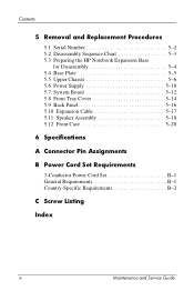
... 5-2 5.2 Disassembly Sequence Chart 5-3 5.3 Preparing the HP Notebook Expansion Base for Disassembly 5-4 5.4 Base Plate 5-5 5.5 Upper Chassis 5-6 5.6 Power Supply 5-10 5.7 System Board 5-12 5.8 Front Tray Cover 5-14 5.9 Back Panel 5-16 5.10 Expansion Cable 5-17 5.11 Speaker Assembly 5-18 5.12 Front Case 5-20 6 Specifications A Connector Pin Assignments B Power Cord Set Requirements 3-Conductor Power Cord Set B-1 General Requirements B-1 Country-Specific Requirements...
... 5-2 5.2 Disassembly Sequence Chart 5-3 5.3 Preparing the HP Notebook Expansion Base for Disassembly 5-4 5.4 Base Plate 5-5 5.5 Upper Chassis 5-6 5.6 Power Supply 5-10 5.7 System Board 5-12 5.8 Front Tray Cover 5-14 5.9 Back Panel 5-16 5.10 Expansion Cable 5-17 5.11 Speaker Assembly 5-18 5.12 Front Case 5-20 6 Specifications A Connector Pin Assignments B Power Cord Set Requirements 3-Conductor Power Cord Set B-1 General Requirements B-1 Country-Specific Requirements...
Expansion Base - Maintenance and Service Guide
Page 11
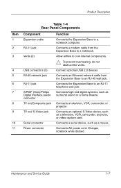
...RJ-11 jack S/PDIF (Sony/Philips Digital Interface) audio connector TV out/Composite jack TV out/ S-Video jack Serial connector Power connector Ä To prevent overheating, do not obstruct the vents. Connect optional USB 2.0 devices Connects an Ethernet network cable ... camcorder, or projector. Connects an optional S-Video device, such as a mouse. Maintenance and Service Guide 1-7 Charges notebook while docked. Allow airflow to a notebook. Connects AC power cord. Connects high-end digital systems, such as surround sound or a home theatre. Connects a modem cable from the ...
...RJ-11 jack S/PDIF (Sony/Philips Digital Interface) audio connector TV out/Composite jack TV out/ S-Video jack Serial connector Power connector Ä To prevent overheating, do not obstruct the vents. Connect optional USB 2.0 devices Connects an Ethernet network cable ... camcorder, or projector. Connects an optional S-Video device, such as a mouse. Maintenance and Service Guide 1-7 Charges notebook while docked. Allow airflow to a notebook. Connects AC power cord. Connects high-end digital systems, such as surround sound or a home theatre. Connects a modem cable from the ...
Expansion Base - Maintenance and Service Guide
Page 17
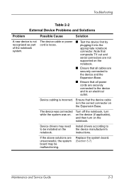
... all cables are securely connected to an electrical outlet. The device cable or power cord is in the correct connector on the notebook. Note that composite TV out and serial connectors are not supported on the notebook. ■ Ensure that all power cords are unsuccessful, the system board may need to the device manufacturer's instructions. Install...
... all cables are securely connected to an electrical outlet. The device cable or power cord is in the correct connector on the notebook. Note that composite TV out and serial connectors are not supported on the notebook. ■ Ensure that all power cords are unsuccessful, the system board may need to the device manufacturer's instructions. Install...

Expansion Base - Maintenance and Service Guide
Page 23
Illustrated Parts Catalog Table 3-2 Spare Parts: HP Notebook Expansion Base Miscellaneous Components (not illustrated) Item Description Power cord Australia Brazil Denmark Europe French Canada Israel India Italy Japan Korea China Switzerland United Kingdom United States Spare Part Number 345252-011 345252-201 345252-081 345252-021 345252-121 345252-BB1 345252-D61 345252-061 345252-291 345252-AD1 345252-AA1 345252-111 345252-031 345252-001 3-6 Maintenance and Service Guide
Illustrated Parts Catalog Table 3-2 Spare Parts: HP Notebook Expansion Base Miscellaneous Components (not illustrated) Item Description Power cord Australia Brazil Denmark Europe French Canada Israel India Italy Japan Korea China Switzerland United Kingdom United States Spare Part Number 345252-011 345252-201 345252-081 345252-021 345252-121 345252-BB1 345252-D61 345252-061 345252-291 345252-AD1 345252-AA1 345252-111 345252-031 345252-001 3-6 Maintenance and Service Guide
Expansion Base - Maintenance and Service Guide
Page 57
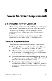
...the appliance inlet on the back of the notebook. B Power Cord Set Requirements 3-Conductor Power Cord Set The wide range input feature of the notebook permits it to operate from any line voltage from 100 to 120 or 220 to all countries: ■ The length of the power cord set must be at least 1.5 meters ... of an EN 60 320/IEC 320 Standard Sheet C13 connector for mating with the notebook meets the requirements for use in the country where the power cord set will be approved by each country's power system. ■ The appliance coupler must meet the requirements of the country where the...
...the appliance inlet on the back of the notebook. B Power Cord Set Requirements 3-Conductor Power Cord Set The wide range input feature of the notebook permits it to operate from any line voltage from 100 to 120 or 220 to all countries: ■ The length of the power cord set must be at least 1.5 meters ... of an EN 60 320/IEC 320 Standard Sheet C13 connector for mating with the notebook meets the requirements for use in the country where the power cord set will be approved by each country's power system. ■ The appliance coupler must meet the requirements of the country where the...
Expansion Base - Maintenance and Service Guide
Page 59
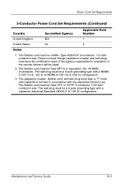
... for evaluation in accordance with a NEMA 5-15P (15 A, 125 V) or NEMA 6-15P (15 A, 250 V) configuration. 3. Power Cord Set Requirements 3-Conductor Power Cord Set Requirements (Continued) Country United Kingdom United States Notes Accredited Agency BSI UL Applicable Note Number 1 2 1. Power cord set fittings (appliance coupler and wall plug) must be a 2-pole grounding type with a Japanese Industrial Standard...
... for evaluation in accordance with a NEMA 5-15P (15 A, 125 V) or NEMA 6-15P (15 A, 250 V) configuration. 3. Power Cord Set Requirements 3-Conductor Power Cord Set Requirements (Continued) Country United Kingdom United States Notes Accredited Agency BSI UL Applicable Note Number 1 2 1. Power cord set fittings (appliance coupler and wall plug) must be a 2-pole grounding type with a Japanese Industrial Standard...
Expansion Base - Maintenance and Service Guide
Page 73
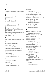
... 1-5 M Miscellaneous Plastics Kit, spare part number 3-3 modem jack, pin assignments A-2 mouse, wireless 1-9 mute button 1-4 N network jack, pin assignments A-1 P packing precautions 4-3 plastic parts 4-2 power connector 1-7 power cord set requirements B-1 power cord, spare part numbers 3-6 power supply removal 5-10 spare part number 3-3 R rear components 1-5 rear cover removal 5-6 spare part number 3-3 receiver function 1-9 spare part number 3-5 removal preliminaries 4-1 replacement...
... 1-5 M Miscellaneous Plastics Kit, spare part number 3-3 modem jack, pin assignments A-2 mouse, wireless 1-9 mute button 1-4 N network jack, pin assignments A-1 P packing precautions 4-3 plastic parts 4-2 power connector 1-7 power cord set requirements B-1 power cord, spare part numbers 3-6 power supply removal 5-10 spare part number 3-3 R rear components 1-5 rear cover removal 5-6 spare part number 3-3 receiver function 1-9 spare part number 3-5 removal preliminaries 4-1 replacement...
Compaq Notebook Series - Maintenance, Shipping and Travel Guide
Page 14
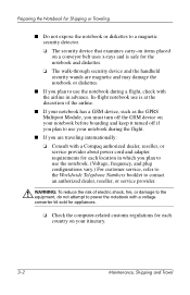
... shock, fire, or damage to the equipment, do not attempt to use the notebook during a flight, check with a Compaq authorized dealer, reseller, or service provider about power cord and adapter requirements for Shipping or Traveling ■ Do not expose the notebook or diskettes to a magnetic security detector. ❏ The security device that examines carry...
... shock, fire, or damage to the equipment, do not attempt to use the notebook during a flight, check with a Compaq authorized dealer, reseller, or service provider about power cord and adapter requirements for Shipping or Traveling ■ Do not expose the notebook or diskettes to a magnetic security detector. ❏ The security device that examines carry...
Hardware Guide
Page 3
Contents 1 Hardware Components Identifying Parts of the Notebook 1-1 Display 1-1 TouchPad 1-2 Top Components 1-3 Power Lights 1-3 Keyboard and Drive Lights 1-4 Power and Volume Controls 1-5 Wireless On/Off Button and ...Application Keys. . . . . 1-6 Function and Keypad Keys 1-7 Front Components 1-8 Rear Components 1-10 Left-Side Components 1-11 Right-Side Components 1-13 Bottom Components 1-15 Labels 1-16 Additional Standard Components 1-17 Documentation Library CD 1-17 Cords...
Contents 1 Hardware Components Identifying Parts of the Notebook 1-1 Display 1-1 TouchPad 1-2 Top Components 1-3 Power Lights 1-3 Keyboard and Drive Lights 1-4 Power and Volume Controls 1-5 Wireless On/Off Button and ...Application Keys. . . . . 1-6 Function and Keypad Keys 1-7 Front Components 1-8 Rear Components 1-10 Left-Side Components 1-11 Right-Side Components 1-13 Bottom Components 1-15 Labels 1-16 Additional Standard Components 1-17 Documentation Library CD 1-17 Cords...
Hardware Guide
Page 25
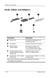
.... 5 Japan-specific outlet adapter Connects the AC adapter to a country-specific modem adapter. Hardware Components Cords, Cables and Adapters Component Description 1 Power cord* Connects the AC adapter to an AC electrical outlet. 2 AC adapter** Converts AC power to DC power. 3 Modem cables (select models)* 4 Country-specific modem adapter (included by region as required) Connects the...
.... 5 Japan-specific outlet adapter Connects the AC adapter to a country-specific modem adapter. Hardware Components Cords, Cables and Adapters Component Description 1 Power cord* Connects the AC adapter to an AC electrical outlet. 2 AC adapter** Converts AC power to DC power. 3 Modem cables (select models)* 4 Country-specific modem adapter (included by region as required) Connects the...
Hardware Guide
Page 72
If you are connecting a powered device, plug the device power cord into a grounded electrical outlet. 4. To disconnect a standard external device from the notebook, turn off . 2. Turn on the notebook. 3. To connect a standard external device to the new device. If you are connecting a powered device, be sure that the device is turned off the device (if it is...
If you are connecting a powered device, plug the device power cord into a grounded electrical outlet. 4. To disconnect a standard external device from the notebook, turn off . 2. Turn on the notebook. 3. To connect a standard external device to the new device. If you are connecting a powered device, be sure that the device is turned off the device (if it is...
Hardware Guide
Page 98
... the only user-accessible internal compartments on this CD. 1. Hardware Upgrades Removing or Inserting a Memory Module Å WARNING: To prevent exposure to the notebook, shut down the notebook, unplug the power cord, and remove all battery packs before installing a memory module. Ä CAUTION: To prevent electrostatic discharge from damaging electronic components: Before beginning this...
... the only user-accessible internal compartments on this CD. 1. Hardware Upgrades Removing or Inserting a Memory Module Å WARNING: To prevent exposure to the notebook, shut down the notebook, unplug the power cord, and remove all battery packs before installing a memory module. Ä CAUTION: To prevent electrostatic discharge from damaging electronic components: Before beginning this...

Hardware Guide
Page 103
... Hardware Guide Save your work , exit all external devices connected to the screen, save your work returns to the notebook. 3. Disconnect the power cord or other external power source. 4. If your work and shut down the notebook. Hardware Upgrades Replacing the Hard Drive Remove the hard drive only for replacement. Disconnect all applications, and then...
... Hardware Guide Save your work , exit all external devices connected to the screen, save your work returns to the notebook. 3. Disconnect the power cord or other external power source. 4. If your work and shut down the notebook. Hardware Upgrades Replacing the Hard Drive Remove the hard drive only for replacement. Disconnect all applications, and then...
Hardware Guide
Page 113
See external devices (optional) pointing devices setting preferences 2-2 TouchPad 2-1 power conserving 3-9 light 1-3 Power Options window 3-5 rated input 9-1 resolving low-battery conditions 3-6 switching between AC and battery 3-1 power button 1-5 power cord 1-18 power/Standby light 1-3, 1-8 Product Key 1-16 R RAM (Random Access Memory) 8-8 regulatory information Modem ... switching display to or from 2-5 P PAL, PAL-M television formats 5-6 parallel connector, identifying 1-10 PC Card component locations 1-11 configuring 8-2 functions 8-2 increasing RAM 8-8 inserting/removing 8-3 peripherals.
See external devices (optional) pointing devices setting preferences 2-2 TouchPad 2-1 power conserving 3-9 light 1-3 Power Options window 3-5 rated input 9-1 resolving low-battery conditions 3-6 switching between AC and battery 3-1 power button 1-5 power cord 1-18 power/Standby light 1-3, 1-8 Product Key 1-16 R RAM (Random Access Memory) 8-8 regulatory information Modem ... switching display to or from 2-5 P PAL, PAL-M television formats 5-6 parallel connector, identifying 1-10 PC Card component locations 1-11 configuring 8-2 functions 8-2 increasing RAM 8-8 inserting/removing 8-3 peripherals.
Getting Started
Page 7
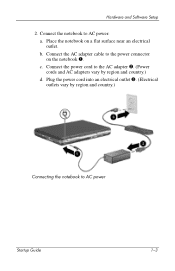
b. Connect the power cord to the AC adapter 2. (Power cords and AC adapters vary by region and country.) Connecting the notebook to AC power Startup Guide 1-3 Plug the power cord into an electrical outlet 3. (Electrical outlets vary by region and country.) d. Connect the AC adapter cable to AC power: a. Place the notebook on the notebook 1. c. Hardware and Software Setup 2. Connect the notebook to the power connector on a flat surface near an electrical outlet.
b. Connect the power cord to the AC adapter 2. (Power cords and AC adapters vary by region and country.) Connecting the notebook to AC power Startup Guide 1-3 Plug the power cord into an electrical outlet 3. (Electrical outlets vary by region and country.) d. Connect the AC adapter cable to AC power: a. Place the notebook on the notebook 1. c. Hardware and Software Setup 2. Connect the notebook to the power connector on a flat surface near an electrical outlet.

Getting Started
Page 12
... the telephone jack. ■ During an electrical storm, run the notebook on battery power or shut down the notebook and disconnect the power cord. Surge protectors are available from the power surges that might be caused by an unreliable power supply or an electrical storm: ■ Plug the notebook power cord into an optional, high-quality surge protector. ■ Provide...
... the telephone jack. ■ During an electrical storm, run the notebook on battery power or shut down the notebook and disconnect the power cord. Surge protectors are available from the power surges that might be caused by an unreliable power supply or an electrical storm: ■ Plug the notebook power cord into an optional, high-quality surge protector. ■ Provide...
Getting Started
Page 14
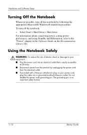
... by following the appropriate Microsoft® Windows® shutdown procedure: To turn off the notebook: » Select Start > Shut Down > Shut down. Hardware and Software Setup Turning Off the Notebook Whenever possible, turn off the notebook by unplugging the power cord from the electrical outlet. ■ If provided with a three-pin attachment plug on the...
... by following the appropriate Microsoft® Windows® shutdown procedure: To turn off the notebook: » Select Start > Shut Down > Shut down. Hardware and Software Setup Turning Off the Notebook Whenever possible, turn off the notebook by unplugging the power cord from the electrical outlet. ■ If provided with a three-pin attachment plug on the...
Getting Started
Page 38
Index P parallel connector, identifying 3-10 PC Card 3-12 power button 1-5 power connector 1-3 power cord 1-3 power features power button 3-5 power/Standby light 3-3 power, AC 1-3, 1-5, 1-10 power/Standby light 3-8 problems and solutions 2-1 protection against viruses 1-10 R regional...considerations 1-8 screen settings 1-7 security cable slot 3-11 See also connectors; infrared port 3-14 Service ID tag 2-4 shutting down the notebook 1-9 software Adobe Acrobat Reader 2-2 antivirus 1-10 installing 1-7 license 1-6 setup 1-6 Software Setup utility 1-7 space requirements 1-7 Software Guide 2-1...
Index P parallel connector, identifying 3-10 PC Card 3-12 power button 1-5 power connector 1-3 power cord 1-3 power features power button 3-5 power/Standby light 3-3 power, AC 1-3, 1-5, 1-10 power/Standby light 3-8 problems and solutions 2-1 protection against viruses 1-10 R regional...considerations 1-8 screen settings 1-7 security cable slot 3-11 See also connectors; infrared port 3-14 Service ID tag 2-4 shutting down the notebook 1-9 software Adobe Acrobat Reader 2-2 antivirus 1-10 installing 1-7 license 1-6 setup 1-6 Software Setup utility 1-7 space requirements 1-7 Software Guide 2-1...

