Presario CQ56 Battery Replacement - HP 200 Notebook PC
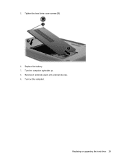
Presario CQ56 Battery Replacement
View Results Below
Free HP Presario CQ56-200 manuals!
Problems with HP Presario CQ56-200?
Ask a Question
Free HP Presario CQ56-200 manuals!
Problems with HP Presario CQ56-200?
Ask a Question
Related Manual Pages


Similar Questions

How To Get To The Cmos Battery
dv 3500. Have it apart. Cannot identify the cmos battery
dv 3500. Have it apart. Cannot identify the cmos battery
(Posted by tr5869 6 years ago)

