
Expansion Base Reference Guide
Page 28
... 3-9 Plug one of the Expansion Base. Plug one end of one end of the other RJ-11 cable into the RJ-11 jack on the notebook. Connecting a modem through the Expansion Base to the RJ-11 wall jack. Plug the other end of the Expansion Base 1. 2. Plug the other end of... of the cable into the RJ-11 jack on the lower rear panel of the modem cables into the RJ-11 wall jack 2. ✎ A country-specific modem adapter also may be required in addition to the RJ-11 cable connected to your Expansion Base. 1. This requires the RJ-11 modem cables...
... 3-9 Plug one of the Expansion Base. Plug one end of one end of the other RJ-11 cable into the RJ-11 jack on the notebook. Connecting a modem through the Expansion Base to the RJ-11 wall jack. Plug the other end of the Expansion Base 1. 2. Plug the other end of... of the cable into the RJ-11 jack on the lower rear panel of the modem cables into the RJ-11 wall jack 2. ✎ A country-specific modem adapter also may be required in addition to the RJ-11 cable connected to your Expansion Base. 1. This requires the RJ-11 modem cables...
Expansion Base - Maintenance and Service Guide
Page 4
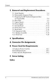
... Procedures 5.1 Serial Number 5-2 5.2 Disassembly Sequence Chart 5-3 5.3 Preparing the HP Notebook Expansion Base for Disassembly 5-4 5.4 Base Plate 5-5 5.5 Upper Chassis 5-6 5.6 Power Supply 5-10 5.7 System Board 5-12 5.8 Front Tray Cover 5-14 5.9 Back Panel 5-16 5.10 Expansion Cable 5-17 5.11 Speaker Assembly 5-18 5.12 Front Case 5-20 6 Specifications A Connector Pin Assignments B Power Cord Set Requirements 3-Conductor Power...
... Procedures 5.1 Serial Number 5-2 5.2 Disassembly Sequence Chart 5-3 5.3 Preparing the HP Notebook Expansion Base for Disassembly 5-4 5.4 Base Plate 5-5 5.5 Upper Chassis 5-6 5.6 Power Supply 5-10 5.7 System Board 5-12 5.8 Front Tray Cover 5-14 5.9 Back Panel 5-16 5.10 Expansion Cable 5-17 5.11 Speaker Assembly 5-18 5.12 Front Case 5-20 6 Specifications A Connector Pin Assignments B Power Cord Set Requirements 3-Conductor Power...

Expansion Base - Maintenance and Service Guide
Page 50
...of temperatures. Relative humidity (noncondensing) Operating Nonoperating 10% to 90% 5% to 140°F ✎ Applicable product safety standards specify thermal limits for plastic surfaces. Table 6-1 HP Notebook Expansion Base Dimensions Height Width Depth 22.8 cm 31.8 cm 29.8 cm Weight 3.5 kg Stand-alone power requirements Power supply 18.5 V at 8 amps 9 in 12... 32°F to 95°F 41°F to 95°F -4°F to 95%, 38.7°C (101.6°F) maximum wet bulb temperature Maintenance and Service Guide 6-1 6 Specifications This chapter provides physical and performance...
...of temperatures. Relative humidity (noncondensing) Operating Nonoperating 10% to 90% 5% to 140°F ✎ Applicable product safety standards specify thermal limits for plastic surfaces. Table 6-1 HP Notebook Expansion Base Dimensions Height Width Depth 22.8 cm 31.8 cm 29.8 cm Weight 3.5 kg Stand-alone power requirements Power supply 18.5 V at 8 amps 9 in 12... 32°F to 95°F 41°F to 95°F -4°F to 95%, 38.7°C (101.6°F) maximum wet bulb temperature Maintenance and Service Guide 6-1 6 Specifications This chapter provides physical and performance...

Expansion Base - Maintenance and Service Guide
Page 51
Specifications Power supply Rated input voltage Rated input current Rated frequency Table 6-2 Internal AC Adapter 160 W with PFC 100 to 240 VAC RMS 1.7 A RMS 47 to 63 Hz 6-2 Maintenance and Service Guide
Specifications Power supply Rated input voltage Rated input current Rated frequency Table 6-2 Internal AC Adapter 160 W with PFC 100 to 240 VAC RMS 1.7 A RMS 47 to 63 Hz 6-2 Maintenance and Service Guide

Expansion Base - Maintenance and Service Guide
Page 60
Maintenance and Service Guide C-1 C Screw Listing This appendix provides specification and reference information for the screws used in the Miscellaneous Screw Kit, spare part number 347439-001. All screws listed in this appendix are available in the HP Notebook Expansion Base.
Maintenance and Service Guide C-1 C Screw Listing This appendix provides specification and reference information for the screws used in the Miscellaneous Screw Kit, spare part number 347439-001. All screws listed in this appendix are available in the HP Notebook Expansion Base.

Expansion Base - Maintenance and Service Guide
Page 72
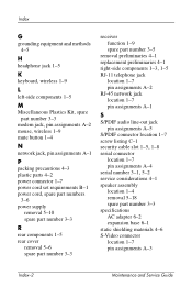
Index A AC adapter specifications 6-2 audio line-out pin assignments A-3 B back panel removal 5-16 spare part number 3-3 base enclosure, spare part number 3-3 base plate removal...out jack A-5 serial connector A-4 S-Video connector A-3 USB connectors A-2 connectors, service considerations 4-2 D design overview 1-10 disassembly sequence chart 5-3 E electrostatic discharge 4-2, 4-6 expansion base specifications 6-1 expansion cable 1-4, 1-7 disconnecting 5-4 removal 5-17 spare part number 3-3 F features 1-2 front case removal 5-20 spare part number 3-3 front components 1-3 front tray cover removal ...
Index A AC adapter specifications 6-2 audio line-out pin assignments A-3 B back panel removal 5-16 spare part number 3-3 base enclosure, spare part number 3-3 base plate removal...out jack A-5 serial connector A-4 S-Video connector A-3 USB connectors A-2 connectors, service considerations 4-2 D design overview 1-10 disassembly sequence chart 5-3 E electrostatic discharge 4-2, 4-6 expansion base specifications 6-1 expansion cable 1-4, 1-7 disconnecting 5-4 removal 5-17 spare part number 3-3 F features 1-2 front case removal 5-20 spare part number 3-3 front components 1-3 front tray cover removal ...
Expansion Base - Maintenance and Service Guide
Page 73
... A-5 S/PDIF connector location 1-7 screw listing C-1 security cable slot 1-5, 1-8 serial connector location 1-7 pin assignments A-4 serial number 3-1, 5-2 service considerations 4-1 speaker assembly location 1-4 removal 5-18 spare part number 3-3 specifications AC adapter 6-2 expansion base 6-1 static shielding materials 4-6 S-Video connector location 1-7 pin assignments A-3 Index-2 Maintenance and Service Guide
... A-5 S/PDIF connector location 1-7 screw listing C-1 security cable slot 1-5, 1-8 serial connector location 1-7 pin assignments A-4 serial number 3-1, 5-2 service considerations 4-1 speaker assembly location 1-4 removal 5-18 spare part number 3-3 specifications AC adapter 6-2 expansion base 6-1 static shielding materials 4-6 S-Video connector location 1-7 pin assignments A-3 Index-2 Maintenance and Service Guide
Compaq and HP Notebook PC Series - Using a Wireless LAN Adapter
Page 2
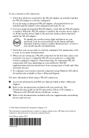
... point is subject to enable the WLAN adapter. To identify the wireless device light and button on your notebook, look on . If the wireless device light is correctly configured. HP shall not be liable for the button and light identified with the wireless symbol illustrated here, or refer...are using an integrated WLAN adapter, verify that your access point documentation. 4. Verify that the WLAN adapter is on your model-specific documentation. 3. For more information about using Windows XP, follow the instructions available at Start > Help and Support. ■ Refer to your...
... point is subject to enable the WLAN adapter. To identify the wireless device light and button on your notebook, look on . If the wireless device light is correctly configured. HP shall not be liable for the button and light identified with the wireless symbol illustrated here, or refer...are using an integrated WLAN adapter, verify that your access point documentation. 4. Verify that the WLAN adapter is on your model-specific documentation. 3. For more information about using Windows XP, follow the instructions available at Start > Help and Support. ■ Refer to your...
Hardware Guide
Page 1
It also includes power and environmental specifications, which might be helpful when traveling with the notebook. Hardware Guide HP Notebook Series Document Part Number: 355386-001 November 2003 This guide explains how to identify and use notebook hardware features, including connectors for external devices.
It also includes power and environmental specifications, which might be helpful when traveling with the notebook. Hardware Guide HP Notebook Series Document Part Number: 355386-001 November 2003 This guide explains how to identify and use notebook hardware features, including connectors for external devices.

Hardware Guide
Page 7
Contents Using Digital Media Cards (Select Models 8-6 Inserting an Optional Digital Media Card 8-7 Removing an Optional Digital Media Card 8-9 Disabling an Optional Digital Media Card 8-10 Increasing Memory 8-11 Displaying Memory Information 8-11 Removing or Inserting a Memory Module 8-12 Replacing the Hard Drive 8-21 Finding More Upgrade Information 8-28 9 Specifications Operating Environment 9-1 Rated Input Power 9-2 Index Hardware Guide vii
Contents Using Digital Media Cards (Select Models 8-6 Inserting an Optional Digital Media Card 8-7 Removing an Optional Digital Media Card 8-9 Disabling an Optional Digital Media Card 8-10 Increasing Memory 8-11 Displaying Memory Information 8-11 Removing or Inserting a Memory Module 8-12 Replacing the Hard Drive 8-21 Finding More Upgrade Information 8-28 9 Specifications Operating Environment 9-1 Rated Input Power 9-2 Index Hardware Guide vii

Hardware Guide
Page 39
...list the countries in order to use . Hardware Components Labels The labels affixed to the bottom of the notebook and to the inside of the battery compartment are specific to various types of optional wireless devices. You might need this number to update or troubleshoot problems with ...the notebook. ■ The Service Tag label affixed to the bottom of the notebook contains the product name, product number (P/N), and ...
...list the countries in order to use . Hardware Components Labels The labels affixed to the bottom of the notebook and to the inside of the battery compartment are specific to various types of optional wireless devices. You might need this number to update or troubleshoot problems with ...the notebook. ■ The Service Tag label affixed to the bottom of the notebook contains the product name, product number (P/N), and ...

Hardware Guide
Page 41
Adapts the modem cable to a non-RJ-11 telephone jack. 5 Japan-specific outlet adapter Connects the AC adapter to a 2-prong (Japan only) electrical outlet. *Power cords and modem cables vary in appearance by region. **AC adapters vary ...by region as required) Connects the modem to an RJ-11 telephone jack or to DC power. 3 Modem cables (select models)* 4 Country-specific modem adapter (included by region. 1-34 Hardware Guide Hardware Components Cords, Cables and Adapters Component Description 1 Power cord* Connects the AC adapter to an AC...
Adapts the modem cable to a non-RJ-11 telephone jack. 5 Japan-specific outlet adapter Connects the AC adapter to a 2-prong (Japan only) electrical outlet. *Power cords and modem cables vary in appearance by region. **AC adapters vary ...by region as required) Connects the modem to an RJ-11 telephone jack or to DC power. 3 Modem cables (select models)* 4 Country-specific modem adapter (included by region. 1-34 Hardware Guide Hardware Components Cords, Cables and Adapters Component Description 1 Power cord* Connects the AC adapter to an AC...

Hardware Guide
Page 73
... object, and (2) Avoid touching the connectors on the Documentation Library CD. ■ Excessive force can damage electronic components. To prevent electrostatic damage to the notebook or a drive, follow these 2 precautions: (1) Before handling a drive, discharge yourself from shock, vibration, extreme temperatures, and high humidity. For more ... is still in use. ■ Electrostatic discharge can damage drive connectors. The following cautions apply to all drives. Cautions that concern specific procedures are fragile notebook components that must be handled with the procedures.
... object, and (2) Avoid touching the connectors on the Documentation Library CD. ■ Excessive force can damage electronic components. To prevent electrostatic damage to the notebook or a drive, follow these 2 precautions: (1) Before handling a drive, discharge yourself from shock, vibration, extreme temperatures, and high humidity. For more ... is still in use. ■ Electrostatic discharge can damage drive connectors. The following cautions apply to all drives. Cautions that concern specific procedures are fragile notebook components that must be handled with the procedures.

Hardware Guide
Page 104
...television formats are modes by which television video signals are set at the factory for most notebooks, but the region setting can be using the same color television format. Region-specific formats are sent and received. When the device is off the device before disconnecting the device...5-9 Select the Advanced button. 3. Other South American and Central American countries might use one of the following methods: ■ Start or restart the notebook. ■ Access the ATI Displays tab: 1. To turn off , an image is common in Brazil. Select the ATI Displays tab and select...
...television formats are modes by which television video signals are set at the factory for most notebooks, but the region setting can be using the same color television format. Region-specific formats are sent and received. When the device is off the device before disconnecting the device...5-9 Select the Advanced button. 3. Other South American and Central American countries might use one of the following methods: ■ Start or restart the notebook. ■ Access the ATI Displays tab: 1. To turn off , an image is common in Brazil. Select the ATI Displays tab and select...

Hardware Guide
Page 118
...the modem cable into the telephone jack 3. Plug the modem cable into the RJ-11 jack on this CD. Connecting a modem cable using your notebook internationally, refer to an analog telephone line that does not have an RJ-11 telephone jack: 1. To use the modem and the RJ-11 cable... outside the country in which you purchased the notebook, you must obtain a country-specific modem adapter. Plug the country-specific modem adapter into the country-specific modem adapter 2. 3. To connect the modem to the Modem and Networking guide on the...
...the modem cable into the telephone jack 3. Plug the modem cable into the RJ-11 jack on this CD. Connecting a modem cable using your notebook internationally, refer to an analog telephone line that does not have an RJ-11 telephone jack: 1. To use the modem and the RJ-11 cable... outside the country in which you purchased the notebook, you must obtain a country-specific modem adapter. Plug the country-specific modem adapter into the country-specific modem adapter 2. 3. To connect the modem to the Modem and Networking guide on the...
Hardware Guide
Page 120
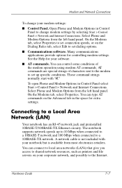
On the Modems tab, select Properties. The notebook supports network speeds up specific conditions. Many communications applications provide options for extra settings... conditions of characters sent to the modem to a Local Area Network (LAN) Your notebook has an RJ-45 network jack and preinstalled 10BASE-T/100BASE-TX Ethernet circuity. Hardware Guide 7-7 You can ...type AT commands on your notebook but is not included with "AT." Modem and Network Connections To change modem settings by ...
On the Modems tab, select Properties. The notebook supports network speeds up specific conditions. Many communications applications provide options for extra settings... conditions of characters sent to the modem to a Local Area Network (LAN) Your notebook has an RJ-45 network jack and preinstalled 10BASE-T/100BASE-TX Ethernet circuity. Hardware Guide 7-7 You can ...type AT commands on your notebook but is not included with "AT." Modem and Network Connections To change modem settings by ...
Hardware Guide
Page 130
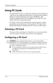
... is a credit card-sized accessory designed to conform to the standard specifications of PC card (Type I or Type II) to use other software, such as card services, socket services, or enablers, that might not be used to add modem, ... device drivers: ■ Do not install other PC Cards. PC Smart Card Reader and biometric identification PC Cards can be able to use in your notebook varies by model. PC Cards can add security. The notebook supports both 32-bit (CardBus) and 16-bit PC Cards, which will vary by a PC Card manufacturer, you might also be supplied...
... is a credit card-sized accessory designed to conform to the standard specifications of PC card (Type I or Type II) to use other software, such as card services, socket services, or enablers, that might not be used to add modem, ... device drivers: ■ Do not install other PC Cards. PC Smart Card Reader and biometric identification PC Cards can be able to use in your notebook varies by model. PC Cards can add security. The notebook supports both 32-bit (CardBus) and 16-bit PC Cards, which will vary by a PC Card manufacturer, you might also be supplied...

Hardware Guide
Page 157
9 Specifications Operating Environment Factor Metric Temperature Operating 0° to 35°C (non writing optical) 5° to 35°C (writing optical) Nonoperating -20° to 60°C Relative humidity (noncondensing) Operating 10% to 90% Nonoperating 5% to 95% Altitude (unpressurized) Operating -15 to 3,048 m Nonoperating -15 to 12,192 m U.S. 32° to 95°F 41° to 95°F -4° to 140°F 10% to 90% 5% to 95% -50 to 10,000 ft -50 to 40,000 ft Hardware Guide 9-1
9 Specifications Operating Environment Factor Metric Temperature Operating 0° to 35°C (non writing optical) 5° to 35°C (writing optical) Nonoperating -20° to 60°C Relative humidity (noncondensing) Operating 10% to 90% Nonoperating 5% to 95% Altitude (unpressurized) Operating -15 to 3,048 m Nonoperating -15 to 12,192 m U.S. 32° to 95°F 41° to 95°F -4° to 140°F 10% to 90% 5% to 95% -50 to 10,000 ft -50 to 40,000 ft Hardware Guide 9-1

Hardware Guide
Page 158
Specifications Rated Input Power Input Power Rating Operating voltage 100-240 VAC RMS Operating frequency range 50 to 60 Hz AC When powered by a DC source 18.5 Vdc 6.5 A ✎ This product is designed for IT power systems in Norway with phase-to-phase voltage not exceeding 240 Vrms. 9-2 Hardware Guide
Specifications Rated Input Power Input Power Rating Operating voltage 100-240 VAC RMS Operating frequency range 50 to 60 Hz AC When powered by a DC source 18.5 Vdc 6.5 A ✎ This product is designed for IT power systems in Norway with phase-to-phase voltage not exceeding 240 Vrms. 9-2 Hardware Guide

Hardware Guide
Page 159
Index A AC adapter disconnecting 3-1 identifying 1-34 adapter, modem 7-5 airport security devices 4-3 altitude specifications 9-1 AT commands 7-7 audio devices, connecting 5-4 audio-out jack connecting devices 5-6 location 5-4 AutoPlay/Autorun 4-5 B battery ...condition 3-6 recycling 3-12 storing 3-11 switching power sources 3-1 battery release latch 1-30, 1-31 blackout periods, modem 7-6 Bluetooth wireless 7-15 bottom components 1-30, 1-31 buttons PC Card eject 1-22, 1-24, 8-5 power 1-9, 1-10 Quick Launch 1-11 scroll 2-2, 2-3 TouchPad 2-2, 2-3 volume 1-9, 1-10, 1-17, 1-28, 5-1, 5-2 wireless ...
Index A AC adapter disconnecting 3-1 identifying 1-34 adapter, modem 7-5 airport security devices 4-3 altitude specifications 9-1 AT commands 7-7 audio devices, connecting 5-4 audio-out jack connecting devices 5-6 location 5-4 AutoPlay/Autorun 4-5 B battery ...condition 3-6 recycling 3-12 storing 3-11 switching power sources 3-1 battery release latch 1-30, 1-31 blackout periods, modem 7-6 Bluetooth wireless 7-15 bottom components 1-30, 1-31 buttons PC Card eject 1-22, 1-24, 8-5 power 1-9, 1-10 Quick Launch 1-11 scroll 2-2, 2-3 TouchPad 2-2, 2-3 volume 1-9, 1-10, 1-17, 1-28, 5-1, 5-2 wireless ...


