Pavilion zd8000 Battery Replacement - HP Notebook PC
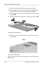
Pavilion zd8000 Battery Replacement
View Results Below
Free HP Pavilion zd8000 manuals!
Problems with HP Pavilion zd8000?
Ask a Question
Free HP Pavilion zd8000 manuals!
Problems with HP Pavilion zd8000?
Ask a Question
Related Manual Pages


Related Videos

HP 's Worst Laptop Ever - Pavilion ZD8000 -
Duration: 1:44
Total Views: 101,167
Duration: 1:44
Total Views: 101,167
Similar Questions

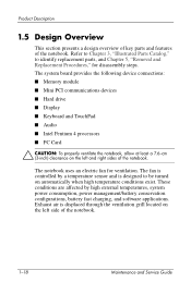
How To Open Zd8000 Laptop To Replace Video Card. Hve Removed All Screws But Can
How to open zd8000 laptop to replace video card. Removed all screws but could not take apart unit. P...
How to open zd8000 laptop to replace video card. Removed all screws but could not take apart unit. P...
(Posted by romeolampa 5 years ago)

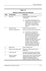
How To Get To The Cmos Battery
dv 3500. Have it apart. Cannot identify the cmos battery
dv 3500. Have it apart. Cannot identify the cmos battery
(Posted by tr5869 6 years ago)

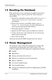
Cmos Battery Location
I messed up the CMOS password and need to reset it, to get into the laptop
I messed up the CMOS password and need to reset it, to get into the laptop
(Posted by buddylemaster 11 years ago)
Can I Replace Mother Board To Amd
Can I replace mother board to amd
Can I replace mother board to amd
(Posted by metzgrafx 11 years ago)
