
Drives
Page 4
... a medium. ■ Avoid exposing a drive to temperature or humidity extremes. ■ Avoid exposing a drive to vibration. ■ When the battery pack is sensitive to liquids. The airport security devices that the battery pack is writing to another. ■ Before handling a drive, discharge static electricity by touching the unpainted metal surface of magnetism...
... a medium. ■ Avoid exposing a drive to temperature or humidity extremes. ■ Avoid exposing a drive to vibration. ■ When the battery pack is sensitive to liquids. The airport security devices that the battery pack is writing to another. ■ Before handling a drive, discharge static electricity by touching the unpainted metal surface of magnetism...

Drives
Page 7
Turn the computer upside down the computer and close the display. 3. Loosen the 3 hard drive cover screws 1. 5. Lift the hard drive cover away from the computer 2. ✎ Select models have a secondary hard drive bay for a secondary hard drive. Drives 5 Save your information. 2. The primary hard drive bay is marked with a "1" and the secondary hard drive bay is marked with the battery toward you. 4. To remove the primary hard drive: 1. Shut down , with a "2."
Turn the computer upside down the computer and close the display. 3. Loosen the 3 hard drive cover screws 1. 5. Lift the hard drive cover away from the computer 2. ✎ Select models have a secondary hard drive bay for a secondary hard drive. Drives 5 Save your information. 2. The primary hard drive bay is marked with a "1" and the secondary hard drive bay is marked with the battery toward you. 4. To remove the primary hard drive: 1. Shut down , with a "2."

Drives
Page 14
Removing an optical disc (with power) If the computer is not fully accessbile, tilt the disc carefully as you remove it. 4. Press the release button 1 on external or battery power: 1. Drives 12 Hold the disc by gently pressing down on the computer. 2. Close the media tray and place the disc in a protective case. Remove the disc 3 from the tray by the edges, and avoid touching the flat surfaces. ✎ If the tray is running on the drive bezel to release the media tray, and then pull out the tray 2. 3. Turn on the spindle while lifting the outer edges of the disc.
Removing an optical disc (with power) If the computer is not fully accessbile, tilt the disc carefully as you remove it. 4. Press the release button 1 on external or battery power: 1. Drives 12 Hold the disc by gently pressing down on the computer. 2. Close the media tray and place the disc in a protective case. Remove the disc 3 from the tray by the edges, and avoid touching the flat surfaces. ✎ If the tray is running on the drive bezel to release the media tray, and then pull out the tray 2. 3. Turn on the spindle while lifting the outer edges of the disc.

Drives
Page 15
... disc by gently pressing down on the spindle while lifting the outer edges of the disc. Removing an optical disc (without power) If external or battery power are not available: 1. Insert the end of the drive. 2. Close the media tray and place the disc in the front bezel of a paper clip...
... disc by gently pressing down on the spindle while lifting the outer edges of the disc. Removing an optical disc (without power) If external or battery power are not available: 1. Insert the end of the drive. 2. Close the media tray and place the disc in the front bezel of a paper clip...

Memory Modules
Page 3
... primary memory module slot. Å WARNING: To reduce the risk of electric shock and damage to the equipment, unplug the power cord and remove all battery packs before installing a memory module. Ä CAUTION: Electrostatic discharge (ESD) can be upgraded by adding a memory module to the Electrostatic Discharge guide. For more information...
... primary memory module slot. Å WARNING: To reduce the risk of electric shock and damage to the equipment, unplug the power cord and remove all battery packs before installing a memory module. Ä CAUTION: Electrostatic discharge (ESD) can be upgraded by adding a memory module to the Electrostatic Discharge guide. For more information...

Memory Modules
Page 4
To add or replace a memory module: 1. Loosen the memory module compartment cover screws 1. 7. Shut down the computer through the operating system.) 2. Disconnect the power cord. 4. Memory Modules 2 Remove the battery pack from the computer. Lift the memory module compartment cover 2 away from the computer. 6. Disconnect all external devices connected to the computer. 3. Then shut down the computer. (If you are not sure whether the computer is off or in hibernation, turn the computer on by pressing the power button. Turn the computer upside down. 5.
To add or replace a memory module: 1. Loosen the memory module compartment cover screws 1. 7. Shut down the computer through the operating system.) 2. Disconnect the power cord. 4. Memory Modules 2 Remove the battery pack from the computer. Lift the memory module compartment cover 2 away from the computer. 6. Disconnect all external devices connected to the computer. 3. Then shut down the computer. (If you are not sure whether the computer is off or in hibernation, turn the computer on by pressing the power button. Turn the computer upside down. 5.

Memory Modules
Page 8
Tighten the memory module compartment cover screws 2. 13. Close the cover 1. 12. Reconnect external power and external devices. 15. Align the tabs on the memory module compartment cover with the notches on the computer. Turn on the computer. 11. Replace the battery pack. 14. Memory Modules 6 10.
Tighten the memory module compartment cover screws 2. 13. Close the cover 1. 12. Reconnect external power and external devices. 15. Align the tabs on the memory module compartment cover with the notches on the computer. Turn on the computer. 11. Replace the battery pack. 14. Memory Modules 6 10.

Multimedia
Page 11
... from your hard drive to the destination disc. ■ Do not use the computer keyboard or move the computer while the computer is running on battery power. ■ Before writing to a disc, close all open applications (including screen savers and antivirus software) except the disc software you are using. ■ Do...
... from your hard drive to the destination disc. ■ Do not use the computer keyboard or move the computer while the computer is running on battery power. ■ Before writing to a disc, close all open applications (including screen savers and antivirus software) except the disc software you are using. ■ Do...

Multimedia
Page 17
Remove the disc 3 from the tray by the edges and avoid touching the flat surfaces. ✎ If the tray is running on the spindle while lifting the outer edges of the disc. Multimedia 14 Turn on the drive bezel to release the media tray, and then pull out the tray 2. 3. Hold the disc by gently pressing down on external or battery power: 1. Removing an optical disc (with power) If the computer is not fully accessible, tilt the disc carefully as you remove it. 4. Press the release button 1 on the computer. 2. Close the media tray and place the disc in a protective case.
Remove the disc 3 from the tray by the edges and avoid touching the flat surfaces. ✎ If the tray is running on the spindle while lifting the outer edges of the disc. Multimedia 14 Turn on the drive bezel to release the media tray, and then pull out the tray 2. 3. Hold the disc by gently pressing down on external or battery power: 1. Removing an optical disc (with power) If the computer is not fully accessible, tilt the disc carefully as you remove it. 4. Press the release button 1 on the computer. 2. Close the media tray and place the disc in a protective case.

Multimedia
Page 18
... out the tray 2. 3. Close the media tray and place the disc in a protective case. Multimedia 15 Removing an optical disc (without power) If external or battery power are not available: 1. Hold the disc by gently pressing down on the spindle while lifting the outer edges of the drive. 2.
... out the tray 2. 3. Close the media tray and place the disc in a protective case. Multimedia 15 Removing an optical disc (without power) If external or battery power are not available: 1. Hold the disc by gently pressing down on the spindle while lifting the outer edges of the drive. 2.

Notebook Tour Guide
Page 12
... the power button is visible only when the computer is on. *There are fully charged. If the computer is turned off until the battery reaches a low-battery condition. Notebook Tour 10 Off: If the computer is plugged into an external power source, the light is not plugged into an external power source, the...
... the power button is visible only when the computer is on. *There are fully charged. If the computer is turned off until the battery reaches a low-battery condition. Notebook Tour 10 Off: If the computer is plugged into an external power source, the light is not plugged into an external power source, the...

Notebook Tour Guide
Page 19
Bottom components Component Description 1 Battery bay* Holds the battery pack. 2 Primary battery pack release Releases the battery pack from the latch battery bay. 3 Memory module compartment Contains the memory module slots. (Continued) Notebook Tour 17
Bottom components Component Description 1 Battery bay* Holds the battery pack. 2 Primary battery pack release Releases the battery pack from the latch battery bay. 3 Memory module compartment Contains the memory module slots. (Continued) Notebook Tour 17
Notebook Tour Guide
Page 20
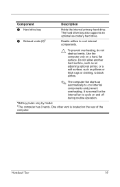
... cool internal components and prevent overheating. One other vent is normal for the internal fan to cycle on the rear of the computer. Notebook Tour 18 Do not allow another hard surface, such as an adjoining optional printer, or a soft surface, such as pillows or thick ...Component Description 4 Hard drive bay 5 Exhaust vents (2)† Holds the internal primary hard drive. It is located on and off during routine operation. *Battery packs vary by model. †The computer has 3 vents. Use the computer only on a hard, flat surface. The hard drive bay also supports...
... cool internal components and prevent overheating. One other vent is normal for the internal fan to cycle on the rear of the computer. Notebook Tour 18 Do not allow another hard surface, such as an adjoining optional printer, or a soft surface, such as pillows or thick ...Component Description 4 Hard drive bay 5 Exhaust vents (2)† Holds the internal primary hard drive. It is located on and off during routine operation. *Battery packs vary by model. †The computer has 3 vents. Use the computer only on a hard, flat surface. The hard drive bay also supports...

Notebook Tour Guide
Page 23
Additional hardware components Component Description 1 AC adapter Converts AC power to DC power. 2 Power cord* Connects an AC adapter to an AC outlet. 3 Battery pack* Powers the computer when it is not plugged into external power. *Battery packs and power cords vary in appearance by region and country. Notebook Tour 21
Additional hardware components Component Description 1 AC adapter Converts AC power to DC power. 2 Power cord* Connects an AC adapter to an AC outlet. 3 Battery pack* Powers the computer when it is not plugged into external power. *Battery packs and power cords vary in appearance by region and country. Notebook Tour 21

Notebook Tour Guide
Page 28
... key, Windows 2 audio-in (microphone) jack 14 audio-out (headphone) jack 14 B battery bay 22 battery light, identifying 10 battery pack release latch 17 battery pack, identifying 21 bays battery 17, 22 hard drive 18 buttons calculator 8 DVD 6 Media 7 mute 7 optical drive 14 PC Card slot eject 16 power 5 TouchPad 3 volume 7 wireless 4 C cables RJ-11 (modem... module 17 components bottom 17 display 19 front 11 left-side 15 rear 12 right-side 14 top 2 connectors power 15 cord, power, identifying 21 Notebook Tour Index-1
... key, Windows 2 audio-in (microphone) jack 14 audio-out (headphone) jack 14 B battery bay 22 battery light, identifying 10 battery pack release latch 17 battery pack, identifying 21 bays battery 17, 22 hard drive 18 buttons calculator 8 DVD 6 Media 7 mute 7 optical drive 14 PC Card slot eject 16 power 5 TouchPad 3 volume 7 wireless 4 C cables RJ-11 (modem... module 17 components bottom 17 display 19 front 11 left-side 15 rear 12 right-side 14 top 2 connectors power 15 cord, power, identifying 21 Notebook Tour Index-1

Notebook Tour Guide
Page 29
... Digital Media Slot light 15 Digital Media Slot, location 16 display release latch 11, 19 display switch, identifying 4 drives, optical 14 DVD button 6 E eject button, PC Card slot 16 environmental specifications 23 exhaust vents 13, 18 expansion port 2 15, 25 ExpressCard slot 14 external monitor port 15 F fn key 2 function keys... applications 2 Windows logo 2 L labels Bluetooth 22 Microsoft Certificate of Authenticity 22 modem approval 22 regulatory 22 service tag 22 wireless certification 22 WLAN 22 latches battery pack release 17 display release 11, 19 Notebook Tour Index-2
... Digital Media Slot light 15 Digital Media Slot, location 16 display release latch 11, 19 display switch, identifying 4 drives, optical 14 DVD button 6 E eject button, PC Card slot 16 environmental specifications 23 exhaust vents 13, 18 expansion port 2 15, 25 ExpressCard slot 14 external monitor port 15 F fn key 2 function keys... applications 2 Windows logo 2 L labels Bluetooth 22 Microsoft Certificate of Authenticity 22 modem approval 22 regulatory 22 service tag 22 wireless certification 22 WLAN 22 latches battery pack release 17 display release 11, 19 Notebook Tour Index-2

Notebook Tour Guide
Page 30
lights battery 10 caps lock 9 Digital Media Slot 15 IDE drive 10 mute 10 num lock 10 power 9 wireless 9, 13 lock, security cable 12 M Media button 7 memory ... 23 operating system Microsoft Certificate of Authenticity label 22 Product Key 22 optical drive button 14 optical drive, identifying 14 optional power adapter 15 P PC Card slot 16 PC Card slot eject button 16 ports 1394 15 expansion port 2 15 external monitor 15 USB 14, 15 power button 5 power connector 15 power...
lights battery 10 caps lock 9 Digital Media Slot 15 IDE drive 10 mute 10 num lock 10 power 9 wireless 9, 13 lock, security cable 12 M Media button 7 memory ... 23 operating system Microsoft Certificate of Authenticity label 22 Product Key 22 optical drive button 14 optical drive, identifying 14 optional power adapter 15 P PC Card slot 16 PC Card slot eject button 16 ports 1394 15 expansion port 2 15 external monitor 15 USB 14, 15 power button 5 power connector 15 power...
Notebook Tour Guide
Page 31
... input power specifications 24 regulatory information modem approval label 22 regulatory label 22 wireless certification labels 22 release latch battery pack 17 display 11, 19 RJ-11 (modem) jack 12 RJ-45 (network) jack 15 S scrolling... cable slot 12 serial number, computer 22 service tag 22 slots Digital Media 16 ExpressCard 14 memory module 17 PC Card 16 security cable 12 SmartMedia (SM) card 16 speakers 11 specifications operating environment 23 rated input power 24...wireless button 4 wireless certification label 22 wireless light 9, 13 WLAN label 22 X xD-Picture Card 16 Notebook Tour Index-4
... input power specifications 24 regulatory information modem approval label 22 regulatory label 22 wireless certification labels 22 release latch battery pack 17 display 11, 19 RJ-11 (modem) jack 12 RJ-45 (network) jack 15 S scrolling... cable slot 12 serial number, computer 22 service tag 22 slots Digital Media 16 ExpressCard 14 memory module 17 PC Card 16 security cable 12 SmartMedia (SM) card 16 speakers 11 specifications operating environment 23 rated input power 24...wireless button 4 wireless certification label 22 wireless light 9, 13 WLAN label 22 X xD-Picture Card 16 Notebook Tour Index-4

Touchpad and Keyboard
Page 13
... hotkey increases the brightness of the computer screen. Before you hold down the fn+f8 hotkey, the more the screen dims. Decreasing screen brightness conserves battery power. The longer you can use QuickLock, press fn+f6 to enter your Windows user password or your information by displaying the operating system Log...
... hotkey increases the brightness of the computer screen. Before you hold down the fn+f8 hotkey, the more the screen dims. Decreasing screen brightness conserves battery power. The longer you can use QuickLock, press fn+f6 to enter your Windows user password or your information by displaying the operating system Log...

Maintenance and Service Guide
Page 5
... 5.1 Serial Number 5-2 5.2 Disassembly Sequence Chart 5-3 5.3 Preparing the Computer for Disassembly 5-5 5.4 Hard Drive 5-7 5.5 Computer Feet 5-11 5.6 Memory Module 5-12 5.7 Mini PCI Communications Module 5-16 5.8 RTC Battery 5-18 5.9 Optical Drive 5-20 5.10 Switch Cover 5-22 5.11 Keyboard Assembly Frame 5-24 5.12 LED Board 5-28 5.13 Keyboard 5-30 5.14 Display Assembly 5-32 5.15...57 5.18 Modem Connector Cable 5-60 5.19 USB Board 5-62 5.20 Speakers 5-64 5.21 Heat Sink 5-67 5.22 Processor 5-70 5.23 Fan Assembly 5-72 5.24 PC Card Assembly 5-76 Maintenance and Service Guide v
... 5.1 Serial Number 5-2 5.2 Disassembly Sequence Chart 5-3 5.3 Preparing the Computer for Disassembly 5-5 5.4 Hard Drive 5-7 5.5 Computer Feet 5-11 5.6 Memory Module 5-12 5.7 Mini PCI Communications Module 5-16 5.8 RTC Battery 5-18 5.9 Optical Drive 5-20 5.10 Switch Cover 5-22 5.11 Keyboard Assembly Frame 5-24 5.12 LED Board 5-28 5.13 Keyboard 5-30 5.14 Display Assembly 5-32 5.15...57 5.18 Modem Connector Cable 5-60 5.19 USB Board 5-62 5.20 Speakers 5-64 5.21 Heat Sink 5-67 5.22 Processor 5-70 5.23 Fan Assembly 5-72 5.24 PC Card Assembly 5-76 Maintenance and Service Guide v


