HP Model 715/64 - Workstation Support and Manuals
Get Help and Manuals for this Hewlett-Packard item

View All Support Options Below
Free HP Model 715/64 manuals!
Problems with HP Model 715/64?
Ask a Question
Free HP Model 715/64 manuals!
Problems with HP Model 715/64?
Ask a Question
Most Recent HP Model 715/64 Questions

Replacement Cartridges
Can a HP 64x toner cartridge be converted to a 64a
Can a HP 64x toner cartridge be converted to a 64a
(Posted by droy23142 10 years ago)
Popular HP Model 715/64 Manual Pages
hp 9000 series 700 model 715 workstations service handbook (a2600-90039) - Page 12
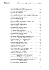
... 5-40 5-41 Installing Memory Boards 5-41 5-42 Disconnecting the PCX-T Grounding Wire 5-42 5-43 Disconnecting the PCX-T Module 5-43 5-44 Removing the PCX-T Module 5-44 5-45 Removing the Processor Board 5-46 5-46 Component and Internal Connector Locations
Model 715/C, 715/33, and 715/50 5-47 5-47 Component and Internal Connector Locations
Model 715/64, 715/80, 715/100, 715/100XC . . 5-48...
hp 9000 series 700 model 715 workstations service handbook (a2600-90039) - Page 14

... controls, connectors, and indicators
Product Description
The HP 9000 Series 700 Model 715 workstation uses one or two hard disk drives of the HP-UX operating system:
S Model 715/33, 715/50, and 715/C workstations use version 9.01 or later
S Model 715/75 workstations use version 9.03 or later
S Model 715/64, 715/80, 715/100, and 715/100XC workstations use version 9.05
or later
The Model 715...
hp 9000 series 700 model 715 workstations service handbook (a2600-90039) - Page 20

... Rear Panel Connectors
This section describes the following connectors on the system unit's rear panel:
S SCSI connector S HP parallel I/O connector S HP-HIL connector (Model 715/C, 715/33, 715/50, and 715/75 workstations) S 10-pin modular jack (Model 715/64, 715/80, 715/100, and 715/100XC
workstations)
S RS-232 serial input/output connectors S 802.3 network connector S Built-in graphics connector...
hp 9000 series 700 model 715 workstations service handbook (a2600-90039) - Page 21

...
Modular Jack HP Parallel Connector
SCSI Connector
Power Switch
Transfer of Control (TOC) Switch
Built-In Graphics Connector
Graphics Configuration Switches*
Optional Connector for EISA, CRX, or HCRX Graphics
Audio Line OUT Connector
*These switches are autoconfiguring. Figure 1-3. System Unit Rear Panel Connectors
1-8 Product Information
Model 715/64, 715/80, 715/100, and 715/100XC...
hp 9000 series 700 model 715 workstations service handbook (a2600-90039) - Page 22
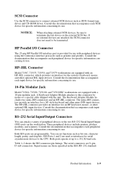
.../Output Connectors
You can set functions such as printers and plotters. HP Parallel I/O Connector
The 25-pin HP Parallel I/O interface port is provided for specific information concerning its use with a 10-pin modular jack. Consult the documentation that accompanies each SCSI device for use .
10-Pin Modular Jack
Model 715/64, 715/80, 715/100, and 715/100XC workstations are 9-pin...
hp 9000 series 700 model 715 workstations service handbook (a2600-90039) - Page 33
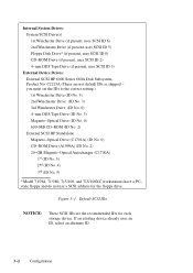
... device already uses an ID, select an alternate ID.
3-2 Configuration you must set the IDs to the correct setting.) 1st Winchester Drive (ID No. 4) 2nd Winchester Drive (ID No. 3)...HP Standalone Magneto-Optical Drive (C1701A) (ID No. 0) CD-ROM Drive (A1999A) (ID No. 2) 20-GB Magneto-Optical Autochanger (C1700A) 1st (ID No. 3) 2nd (ID No. 4) 3rd (ID No. 5)
*Model 715/64, 715/80, 715/100, and 715...
hp 9000 series 700 model 715 workstations service handbook (a2600-90039) - Page 56

... left, indicate system status and error codes. If an error occurs during the power-up . Figure 4-1 shows the location of Model 715/64, 715/80, , 715/100, and 715/100XC workstations. Front Panel LEDs
Table 4-1 through 8, right to determine the failing component.
4-2
Troubleshooting LED Error Codes
This section contains information about the error codes displayed by the LEDs on the front...
hp 9000 series 700 model 715 workstations service handbook (a2600-90039) - Page 68

...command.
4-14 Troubleshooting S Set or display the real-time clock value using the DATE command (this command is failing to appear on Model 715/64, 715/80, , 715/100, and 715/100XC workstations).
Recheck...not supported on the screen.
Boot Administration Environment
The Boot Console User Interface provides an "autoselect" or "interactive" environment after the power-on sequence. S Set ...
hp 9000 series 700 model 715 workstations service handbook (a2600-90039) - Page 69
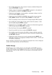
... is not supported on the System card using the SEARCH command.
S Set or display secure boot mode or the ability to the HELP command. Syntax checking is disabled using the SHOW command (this value. Troubleshooting 4-15
S Display the model number, version numbers, and jumper settings on Model 715/64, 715/80, , 715/100, and 715/100XC workstations). S Display the results...
hp 9000 series 700 model 715 workstations service handbook (a2600-90039) - Page 88

... Support
n
6 A2084-66002 EISA Interface Board
n
7 A2084-69511 Processor Board Model 715/33
e
A2084-69510 Processor Board Model 715/50
e
A4022-69516 Processor Board Model 715/64
e
A2084-69014 Motherboard Model 715/75
e
A4022-69518 Processor Board Model 715/80
e
A2084-69017 Motherboard Model 715/C
e
A4022-69510 Processor Board Model 715/100
e
A4022-69515 Processor Board Model 715...
hp 9000 series 700 model 715 workstations service handbook (a2600-90039) - Page 90

...-84007 Model 715/75 Logo Label
n
* A4022-84001 Model 715/64 Logo Label
n
* A4022-84005 Model 715/80 Logo Label
n
* A4022-84004 Model 715/100 Logo Label
n
* = not shown in Figure 5-1
Table 5-2. Observe the notices and prerequisites for removing each FRU. to Monitor n
* A2091-62004 CRX-48Z Graphics Proc. Replacement is the reverse of removal, unless noted.
Proc. Part Number...
hp 9000 series 700 model 715 workstations service handbook (a2600-90039) - Page 98
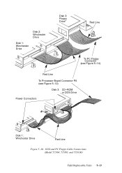
Disk 2: Winchester Drive
Disk 1: Winchester Drive
Disk 3: Floppy Drive*
Red Line
To PC Floppy Connector (see Figure 5-14)
Red Line
To Processor Board Connector P8 (see Figure 5-12)
Disk 3: CD-ROM or DDS Drive
Power Connectors
Disk 1: Winchester Drive
Red Line
Figure 5-10. SCSI and PC Floppy Cable Connections (Model 715/64, 715/80, and 715/100)
Field Replaceable Units 5-13
hp 9000 series 700 model 715 workstations service handbook (a2600-90039) - Page 101
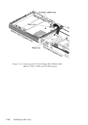
Connect cable here Red Line
Red Line Figure 5-14. Connecting the PC-Style Floppy Drive Ribbon Cable
(Model 715/64, 715/80, and 715/100 Systems)
5-16 Field Replaceable Units
hp 9000 series 700 model 715 workstations service handbook (a2600-90039) - Page 133

Component and Internal Connector Locations Model 715/64, 715/80, 715/100, 715/100XC
5-48 Field Replaceable Units Reserved
Calendar
Power Supply
Battery
Connector (P7)
(Location B1) PC Floppy
Connector (J2)
SCSI Cable Connector (P3)
Memory Slots
Rear Audio Board Connector (P15) ...
hp 9000 series 700 model 715 workstations service handbook (a2600-90039) - Page 140
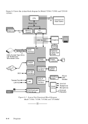
System Unit Functional Block Diagram Model 715/64, 715/80, 715/100, and 715/100XC
6-4 Diagrams Figure 6-3 hows the system block diagram for Model 715/64, 715/80, and 715/100 systems.
CPU PBUS 32
32
32
Instruction & Data Cache
Memory
Memory
72
Control
I/O Control
GSC System
Graphics
SCSI-2 Bus
8 DDS-Format Tape Drive CD-ROM Drive Winchester Drive
SCSI Interface
Parallel Interface
...
HP Model 715/64 Reviews
We have not received any reviews for HP yet.