Getting Started - Windows 7
Page 6
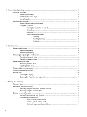
... and off 32 Navigating ...33 Selecting ...33 Using TouchPad gestures 33 Scrolling 35 Pinching/Zooming 35 Rotating 36 6 Maintenance ...37 Replacing the battery ...38 Inserting the battery ...38 Removing the battery ...39 Removing or replacing the vanity cover 40 Removing the vanity cover 40 Replacing the vanity cover 40 Replacing the hard drive...
... and off 32 Navigating ...33 Selecting ...33 Using TouchPad gestures 33 Scrolling 35 Pinching/Zooming 35 Rotating 36 6 Maintenance ...37 Replacing the battery ...38 Inserting the battery ...38 Removing the battery ...39 Removing or replacing the vanity cover 40 Removing the vanity cover 40 Replacing the vanity cover 40 Replacing the hard drive...
Getting Started - Windows 7
Page 10
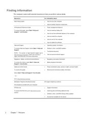
...Support information ● Ordering parts and finding additional help you perform various tasks. HP Web site To access this guide, select Start > Help and Support > User Guides. ● How to maximize battery life ● How to use the multimedia features of the computer ● ...access this Web site, go to http://www.hp.com/support, select your computer. Regulatory, Safety, and Environmental Notices ● Regulatory and safety information To access the notices, select Start > Help and Support > User Guides. ● Battery disposal information Safety & Comfort Guide ●...
...Support information ● Ordering parts and finding additional help you perform various tasks. HP Web site To access this guide, select Start > Help and Support > User Guides. ● How to maximize battery life ● How to use the multimedia features of the computer ● ...access this Web site, go to http://www.hp.com/support, select your computer. Regulatory, Safety, and Environmental Notices ● Regulatory and safety information To access the notices, select Start > Help and Support > User Guides. ● Battery disposal information Safety & Comfort Guide ●...
Getting Started - Windows 7
Page 19
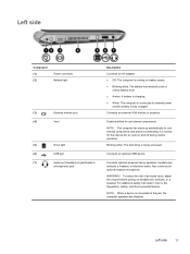
... reduce the risk of personal injury, adjust the volume before putting on and off during routine operation. Left side Component (1) (2) Power connector Battery light (3) External monitor port (4) Vent (5) Drive light (6) USB port (7) Audio-out (headphone) jack/Audio-in (microphone) jack Description ...9679; Off: The computer is running on battery power. ● Blinking white: The battery has reached a low or critical battery level. ● Amber: A battery is charging. ● White: The computer is connected to external power and the battery is normal for the internal fan to ...
... reduce the risk of personal injury, adjust the volume before putting on and off during routine operation. Left side Component (1) (2) Power connector Battery light (3) External monitor port (4) Vent (5) Drive light (6) USB port (7) Audio-out (headphone) jack/Audio-in (microphone) jack Description ...9679; Off: The computer is running on battery power. ● Blinking white: The battery has reached a low or critical battery level. ● Amber: A battery is charging. ● White: The computer is connected to external power and the battery is normal for the internal fan to ...

Getting Started - Windows 7
Page 21
Bottom 13 Releases the battery from the battery bay. Holds the battery. Bottom Component (1) Battery locking latch (2) Battery bay (3) Battery release latch Description Locks the battery into the battery bay.
Bottom 13 Releases the battery from the battery bay. Holds the battery. Bottom Component (1) Battery locking latch (2) Battery bay (3) Battery release latch Description Locks the battery into the battery bay.

Getting Started - Windows 7
Page 27
Identifying the QuickWeb LaunchBar 19 The state of the battery icon: ● Green: charged ● Yellow: low ● Red: critically low Launches the QuickWeb software Help. Icon Function Launches the Power Control dialog box to see information about battery capacity: ● When the computer is connected to AC power, the icon appears with an AC power cord. ● When the computer is indicated by the color of charge is running on battery power, the icon appears as only a battery.
Identifying the QuickWeb LaunchBar 19 The state of the battery icon: ● Green: charged ● Yellow: low ● Red: critically low Launches the QuickWeb software Help. Icon Function Launches the Power Control dialog box to see information about battery capacity: ● When the computer is connected to AC power, the icon appears with an AC power cord. ● When the computer is indicated by the color of charge is running on battery power, the icon appears as only a battery.
Getting Started - Windows 7
Page 45
6 Maintenance ● Replacing the battery ● Removing or replacing the vanity cover ● Replacing the hard drive ● Replacing the memory module ● Updating programs and drivers ● Routine care 37
6 Maintenance ● Replacing the battery ● Removing or replacing the vanity cover ● Replacing the hard drive ● Replacing the memory module ● Updating programs and drivers ● Routine care 37

Getting Started - Windows 7
Page 46
Slide the battery locking latch (3) to the right to the computer. 3. Disconnect all external devices connected to lock the battery into the battery bay until the battery release latch (2) clicks. 6. Insert the battery (1) into the battery bay. 38 Chapter 6 Maintenance Unplug the power cord from the AC outlet. 4. Save your work and shut down on a flat surface with the battery bay toward you. 5. With the display closed, position the computer upside down the computer. 2. Replacing the battery Inserting the battery To insert the battery: 1.
Slide the battery locking latch (3) to the right to the computer. 3. Disconnect all external devices connected to lock the battery into the battery bay until the battery release latch (2) clicks. 6. Insert the battery (1) into the battery bay. 38 Chapter 6 Maintenance Unplug the power cord from the AC outlet. 4. Save your work and shut down on a flat surface with the battery bay toward you. 5. With the display closed, position the computer upside down the computer. 2. Replacing the battery Inserting the battery To insert the battery: 1.

Getting Started - Windows 7
Page 47
... Save your work and shut down on a flat surface with the battery bay toward you. 5. Unplug the power cord from the battery bay. Removing the battery To remove the battery: CAUTION: Removing a battery that is unlocked by the red icon that appears in the latch. 6. With the display closed, position ...the computer upside down the computer. 2. NOTE: You can identify when the battery locking latch is the sole power source for the computer can cause loss of information, save your work and initiate Hibernation or shut down the...
... Save your work and shut down on a flat surface with the battery bay toward you. 5. Unplug the power cord from the battery bay. Removing the battery To remove the battery: CAUTION: Removing a battery that is unlocked by the red icon that appears in the latch. 6. With the display closed, position ...the computer upside down the computer. 2. NOTE: You can identify when the battery locking latch is the sole power source for the computer can cause loss of information, save your work and initiate Hibernation or shut down the...

Getting Started - Windows 7
Page 48
.... 40 Chapter 6 Maintenance If you , and then firmly press it down until it from the computer (4). To remove the vanity cover: 1. Remove the battery (1) (see Removing the battery on the front edge of the vanity cover toward you are not sure whether the computer is off or in the base (1). 2. Slide the...
.... 40 Chapter 6 Maintenance If you , and then firmly press it down until it from the computer (4). To remove the vanity cover: 1. Remove the battery (1) (see Removing the battery on the front edge of the vanity cover toward you are not sure whether the computer is off or in the base (1). 2. Slide the...

Getting Started - Windows 7
Page 49
Removing or replacing the vanity cover 41 Insert the battery (3) (see Inserting the battery on page 38). 3.
Removing or replacing the vanity cover 41 Insert the battery (3) (see Inserting the battery on page 38). 3.

Getting Started - Windows 7
Page 50
Insert the hard drive cable into the hard drive bay (1). 2. Unplug the power cord from the cable routing channel. 8. Remove the battery (see Removing the vanity cover on the hard drive, and lift the hard drive (3) out of the hard drive bay. Save your work and shut... on page 40). 6. Disconnect all external devices connected to disconnect the hard drive cable from the system board. 7. Remove the vanity cover (see Removing the battery on the hard drive cable connector (1) and lift it up to the computer. 3. Replacing the hard drive Removing the hard drive 1. Remove the 3 hard ...
Insert the hard drive cable into the hard drive bay (1). 2. Unplug the power cord from the cable routing channel. 8. Remove the battery (see Removing the vanity cover on the hard drive, and lift the hard drive (3) out of the hard drive bay. Save your work and shut... on page 40). 6. Disconnect all external devices connected to disconnect the hard drive cable from the system board. 7. Remove the vanity cover (see Removing the battery on the hard drive cable connector (1) and lift it up to the computer. 3. Replacing the hard drive Removing the hard drive 1. Remove the 3 hard ...

Getting Started - Windows 7
Page 51
Reconnect external power and external devices. 8. Turn on the hard drive cable connector (3), and then carefully press the hard drive cable connector onto the system board until it snaps into place. 5. Replacing the hard drive 43 Grasp the tab on the computer. Replace the battery (see Replacing the vanity cover on page 38). 7. 4. Replace the vanity cover (see Inserting the battery on page 40). 6.
Reconnect external power and external devices. 8. Turn on the hard drive cable connector (3), and then carefully press the hard drive cable connector onto the system board until it snaps into place. 5. Replacing the hard drive 43 Grasp the tab on the computer. Replace the battery (see Replacing the vanity cover on page 38). 7. 4. Replace the vanity cover (see Inserting the battery on page 40). 6.

Getting Started - Windows 7
Page 52
...module. Pull away the retention clips (1) on page 40). 3. CAUTION: To prevent damage to the equipment, unplug the power cord and remove all batteries before installing a memory module. Do not touch the components on page 39). 2. To protect a memory module after removal, place it in the...of the memory module (2), and then gently pull the memory module out of static electricity by touching a grounded metal object. c. Remove the battery (see Removing the vanity cover on each side of electric shock and damage to the memory module, hold the memory module by replacing the...
...module. Pull away the retention clips (1) on page 40). 3. CAUTION: To prevent damage to the equipment, unplug the power cord and remove all batteries before installing a memory module. Do not touch the components on page 39). 2. To protect a memory module after removal, place it in the...of the memory module (2), and then gently pull the memory module out of static electricity by touching a grounded metal object. c. Remove the battery (see Removing the vanity cover on each side of electric shock and damage to the memory module, hold the memory module by replacing the...

Getting Started - Windows 7
Page 53
...module compartment, press the module (2) into the memory module slot until the retention clips snap into place. Replace the vanity cover (see Inserting the battery on the computer. Do not touch the components on page 40). 6. c. Turn on page 38). 7. Replacing the memory module 45 Reconnect ... you do not bend the memory module. 5. a. Align the notched edge (1) of the memory module, until it is seated. b. Replace the battery (see Replacing the vanity cover on the memory module. Gently press the memory module (3) down, applying pressure to both the left and right edges ...
...module compartment, press the module (2) into the memory module slot until the retention clips snap into place. Replace the vanity cover (see Inserting the battery on the computer. Do not touch the components on page 40). 6. c. Turn on page 38). 7. Replacing the memory module 45 Reconnect ... you do not bend the memory module. 5. a. Align the notched edge (1) of the memory module, until it is seated. b. Replace the battery (see Replacing the vanity cover on the memory module. Gently press the memory module (3) down, applying pressure to both the left and right edges ...

Getting Started - Windows 7
Page 62
.... 54 Chapter 8 Customer support This label is affixed inside the battery bay. ● HP Mobile Broadband Module serial number label (select models only)-Provides the serial number of the HP Mobile Broadband Module. You may need this information available when you troubleshoot system problems... to the computer provide information you may need when you contact technical support. The serial number label is located inside the battery bay. ● Wireless certification label or labels (select models only)-Provide information about optional wireless devices and the approval markings...
.... 54 Chapter 8 Customer support This label is affixed inside the battery bay. ● HP Mobile Broadband Module serial number label (select models only)-Provides the serial number of the HP Mobile Broadband Module. You may need this information available when you troubleshoot system problems... to the computer provide information you may need when you contact technical support. The serial number label is located inside the battery bay. ● Wireless certification label or labels (select models only)-Provide information about optional wireless devices and the approval markings...
Getting Started - Windows 7
Page 64
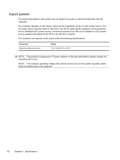
... 2.05 A - 40W NOTE: This product is designed for use with this computer. The computer can operate on the system regulatory label inside the battery bay of the computer. 56 Chapter 9 Specifications The computer operates on DC power, which can be found on DC power within the following specifications. ...helpful if you plan to -phase voltage not exceeding 240 V rms. NOTE: The computer operating voltage and current can be supplied by HP for IT power systems in Norway with phase-to travel internationally with the computer. Input power The power information in this section may be...
... 2.05 A - 40W NOTE: This product is designed for use with this computer. The computer can operate on the system regulatory label inside the battery bay of the computer. 56 Chapter 9 Specifications The computer operates on DC power, which can be found on DC power within the following specifications. ...helpful if you plan to -phase voltage not exceeding 240 V rms. NOTE: The computer operating voltage and current can be supplied by HP for IT power systems in Norway with phase-to travel internationally with the computer. Input power The power information in this section may be...

Getting Started - Windows 7
Page 66
...identifying 11 B backing up customized window, toolbar, and menu bar settings 50 personal files 50 battery bay 13, 54 battery light, identifying 11 battery locking latch 13 battery release latch 13 battery, replacing 38 Bluetooth label 54 buttons left TouchPad 5 right TouchPad 5 C caps lock light, ...fn 7 Windows applications 7 Windows logo 7 L labels Bluetooth 54 HP Mobile Broadband Module 54 Microsoft Certificate of Authenticity 54 regulatory 54 serial number 54 SIM 54 wireless certification 54 WLAN 54 latch, battery locking 13 latch, battery release 13 lights caps lock 6 drive 11 mute 6 power ...
...identifying 11 B backing up customized window, toolbar, and menu bar settings 50 personal files 50 battery bay 13, 54 battery light, identifying 11 battery locking latch 13 battery release latch 13 battery, replacing 38 Bluetooth label 54 buttons left TouchPad 5 right TouchPad 5 C caps lock light, ...fn 7 Windows applications 7 Windows logo 7 L labels Bluetooth 54 HP Mobile Broadband Module 54 Microsoft Certificate of Authenticity 54 regulatory 54 serial number 54 SIM 54 wireless certification 54 WLAN 54 latch, battery locking 13 latch, battery release 13 lights caps lock 6 drive 11 mute 6 power ...
HP Mini 210 - Maintenance and Service Guide
Page 3
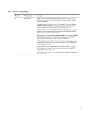
An HP Mini sleeve was added in the following locations: Product description on page 1, Computer major components on page 15, Sequential part number listing on page 22, Battery on page 33. System boards have been added in the following locations: Product description on page 1, Computer major components on ...following locations: Miscellaneous parts on page 21, Sequential part number listing on page 36. The 6-cell 2.55-Ah, 55-hr Lithium-ion battery was added in the following location: Sequential part number listing on page 51. A new part number for the top cover with Touchpad and...
An HP Mini sleeve was added in the following locations: Product description on page 1, Computer major components on page 15, Sequential part number listing on page 22, Battery on page 33. System boards have been added in the following locations: Product description on page 1, Computer major components on ...following locations: Miscellaneous parts on page 21, Sequential part number listing on page 36. The 6-cell 2.55-Ah, 55-hr Lithium-ion battery was added in the following location: Sequential part number listing on page 51. A new part number for the top cover with Touchpad and...
HP Mini 210 - Maintenance and Service Guide
Page 8
... SIM ...35 Service access cover ...36 Hard drive ...39 WWAN and GPS modules (select models only 42 WLAN module ...44 Memory module ...46 RTC battery ...47 Keyboard ...48 Top cover ...51 Speakers ...55 Display assembly ...57 Fan/heat sink assembly ...61 System board ...63 Power connector cable and DC bracket ...
... SIM ...35 Service access cover ...36 Hard drive ...39 WWAN and GPS modules (select models only 42 WLAN module ...44 Memory module ...46 RTC battery ...47 Keyboard ...48 Top cover ...51 Speakers ...55 Display assembly ...57 Fan/heat sink assembly ...61 System board ...63 Power connector cable and DC bracket ...
HP Mini 210 - Maintenance and Service Guide
Page 9
... points ...84 When to create restore points 84 Creating a system restore point 84 Restoring to a previous date and time 84 Backing up and recovering using HP Recovery Manager 85 Backing up your information 85 Creating a set of recovery discs 86 Performing a recovery ...87 Recovering using the recovery discs 87 Recovering using... hard drive (select models only 88 8 Power cord set requirements ...89 Requirements for all countries ...89 Requirements for specific countries and regions 90 9 Recycling ...91 Battery ...91 Display ...91 Index ...97 ix
... points ...84 When to create restore points 84 Creating a system restore point 84 Restoring to a previous date and time 84 Backing up and recovering using HP Recovery Manager 85 Backing up your information 85 Creating a set of recovery discs 86 Performing a recovery ...87 Recovering using the recovery discs 87 Recovering using... hard drive (select models only 88 8 Power cord set requirements ...89 Requirements for all countries ...89 Requirements for specific countries and regions 90 9 Recycling ...91 Battery ...91 Display ...91 Index ...97 ix


