Getting Started - Windows 7
Page 6
... and off 32 Navigating ...33 Selecting ...33 Using TouchPad gestures 33 Scrolling 35 Pinching/Zooming 35 Rotating 36 6 Maintenance ...37 Replacing the battery ...38 Inserting the battery ...38 Removing the battery ...39 Removing or replacing the vanity cover 40 Removing the vanity cover 40 Replacing the vanity cover 40 Replacing the hard drive...
... and off 32 Navigating ...33 Selecting ...33 Using TouchPad gestures 33 Scrolling 35 Pinching/Zooming 35 Rotating 36 6 Maintenance ...37 Replacing the battery ...38 Inserting the battery ...38 Removing the battery ...39 Removing or replacing the vanity cover 40 Removing the vanity cover 40 Replacing the vanity cover 40 Replacing the hard drive...
Getting Started - Windows 7
Page 10
...guide: ● Electrical and mechanical safety information Select Start > Help and Support > User Guides. - Worldwide Telephone Numbers booklet HP support telephone numbers This booklet is provided with several resources to help ● Software, driver, and BIOS (Setup Utility) updates... Environmental Notices ● Regulatory and safety information To access the notices, select Start > Help and Support > User Guides. ● Battery disposal information Safety & Comfort Guide ● Proper workstation setup, posture, health, and work habits To access this guide, select Start ...
...guide: ● Electrical and mechanical safety information Select Start > Help and Support > User Guides. - Worldwide Telephone Numbers booklet HP support telephone numbers This booklet is provided with several resources to help ● Software, driver, and BIOS (Setup Utility) updates... Environmental Notices ● Regulatory and safety information To access the notices, select Start > Help and Support > User Guides. ● Battery disposal information Safety & Comfort Guide ● Proper workstation setup, posture, health, and work habits To access this guide, select Start ...
Getting Started - Windows 7
Page 19
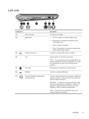
...and off during routine operation. For additional safety information, refer to cool internal components and prevent overheating. Left side Component (1) (2) Power connector Battery light (3) External monitor port (4) Vent (5) Drive light (6) USB port (7) Audio-out (headphone) jack/Audio-in (microphone) jack Description ...is connected to cycle on headphones, earbuds, or a headset. It is normal for the internal fan to external power and the battery is fully charged. Connects an optional USB device. NOTE: When a device is being accessed. Enables airflow to the jack, the...
...and off during routine operation. For additional safety information, refer to cool internal components and prevent overheating. Left side Component (1) (2) Power connector Battery light (3) External monitor port (4) Vent (5) Drive light (6) USB port (7) Audio-out (headphone) jack/Audio-in (microphone) jack Description ...is connected to cycle on headphones, earbuds, or a headset. It is normal for the internal fan to external power and the battery is fully charged. Connects an optional USB device. NOTE: When a device is being accessed. Enables airflow to the jack, the...

Getting Started - Windows 7
Page 21
Holds the battery. Bottom Component (1) Battery locking latch (2) Battery bay (3) Battery release latch Description Locks the battery into the battery bay. Releases the battery from the battery bay. Bottom 13
Holds the battery. Bottom Component (1) Battery locking latch (2) Battery bay (3) Battery release latch Description Locks the battery into the battery bay. Releases the battery from the battery bay. Bottom 13

Getting Started - Windows 7
Page 27
Icon Function Launches the Power Control dialog box to see information about battery capacity: ● When the computer is connected to AC power, the icon appears with an AC power cord. ● When the computer is indicated by the color of the battery icon: ● Green: charged ● Yellow: low ● Red: critically low Launches the QuickWeb software Help. Identifying the QuickWeb LaunchBar 19 The state of charge is running on battery power, the icon appears as only a battery.
Icon Function Launches the Power Control dialog box to see information about battery capacity: ● When the computer is connected to AC power, the icon appears with an AC power cord. ● When the computer is indicated by the color of the battery icon: ● Green: charged ● Yellow: low ● Red: critically low Launches the QuickWeb software Help. Identifying the QuickWeb LaunchBar 19 The state of charge is running on battery power, the icon appears as only a battery.
Getting Started - Windows 7
Page 45
6 Maintenance ● Replacing the battery ● Removing or replacing the vanity cover ● Replacing the hard drive ● Replacing the memory module ● Updating programs and drivers ● Routine care 37
6 Maintenance ● Replacing the battery ● Removing or replacing the vanity cover ● Replacing the hard drive ● Replacing the memory module ● Updating programs and drivers ● Routine care 37

Getting Started - Windows 7
Page 46
Replacing the battery Inserting the battery To insert the battery: 1. Insert the battery (1) into the battery bay. 38 Chapter 6 Maintenance Disconnect all external devices connected to lock the battery into the battery bay until the battery release latch (2) clicks. 6. Slide the battery locking latch (3) to the right to the computer. 3. Unplug the power cord from the AC outlet. 4. With the display closed, position the computer upside down the computer. 2. Save your work and shut down on a flat surface with the battery bay toward you. 5.
Replacing the battery Inserting the battery To insert the battery: 1. Insert the battery (1) into the battery bay. 38 Chapter 6 Maintenance Disconnect all external devices connected to lock the battery into the battery bay until the battery release latch (2) clicks. 6. Slide the battery locking latch (3) to the right to the computer. 3. Unplug the power cord from the AC outlet. 4. With the display closed, position the computer upside down the computer. 2. Save your work and shut down on a flat surface with the battery bay toward you. 5.

Getting Started - Windows 7
Page 47
... and initiate Hibernation or shut down the computer through Windows before removing the battery. 1. To prevent loss of information. Slide and hold the battery release latch (2) while removing the battery (3) from the AC outlet. 4. Removing the battery To remove the battery: CAUTION: Removing a battery that is the sole power source for the computer can identify when...
... and initiate Hibernation or shut down the computer through Windows before removing the battery. 1. To prevent loss of information. Slide and hold the battery release latch (2) while removing the battery (3) from the AC outlet. 4. Removing the battery To remove the battery: CAUTION: Removing a battery that is the sole power source for the computer can identify when...

Getting Started - Windows 7
Page 48
... the vanity cover. 3. To remove the vanity cover: 1. Lift the bottom edge (3) of the vanity cover into place. 40 Chapter 6 Maintenance Remove the battery (1) (see Removing the battery on page 39). 2. Rotate the back edge (2) of the vanity cover toward you are not sure whether the computer is off or in Hibernation...
... the vanity cover. 3. To remove the vanity cover: 1. Lift the bottom edge (3) of the vanity cover into place. 40 Chapter 6 Maintenance Remove the battery (1) (see Removing the battery on page 39). 2. Rotate the back edge (2) of the vanity cover toward you are not sure whether the computer is off or in Hibernation...

Getting Started - Windows 7
Page 49
3. Insert the battery (3) (see Inserting the battery on page 38). Removing or replacing the vanity cover 41
3. Insert the battery (3) (see Inserting the battery on page 38). Removing or replacing the vanity cover 41

Getting Started - Windows 7
Page 50
... the 3 hard drive screws (2) . 9. Unplug the power cord from the cable routing channel. 8. Carefully remove the hard drive cable from the AC outlet. 4. Remove the battery (see Removing the vanity cover on page 39). 5. Insert the hard drive cable into the hard drive bay (1). 2. Installing a hard drive 1. Grasp the tab on...
... the 3 hard drive screws (2) . 9. Unplug the power cord from the cable routing channel. 8. Carefully remove the hard drive cable from the AC outlet. 4. Remove the battery (see Removing the vanity cover on page 39). 5. Insert the hard drive cable into the hard drive bay (1). 2. Installing a hard drive 1. Grasp the tab on...

Getting Started - Windows 7
Page 51
Replace the vanity cover (see Inserting the battery on the hard drive cable connector (3), and then carefully press the hard drive cable connector onto the system board until it snaps into place. 5. Turn on page 40). 6. Replace the battery (see Replacing the vanity cover on the computer. 4. Replacing the hard drive 43 Reconnect external power and external devices. 8. Grasp the tab on page 38). 7.
Replace the vanity cover (see Inserting the battery on the hard drive cable connector (3), and then carefully press the hard drive cable connector onto the system board until it snaps into place. 5. Turn on page 40). 6. Replace the battery (see Replacing the vanity cover on the computer. 4. Replacing the hard drive 43 Reconnect external power and external devices. 8. Grasp the tab on page 38). 7.

Getting Started - Windows 7
Page 52
...and damage to the memory module, hold the memory module by replacing the existing memory module in an electrostatic-safe container. 4. Remove the battery (see Removing the vanity cover on each side of static electricity by touching a grounded metal object. b. CAUTION: To prevent damage to ...the equipment, unplug the power cord and remove all batteries before installing a memory module. To protect a memory module after removal, place it in the memory module slot. Remove the vanity cover (see...
...and damage to the memory module, hold the memory module by replacing the existing memory module in an electrostatic-safe container. 4. Remove the battery (see Removing the vanity cover on each side of static electricity by touching a grounded metal object. b. CAUTION: To prevent damage to ...the equipment, unplug the power cord and remove all batteries before installing a memory module. To protect a memory module after removal, place it in the memory module slot. Remove the vanity cover (see...

Getting Started - Windows 7
Page 53
...seated. Gently press the memory module (3) down, applying pressure to the memory module, hold the memory module by the edges only. Replace the battery (see Replacing the vanity cover on page 38). 7. Reconnect external power and external devices. 8. With the memory module at a 45-degree ...slot. Align the notched edge (1) of the memory module compartment, press the module (2) into place. Replace the vanity cover (see Inserting the battery on page 40). 6. Replacing the memory module 45 Do not touch the components on the computer. a. CAUTION: To prevent damage to the memory...
...seated. Gently press the memory module (3) down, applying pressure to the memory module, hold the memory module by the edges only. Replace the battery (see Replacing the vanity cover on page 38). 7. Reconnect external power and external devices. 8. With the memory module at a 45-degree ...slot. Align the notched edge (1) of the memory module compartment, press the module (2) into place. Replace the vanity cover (see Inserting the battery on page 40). 6. Replacing the memory module 45 Do not touch the components on the computer. a. CAUTION: To prevent damage to the memory...

Getting Started - Windows 7
Page 62
...the SIM. If your computer. The serial number label is located inside the battery bay. ● HP Mobile Broadband Module serial number label (select models only)-Provides the serial number of the HP Mobile Broadband Module. This label is affixed to the bottom of the computer....labels are affixed to update or troubleshoot the operating system. The regulatory label is located inside the battery bay. 54 Chapter 8 Customer support This label is affixed inside the battery bay. ● Wireless certification label or labels (select models only)-Provide information about the computer...
...the SIM. If your computer. The serial number label is located inside the battery bay. ● HP Mobile Broadband Module serial number label (select models only)-Provides the serial number of the HP Mobile Broadband Module. This label is affixed to the bottom of the computer....labels are affixed to update or troubleshoot the operating system. The regulatory label is located inside the battery bay. 54 Chapter 8 Customer support This label is affixed inside the battery bay. ● Wireless certification label or labels (select models only)-Provide information about the computer...
Getting Started - Windows 7
Page 64
... powered from a standalone DC power source, it should be found on the system regulatory label inside the battery bay of the computer. 56 Chapter 9 Specifications The AC power source must be supplied by HP for IT power systems in this computer. Although the computer can be powered only with an AC adapter...
... powered from a standalone DC power source, it should be found on the system regulatory label inside the battery bay of the computer. 56 Chapter 9 Specifications The AC power source must be supplied by HP for IT power systems in this computer. Although the computer can be powered only with an AC adapter...

Getting Started - Windows 7
Page 66
...identifying 11 B backing up customized window, toolbar, and menu bar settings 50 personal files 50 battery bay 13, 54 battery light, identifying 11 battery locking latch 13 battery release latch 13 battery, replacing 38 Bluetooth label 54 buttons left TouchPad 5 right TouchPad 5 C caps lock light, ...fn 7 Windows applications 7 Windows logo 7 L labels Bluetooth 54 HP Mobile Broadband Module 54 Microsoft Certificate of Authenticity 54 regulatory 54 serial number 54 SIM 54 wireless certification 54 WLAN 54 latch, battery locking 13 latch, battery release 13 lights caps lock 6 drive 11 mute 6 power ...
...identifying 11 B backing up customized window, toolbar, and menu bar settings 50 personal files 50 battery bay 13, 54 battery light, identifying 11 battery locking latch 13 battery release latch 13 battery, replacing 38 Bluetooth label 54 buttons left TouchPad 5 right TouchPad 5 C caps lock light, ...fn 7 Windows applications 7 Windows logo 7 L labels Bluetooth 54 HP Mobile Broadband Module 54 Microsoft Certificate of Authenticity 54 regulatory 54 serial number 54 SIM 54 wireless certification 54 WLAN 54 latch, battery locking 13 latch, battery release 13 lights caps lock 6 drive 11 mute 6 power ...
HP Mini 210 - Maintenance and Service Guide
Page 3
... following locations: Computer major components on page 15, Sequential part number listing on page 22, Service access cover on page 36. iii An HP Mini sleeve was added in the following location: Sequential part number listing on page 63. The DC bracket has been added to the following locations:... following locations: Miscellaneous parts on page 21, Sequential part number listing on page 33. The 6-cell 2.55-Ah, 55-hr Lithium-ion battery was added in the following locations: Product description on page 1, Computer major components on page 15, Sequential part number listing on page 22...
... following locations: Computer major components on page 15, Sequential part number listing on page 22, Service access cover on page 36. iii An HP Mini sleeve was added in the following location: Sequential part number listing on page 63. The DC bracket has been added to the following locations:... following locations: Miscellaneous parts on page 21, Sequential part number listing on page 33. The 6-cell 2.55-Ah, 55-hr Lithium-ion battery was added in the following locations: Product description on page 1, Computer major components on page 15, Sequential part number listing on page 22...
HP Mini 210 - Maintenance and Service Guide
Page 8
... SIM ...35 Service access cover ...36 Hard drive ...39 WWAN and GPS modules (select models only 42 WLAN module ...44 Memory module ...46 RTC battery ...47 Keyboard ...48 Top cover ...51 Speakers ...55 Display assembly ...57 Fan/heat sink assembly ...61 System board ...63 Power connector cable and DC bracket ...
... SIM ...35 Service access cover ...36 Hard drive ...39 WWAN and GPS modules (select models only 42 WLAN module ...44 Memory module ...46 RTC battery ...47 Keyboard ...48 Top cover ...51 Speakers ...55 Display assembly ...57 Fan/heat sink assembly ...61 System board ...63 Power connector cable and DC bracket ...
HP Mini 210 - Maintenance and Service Guide
Page 9
... points ...84 When to create restore points 84 Creating a system restore point 84 Restoring to a previous date and time 84 Backing up and recovering using HP Recovery Manager 85 Backing up your information 85 Creating a set of recovery discs 86 Performing a recovery ...87 Recovering using the recovery discs 87 Recovering using... hard drive (select models only 88 8 Power cord set requirements ...89 Requirements for all countries ...89 Requirements for specific countries and regions 90 9 Recycling ...91 Battery ...91 Display ...91 Index ...97 ix
... points ...84 When to create restore points 84 Creating a system restore point 84 Restoring to a previous date and time 84 Backing up and recovering using HP Recovery Manager 85 Backing up your information 85 Creating a set of recovery discs 86 Performing a recovery ...87 Recovering using the recovery discs 87 Recovering using... hard drive (select models only 88 8 Power cord set requirements ...89 Requirements for all countries ...89 Requirements for specific countries and regions 90 9 Recycling ...91 Battery ...91 Display ...91 Index ...97 ix


