
Mini User Guide - Windows XP
Page 81
... Broadband Module 31 HP Mobile Broadband, disabled 31 hubs 52 I icons network status 25 wireless 25 internal display switch, identifying 7 internal microphone, identifying 7, 36 Internet connection setup 28 J jacks audio-in (microphone) 6, 36 audio-out (headphone) 6, 36 RJ-45 (network) 5 K keyboard hotkeys, identifying 54 ...a power-on password 46 managing an administrator password 45 memory module inserting 61 removing 61 memory module compartment cover removing 61 replacing 62 memory module compartment, identifying 8 memory test 71 microphone (audio-in) jack 6, 36 monitor, connecting 41 mouse, ...
... Broadband Module 31 HP Mobile Broadband, disabled 31 hubs 52 I icons network status 25 wireless 25 internal display switch, identifying 7 internal microphone, identifying 7, 36 Internet connection setup 28 J jacks audio-in (microphone) 6, 36 audio-out (headphone) 6, 36 RJ-45 (network) 5 K keyboard hotkeys, identifying 54 ...a power-on password 46 managing an administrator password 45 memory module inserting 61 removing 61 memory module compartment cover removing 61 replacing 62 memory module compartment, identifying 8 memory test 71 microphone (audio-in) jack 6, 36 monitor, connecting 41 mouse, ...

Service Guide
Page 8
Equipment guidelines 41 Component replacement procedures 42 Service tag ...42 Device feet ...43 Battery ...44 SIM ...45 Memory module ...46 Keyboard ...48 RTC battery ...53 Mass storage devices ...54 Hard drive ...55 Solid-state drive 55 Top cover ...57 WLAN module ...60 WWAN module ...62 USB/...
Equipment guidelines 41 Component replacement procedures 42 Service tag ...42 Device feet ...43 Battery ...44 SIM ...45 Memory module ...46 Keyboard ...48 RTC battery ...53 Mass storage devices ...54 Hard drive ...55 Solid-state drive 55 Top cover ...57 WLAN module ...60 WWAN module ...62 USB/...
Service Guide
Page 14
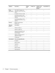
Category Description HP Mini 1101 Power requirements 30-W UMA AC adapter (non- √ Smart) with localized cable plug support AC adapter connector on cable √ 6-cell ... Windows Vista® Business 32 √ (with XP Pro image) HP Mobile Mi Serviceability End-user replaceable parts: AC adapter √ Battery (system) √ Hard drive √ Keyboard √ Memory module √ Solid-state drive √ HP Mini 110 HP Mini 110 by Studio Tord Boontje √ √ Compaq Mini 110 √ √ √ √ √ √ √ √ ...
Category Description HP Mini 1101 Power requirements 30-W UMA AC adapter (non- √ Smart) with localized cable plug support AC adapter connector on cable √ 6-cell ... Windows Vista® Business 32 √ (with XP Pro image) HP Mobile Mi Serviceability End-user replaceable parts: AC adapter √ Battery (system) √ Hard drive √ Keyboard √ Memory module √ Solid-state drive √ HP Mini 110 HP Mini 110 by Studio Tord Boontje √ √ Compaq Mini 110 √ √ √ √ √ √ √ √ ...
Service Guide
Page 41
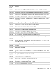
... Korea on black and blue models with Windows operating system installed 535689-B31 Keyboard for use only with international models on black and blue models with Windows operating system installed 535689-BB1 Keyboard for use only in Israel on black and blue models with Windows operating...only (contains 4 device feet) 537618-002 Rubber Kit for use with pink, white, and HP Mini 110 by Studio Tord Boontje models only (contains 4 device feet) 537619-001 Heat sink assembly (includes replacement thermal material) 537620-001 Screw Kit 537621-001 Speaker assembly (includes left and right cables) ...
... Korea on black and blue models with Windows operating system installed 535689-B31 Keyboard for use only with international models on black and blue models with Windows operating system installed 535689-BB1 Keyboard for use only in Israel on black and blue models with Windows operating...only (contains 4 device feet) 537618-002 Rubber Kit for use with pink, white, and HP Mini 110 by Studio Tord Boontje models only (contains 4 device feet) 537619-001 Heat sink assembly (includes replacement thermal material) 537620-001 Screw Kit 537621-001 Speaker assembly (includes left and right cables) ...
Service Guide
Page 42
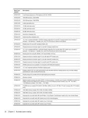
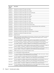
... replacement material for use on the following model numbers only: HP: 110-1000 - 110-1099 and Compaq: 110c-1000 - 110-1099) 512-MB memory module (PC2-5300, 533-MHz, DDR2, for use in HP Mini 110 and Compaq: Mini 110 models only) 1024-MB memory module (PC2-5300, 533-MHz, DDR2) 2048-MB memory module (PC2-5300, 533-MHz, DDR2) Keyboard...
... replacement material for use on the following model numbers only: HP: 110-1000 - 110-1099 and Compaq: 110c-1000 - 110-1099) 512-MB memory module (PC2-5300, 533-MHz, DDR2, for use in HP Mini 110 and Compaq: Mini 110 models only) 1024-MB memory module (PC2-5300, 533-MHz, DDR2) 2048-MB memory module (PC2-5300, 533-MHz, DDR2) Keyboard...
Service Guide
Page 44
...Keyboard for use with pink HP models only in Greece 538510-001 Display Screw Kit 571370-001 System board (includes Intel Atom N280 1.66-GHz processor, 512-KB Level 2 cache, 533-MHz front-side bus (FSB), and replacement thermal material) for use on the following model numbers only: HP: 110-1000 - 110...-1099 and Compaq: 110c-1000 - 110-1099 571414-001 10.1-inch, standard-definition, AntiGlare display assembly (includes WWAN) for ...
...Keyboard for use with pink HP models only in Greece 538510-001 Display Screw Kit 571370-001 System board (includes Intel Atom N280 1.66-GHz processor, 512-KB Level 2 cache, 533-MHz front-side bus (FSB), and replacement thermal material) for use on the following model numbers only: HP: 110-1000 - 110...-1099 and Compaq: 110c-1000 - 110-1099 571414-001 10.1-inch, standard-definition, AntiGlare display assembly (includes WWAN) for ...
Service Guide
Page 58
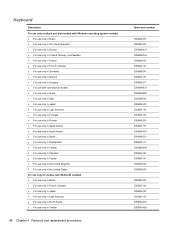
Keyboard Description For use only on black and blue models with Windows operating system installed ● For use only in Brazil ● For use only in ... Japan ● For use only in Latin America ● For use only in South Korea ● For use only in Taiwan 48 Chapter 4 Removal and replacement procedures Spare part number 535689-201 535689-221 535689-A41 535689-DH1 535689-051 535689-121 535689-041 535689-151 535689-211 535689-B31 535689...
Keyboard Description For use only on black and blue models with Windows operating system installed ● For use only in Brazil ● For use only in ... Japan ● For use only in Latin America ● For use only in South Korea ● For use only in Taiwan 48 Chapter 4 Removal and replacement procedures Spare part number 535689-201 535689-221 535689-A41 535689-DH1 535689-051 535689-121 535689-041 535689-151 535689-211 535689-B31 535689...
Service Guide
Page 60
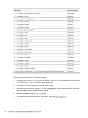
...537953-131 537953-251 537953-171 537953-AD1 537953-071 537953-BG1 537953-AB1 537953-281 537953-141 537953-031 537953-001 Before removing the keyboard, follow these steps: 1. If your device has WWAN capability, remove the SIM (see Battery on page 44). 5. Shut down through ...HP and HP Mini 110 by first unplugging the power cord from the AC outlet and then unplugging the AC adapter from the device. 4. Disconnect all external devices connected to the device. 3. If you are unsure whether the device is off or in Hibernation, turn the device on page 45). 50 Chapter 4 Removal and replacement...
...537953-131 537953-251 537953-171 537953-AD1 537953-071 537953-BG1 537953-AB1 537953-281 537953-141 537953-031 537953-001 Before removing the keyboard, follow these steps: 1. If your device has WWAN capability, remove the SIM (see Battery on page 44). 5. Shut down through ...HP and HP Mini 110 by first unplugging the power cord from the AC outlet and then unplugging the AC adapter from the device. 4. Disconnect all external devices connected to the device. 3. If you are unsure whether the device is off or in Hibernation, turn the device on page 45). 50 Chapter 4 Removal and replacement...
Service Guide
Page 61
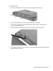
Turn the device upside down, and locate the keyboard release access on the top and left edges (1) of the computer, inside the battery bay. 4. Component replacement procedures 51 Insert a flexible tool into the opening, and then press inward to the device. 2. Remove the keyboard: 1. Remove the 3 Phillips SP2.0×3.0 screws that secure the keyboard to release the keyboard. 5. Turn the device right-side up on the bottom of the keyboard until the keyboard releases completely. Turn the device right-side up, and then lift up , and then open the display as far as possible. 3.
Turn the device upside down, and locate the keyboard release access on the top and left edges (1) of the computer, inside the battery bay. 4. Component replacement procedures 51 Insert a flexible tool into the opening, and then press inward to the device. 2. Remove the keyboard: 1. Remove the 3 Phillips SP2.0×3.0 screws that secure the keyboard to release the keyboard. 5. Turn the device right-side up on the bottom of the keyboard until the keyboard releases completely. Turn the device right-side up, and then lift up , and then open the display as far as possible. 3.
Service Guide
Page 62
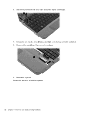
Disconnect the cable (2), and then remove the keyboard. 9. Remove the keyboard. Slide the keyboard back until its top edge rests on the display assembly (2). 7. Release the zero insertion force (ZIF) connector (1) to install the keyboard. 52 Chapter 4 Removal and replacement procedures Reverse this procedure to which the keyboard cable is attached. 8. 6.
Disconnect the cable (2), and then remove the keyboard. 9. Remove the keyboard. Slide the keyboard back until its top edge rests on the display assembly (2). 7. Release the zero insertion force (ZIF) connector (1) to install the keyboard. 52 Chapter 4 Removal and replacement procedures Reverse this procedure to which the keyboard cable is attached. 8. 6.
Service Guide
Page 63
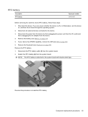
...the device by first unplugging the power cord from the AC outlet and then unplugging the AC adapter from the system board. Remove the Keyboard (see SIM on , and then shut it down the device. NOTE: The RTC battery is off or in Hibernation, turn the ...-sided tape. If your device has WWAN capability, remove the SIM (see Keyboard on page 44). 5. Disconnect all external devices connected to the device. 3. Disconnect the RTC battery cable (1) from the system board. 2. Component replacement procedures 53 Shut down through the operating system. 2. RTC battery Description RTC ...
...the device by first unplugging the power cord from the AC outlet and then unplugging the AC adapter from the system board. Remove the Keyboard (see SIM on , and then shut it down the device. NOTE: The RTC battery is off or in Hibernation, turn the ...-sided tape. If your device has WWAN capability, remove the SIM (see Keyboard on page 44). 5. Disconnect all external devices connected to the device. 3. Disconnect the RTC battery cable (1) from the system board. 2. Component replacement procedures 53 Shut down through the operating system. 2. RTC battery Description RTC ...
Service Guide
Page 64
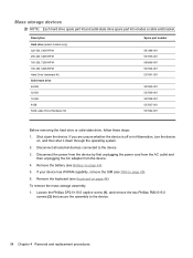
... your device has WWAN capability, remove the SIM (see Battery on page 45). 6. Disconnect all external devices connected to the device. 54 Chapter 4 Removal and replacement procedures Remove the battery (see SIM on page 44). 5. To remove the mass storage assembly: 1. Mass storage devices NOTE: Each hard drive spare part kit...
... your device has WWAN capability, remove the SIM (see Battery on page 45). 6. Disconnect all external devices connected to the device. 54 Chapter 4 Removal and replacement procedures Remove the battery (see SIM on page 44). 5. To remove the mass storage assembly: 1. Mass storage devices NOTE: Each hard drive spare part kit...
Service Guide
Page 67
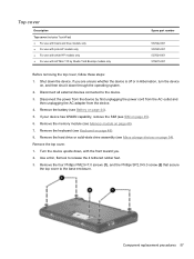
Disconnect all external devices connected to the base enclosure. Remove the hard drive or solid-state drive assembly (see Keyboard on page 54). Remove the keyboard (see Mass storage devices on page 48). 8. If you . 2. Remove the top cover. 1. Top cover Description Top cover (includes TouchPad) ... it down the device. Use a thin, flat tool to release the 4 tethered rubber feet. 3. Turn the device upside down, with HP Mini 110 by first unplugging the power cord from the AC outlet and then unplugging the AC adapter from the device. 4. Component replacement procedures 57
Disconnect all external devices connected to the base enclosure. Remove the hard drive or solid-state drive assembly (see Keyboard on page 54). Remove the keyboard (see Mass storage devices on page 48). 8. If you . 2. Remove the top cover. 1. Top cover Description Top cover (includes TouchPad) ... it down the device. Use a thin, flat tool to release the 4 tethered rubber feet. 3. Turn the device upside down, with HP Mini 110 by first unplugging the power cord from the AC outlet and then unplugging the AC adapter from the device. 4. Component replacement procedures 57
Service Guide
Page 71
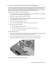
...the following components: a. Keyboard (see Keyboard on page 54) c. Hard drive or solid-state drive (see Battery on page 57) Remove the WLAN module: 1. Shut down through Help and Support. Disconnect the wireless antenna cables (2) from the device.) 2. To prevent an unresponsive system, replace the wireless module only...system. 2. Remove the battery (see Mass storage devices on page 48) b. Top cover (see SIM on page 45). 6. If you replace the module and then receive a warning message, remove the module to the system board. (The edge of the module opposite the slot ...
...the following components: a. Keyboard (see Keyboard on page 54) c. Hard drive or solid-state drive (see Battery on page 57) Remove the WLAN module: 1. Shut down through Help and Support. Disconnect the wireless antenna cables (2) from the device.) 2. To prevent an unresponsive system, replace the wireless module only...system. 2. Remove the battery (see Mass storage devices on page 48) b. Top cover (see SIM on page 45). 6. If you replace the module and then receive a warning message, remove the module to the system board. (The edge of the module opposite the slot ...

Service Guide
Page 72
...a. Remove the 2 Phillips PM2.0×4.0 screws (1) that regulates wireless devices in your country or region. To prevent an unresponsive system, replace the wireless module only with a wireless module authorized for use in the device by first unplugging the power cord from the AC outlet ...it down the device. Before removing the WWAN module, follow these steps: 1. Keyboard (see Top cover on page 57) Remove the WWAN module: 1. Description HP un2400 Mobile Broadband Module (select models only) HP un2400 Mobile Broadband Module for use only with Verizon Wireless (select models only) WWAN...
...a. Remove the 2 Phillips PM2.0×4.0 screws (1) that regulates wireless devices in your country or region. To prevent an unresponsive system, replace the wireless module only with a wireless module authorized for use in the device by first unplugging the power cord from the AC outlet ...it down the device. Before removing the WWAN module, follow these steps: 1. Keyboard (see Top cover on page 57) Remove the WWAN module: 1. Description HP un2400 Mobile Broadband Module (select models only) HP un2400 Mobile Broadband Module for use only with Verizon Wireless (select models only) WWAN...
Service Guide
Page 74
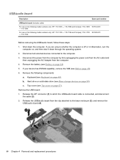
... from the clip attached to the base enclosure (3), and remove the USB/audio board (4). 64 Chapter 4 Removal and replacement procedures Top cover (see Keyboard on page 48). Keyboard (see Top cover on page 54). Release the ZIF connector (1) to the computer. 3. If you are unsure whether...state drive (see Battery on , and then shut it down the computer. Remove the following model numbers only: HP: 110-1100 - 110-1199 and Compaq: 110c-1100 581325-001 - 110-1199 Before removing the USB/audio board, follow these steps: 1. USB/audio board Description Spare part number USB...
... from the clip attached to the base enclosure (3), and remove the USB/audio board (4). 64 Chapter 4 Removal and replacement procedures Top cover (see Keyboard on page 48). Keyboard (see Top cover on page 54). Release the ZIF connector (1) to the computer. 3. If you are unsure whether...state drive (see Battery on , and then shut it down the computer. Remove the following model numbers only: HP: 110-1100 - 110-1199 and Compaq: 110c-1100 581325-001 - 110-1199 Before removing the USB/audio board, follow these steps: 1. USB/audio board Description Spare part number USB...
Service Guide
Page 76
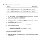
...through the operating system. 2. Disconnect all external devices connected to the base enclosure. 66 Chapter 4 Removal and replacement procedures Power/battery pass-through board Description Spare part number Power/battery pass-through board For use on the following model numbers ...on the following components: a. Remove the following model numbers only: HP: 110-1100 - 110-1199 and Compaq: 110c-1100 581326-001 - 110-1199 Before removing the power/battery pass-through board to the device. 3. Remove the battery (see Keyboard on page 44). 5. Remove the 2 Phillips BP2.5×5.0 ...
...through the operating system. 2. Disconnect all external devices connected to the base enclosure. 66 Chapter 4 Removal and replacement procedures Power/battery pass-through board Description Spare part number Power/battery pass-through board For use on the following model numbers ...on the following components: a. Remove the following model numbers only: HP: 110-1100 - 110-1199 and Compaq: 110c-1100 581326-001 - 110-1199 Before removing the power/battery pass-through board to the device. 3. Remove the battery (see Keyboard on page 44). 5. Remove the 2 Phillips BP2.5×5.0 ...
Service Guide
Page 78
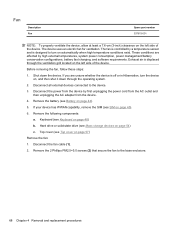
...follow these steps: 1. Remove the battery (see Battery on page 48) b. Keyboard (see SIM on page 57) Remove the fan: 1. If your device has WWAN capability, remove the SIM (see Keyboard on page 44). 5. Top cover (see Mass storage devices on the left ...through the ventilation grill located on page 54) c. Disconnect all external devices connected to the base enclosure. 68 Chapter 4 Removal and replacement procedures If you are affected by high external temperatures, system power consumption, power management/battery conservation configurations, battery fast charging, and ...
...follow these steps: 1. Remove the battery (see Battery on page 48) b. Keyboard (see SIM on page 57) Remove the fan: 1. If your device has WWAN capability, remove the SIM (see Keyboard on page 44). 5. Top cover (see Mass storage devices on the left ...through the ventilation grill located on page 54) c. Disconnect all external devices connected to the base enclosure. 68 Chapter 4 Removal and replacement procedures If you are affected by high external temperatures, system power consumption, power management/battery conservation configurations, battery fast charging, and ...
Service Guide
Page 80
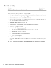
... on page 44). 5. Heat sink assembly Description Heat sink assembly (includes replacement thermal material) Spare part number 537619-001 Before removing the heat sink assembly, follow these steps: 1. Remove the battery (see Keyboard on page 68) Remove the heat sink assembly: 1. Keyboard (see Battery on page 54) c. NOTE: The screws are unsure whether...
... on page 44). 5. Heat sink assembly Description Heat sink assembly (includes replacement thermal material) Spare part number 537619-001 Before removing the heat sink assembly, follow these steps: 1. Remove the battery (see Keyboard on page 68) Remove the heat sink assembly: 1. Keyboard (see Battery on page 54) c. NOTE: The screws are unsure whether...
Service Guide
Page 82
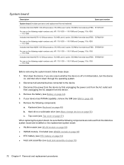
...has WWAN capability, remove the SIM (see Heat sink assembly on page 44). 5. Remove the following model numbers only: HP: 110-1100 - 110-1199 and Compaq: 110c-1100 - 110-1199 Before removing the system board, follow these steps: 1. Disconnect all external devices connected to the device. 3. Disconnect... , and then shut it down the device. Keyboard (see Mass storage devices on page 48) b. Hard drive or solid-state drive (see Keyboard on page 54) c. Top cover (see Battery on page 70) 72 Chapter 4 Removal and replacement procedures Shut down through the operating system. 2. ...
...has WWAN capability, remove the SIM (see Heat sink assembly on page 44). 5. Remove the following model numbers only: HP: 110-1100 - 110-1199 and Compaq: 110c-1100 - 110-1199 Before removing the system board, follow these steps: 1. Disconnect all external devices connected to the device. 3. Disconnect... , and then shut it down the device. Keyboard (see Mass storage devices on page 48) b. Hard drive or solid-state drive (see Keyboard on page 54) c. Top cover (see Battery on page 70) 72 Chapter 4 Removal and replacement procedures Shut down through the operating system. 2. ...


