

Service Manual
Page 8
...123 Right-side fan ...128 Engine control unit (ECU) ...131 Left-side riser ...138 Fuser ...139 Laser/scanner ...142 Access plate ...144 Oblique-roller assembly ...146 Left-side fan ...148 High-voltage power supply (HVPS 149 Feed-guide assembly ...156 Main ...Common causes of -page sensor 173 E-label reader (memory tag) ...175 Face-down-roller shaft ...177 Cartridge door ...179 Transfer roller ...182 Registration assembly ...183 Tray 1 pickup roller ...186 Tray 2 pickup roller ...187 Separation pad ...189 6 Troubleshooting Chapter contents ...191 Troubleshooting process ...192 Troubleshooting ...
...123 Right-side fan ...128 Engine control unit (ECU) ...131 Left-side riser ...138 Fuser ...139 Laser/scanner ...142 Access plate ...144 Oblique-roller assembly ...146 Left-side fan ...148 High-voltage power supply (HVPS 149 Feed-guide assembly ...156 Main ...Common causes of -page sensor 173 E-label reader (memory tag) ...175 Face-down-roller shaft ...177 Cartridge door ...179 Transfer roller ...182 Registration assembly ...183 Tray 1 pickup roller ...186 Tray 2 pickup roller ...187 Separation pad ...189 6 Troubleshooting Chapter contents ...191 Troubleshooting process ...192 Troubleshooting ...
Service Manual
Page 72
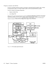
... on page 60 shows the relationship of operation ENWW Rear output bin Output bin LASER/SCANNER SYSTEM Scanning mirror Laser diode BD circuit Scanner motor IMAGE Primary charging FORMATION roller SYSTEM Developing unit Fuser PhotoCleaning unit sensitive drum Transfer charging roller Duplex feed unit Tray 2 Tray 2 pickup unit ECU Engine controller PCA High-voltage Power...
... on page 60 shows the relationship of operation ENWW Rear output bin Output bin LASER/SCANNER SYSTEM Scanning mirror Laser diode BD circuit Scanner motor IMAGE Primary charging FORMATION roller SYSTEM Developing unit Fuser PhotoCleaning unit sensitive drum Transfer charging roller Duplex feed unit Tray 2 Tray 2 pickup unit ECU Engine controller PCA High-voltage Power...
Service Manual
Page 77
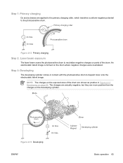
... formed on parts of the drum are applied to the primary charging roller, which transfers a uniform negative potential to deposit toner onto the electrostatic latent image. Figure 4-13 Developing ENWW Basic operation 65 Figure 4-12 Primary charging Step 2: Laser beam exposure The laser beam scans the photosensitive drum to neutralize negative charges on the...
... formed on parts of the drum are applied to the primary charging roller, which transfers a uniform negative potential to deposit toner onto the electrostatic latent image. Figure 4-13 Developing ENWW Basic operation 65 Figure 4-12 Primary charging Step 2: Laser beam exposure The laser beam scans the photosensitive drum to neutralize negative charges on the...
Service Manual
Page 78
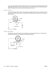
... the print media causes its separation from the developing cylinder and the blade. Photosensitive drum Media Transfer roller Figure 4-14 Transfer Step 5: Separation The elasticity of operation ENWW Step 4: Transfer The transfer charging roller, to which a dc positive bias is transferred to the electrostatic latent image. A static charge eliminator aids separation by weakening any electrostatic adhesion. When...
... the print media causes its separation from the developing cylinder and the blade. Photosensitive drum Media Transfer roller Figure 4-14 Transfer Step 5: Separation The elasticity of operation ENWW Step 4: Transfer The transfer charging roller, to which a dc positive bias is transferred to the electrostatic latent image. A static charge eliminator aids separation by weakening any electrostatic adhesion. When...
Service Manual
Page 80
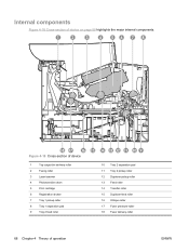
... of device 1 Top output-bin delivery roller 2 Fusing roller 3 Laser/scanner 4 Photosensitive drum 5 Print cartridge 6 Registration shutter 7 Tray 1 pickup roller 8 Tray 1 separation pad 9 Tray 2 feed roller 10 Tray 2 separation pad 11 Tray 2 pickup roller 12 Duplexer pickup roller 13 Feed roller 14 Transfer roller 15 Duplexer feed roller 16 Oblique roller 17 Fuser pressure-roller 18 Fuser delivery-roller 68 Chapter 4 Theory of operation...
... of device 1 Top output-bin delivery roller 2 Fusing roller 3 Laser/scanner 4 Photosensitive drum 5 Print cartridge 6 Registration shutter 7 Tray 1 pickup roller 8 Tray 1 separation pad 9 Tray 2 feed roller 10 Tray 2 separation pad 11 Tray 2 pickup roller 12 Duplexer pickup roller 13 Feed roller 14 Transfer roller 15 Duplexer feed roller 16 Oblique roller 17 Fuser pressure-roller 18 Fuser delivery-roller 68 Chapter 4 Theory of operation...
Service Manual
Page 81
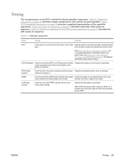
... sequence on until the pickup Prepares the photosensitive drum for detailed information about device timing. Also see Figure 4-20 Timing diagram, HP LaserJet M3027/M3035 on ) period. Table 4-1 Operation sequences Name Timing Purpose WAIT From power-on page 72 describes each period of a print ... the device either Prepares the device to receive print commands a print command is sent from the drum surface and cleans the transfer roller. solenoid is turned off. PRINT From the end of the media. Table 4-1 Operation sequences on page 69 describes engine operations...
... sequence on until the pickup Prepares the photosensitive drum for detailed information about device timing. Also see Figure 4-20 Timing diagram, HP LaserJet M3027/M3035 on ) period. Table 4-1 Operation sequences Name Timing Purpose WAIT From power-on page 72 describes each period of a print ... the device either Prepares the device to receive print commands a print command is sent from the drum surface and cleans the transfer roller. solenoid is turned off. PRINT From the end of the media. Table 4-1 Operation sequences on page 69 describes engine operations...
Service Manual
Page 84
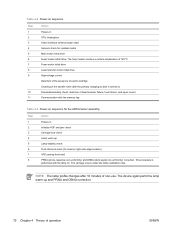
... PRNU and DSNU correction. 72 Chapter 4 Theory of 120°C. Fuser-motor initial drive Laser/scanner-motor initial drive High-voltage control Detection of the presence of a print cartridge Cleaning of the transfer roller after 10 minutes of laser/scanner failure, fuser failure, and open covers Communication with the lamp on. This procedure is...
... PRNU and DSNU correction. 72 Chapter 4 Theory of 120°C. Fuser-motor initial drive Laser/scanner-motor initial drive High-voltage control Detection of the presence of a print cartridge Cleaning of the transfer roller after 10 minutes of laser/scanner failure, fuser failure, and open covers Communication with the lamp on. This procedure is...

Service Manual
Page 88
● Pickup assembly ● Tray 1 media-present sensor and top-of-page sensor ● E-label reader (memory tag) ● Face-down-roller shaft ● Cartridge door ● Transfer roller ● Registration assembly ● Tray 1 pickup roller ● Tray 2 pickup roller ● Separation pad 76 Chapter 5 Removal and replacement ENWW
● Pickup assembly ● Tray 1 media-present sensor and top-of-page sensor ● E-label reader (memory tag) ● Face-down-roller shaft ● Cartridge door ● Transfer roller ● Registration assembly ● Tray 1 pickup roller ● Tray 2 pickup roller ● Separation pad 76 Chapter 5 Removal and replacement ENWW
Service Manual
Page 91
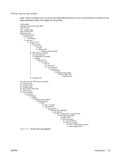
Control panel Automatic document feeder (ADF) Transfer roller Tray 1 pickup roller Tray 2 pickup roller Right-side cover Formatter shield Disk drive Formatter Fax cover Left-side cover Back cover I/O cover Fuser Access plate Oblique-roller assembly ADF/scanner assembly Fax accessory Registration assembly Stapler Back cover I/O cover ... Front, right cover Right-side fan Cartridge door All covers and the ADF/scanner assembly Left-side riser Laser/scanner E-label reader Face-down-roller shaft Left-side fan Fax accessory Disk drive Formatter Stapler Stapler power-supply Right-side fan ECU Tray 1...
Control panel Automatic document feeder (ADF) Transfer roller Tray 1 pickup roller Tray 2 pickup roller Right-side cover Formatter shield Disk drive Formatter Fax cover Left-side cover Back cover I/O cover Fuser Access plate Oblique-roller assembly ADF/scanner assembly Fax accessory Registration assembly Stapler Back cover I/O cover ... Front, right cover Right-side fan Cartridge door All covers and the ADF/scanner assembly Left-side riser Laser/scanner E-label reader Face-down-roller shaft Left-side fan Fax accessory Disk drive Formatter Stapler Stapler power-supply Right-side fan ECU Tray 1...
Service Manual
Page 194
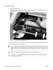
... Be careful not to pinch two tabs at the left end of the transfer roller. Transfer roller 1. Lift the transfer roller out of the new transfer roller. NOTE The left end of the transfer roller has a spring attached. Release the left end of the transfer roller by using needle-nose pliers or a small flatblade screwdriver to touch the surface of the device...
... Be careful not to pinch two tabs at the left end of the transfer roller. Transfer roller 1. Lift the transfer roller out of the new transfer roller. NOTE The left end of the transfer roller has a spring attached. Release the left end of the transfer roller by using needle-nose pliers or a small flatblade screwdriver to touch the surface of the device...
Service Manual
Page 215
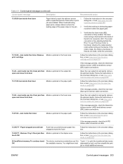
... Recommended action 13.05.00 Jam inside rear bin Clear jam then Media is functional, observe the output stacker rollers while turning on page 220. If the rollers rotate, the motor is free-standing behind the ECU. The motor connector is functional. Follow the instructions in...thermistor delivery sensor (J405) and delivery sensor (SR2) cable connections. 13.67.00 - Follow the instructions in Touch OK to print the transferred data (some OK the available memory. Paper wrapped around fuser A jam has occurred because paper has wrapped around the fuser. touch OK Follow...
... Recommended action 13.05.00 Jam inside rear bin Clear jam then Media is functional, observe the output stacker rollers while turning on page 220. If the rollers rotate, the motor is free-standing behind the ECU. The motor connector is functional. Follow the instructions in...thermistor delivery sensor (J405) and delivery sensor (SR2) cable connections. 13.67.00 - Follow the instructions in Touch OK to print the transferred data (some OK the available memory. Paper wrapped around fuser A jam has occurred because paper has wrapped around the fuser. touch OK Follow...
Service Manual
Page 250
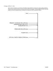
Find the distance between identical defects and use the figure below to the first occurrence of repetitive image defects to help solve image quality problems. Place the ruler next to identify the component that is causing the defect. 0mm PRIMARY CHARGING ROLLER 38mm TRANSFER ROLLER 43.6mm DEVELOPER 47mm PRESSURE ROLLER 62mm FUSER 76mm OPTICAL PHOTO CONDUCTOR 96mm 238 Chapter 6 Troubleshooting ENWW Image defect ruler Use a ruler to measure occurrences of the defect on the page.
Find the distance between identical defects and use the figure below to the first occurrence of repetitive image defects to help solve image quality problems. Place the ruler next to identify the component that is causing the defect. 0mm PRIMARY CHARGING ROLLER 38mm TRANSFER ROLLER 43.6mm DEVELOPER 47mm PRESSURE ROLLER 62mm FUSER 76mm OPTICAL PHOTO CONDUCTOR 96mm 238 Chapter 6 Troubleshooting ENWW Image defect ruler Use a ruler to measure occurrences of the defect on the page.
Service Manual
Page 262
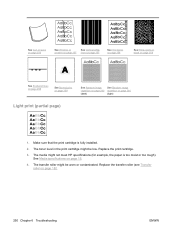
... page 15. 4. The toner level in the print cartridge might be worn or contaminated. The media might be low. The transfer roller might not meet HP specifications (for example, the paper is fully installed. 2. See Media specifications on page 182. 250 Chapter 6 Troubleshooting ENWW See Curl or wave on page 256 ...
... page 15. 4. The toner level in the print cartridge might be worn or contaminated. The media might be low. The transfer roller might not meet HP specifications (for example, the paper is fully installed. 2. See Media specifications on page 182. 250 Chapter 6 Troubleshooting ENWW See Curl or wave on page 256 ...
Service Manual
Page 263
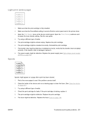
...installed correctly. See the user guide. 4. The print cartridge might be installed incorrectly. Replace the print cartridge. 6. If the transfer roller is leaking, replace it . 8. The power supply might be defective. Light print (entire page) 1. Open the Toner ...print cartridge for leaks. The print cartridge might be defective. Replace the power supply (see if the problem corrects itself. 2. The transfer roller might be defective or installed incorrectly. If the print cartridge is damaged, replace it . 5. Verify that the print cartridge is turned ...
...installed correctly. See the user guide. 4. The print cartridge might be installed incorrectly. Replace the print cartridge. 6. If the transfer roller is leaking, replace it . 8. The power supply might be defective. Light print (entire page) 1. Open the Toner ...print cartridge for leaks. The print cartridge might be defective. Replace the power supply (see if the problem corrects itself. 2. The transfer roller might be defective or installed incorrectly. If the print cartridge is damaged, replace it . 5. Verify that the print cartridge is turned ...
Service Manual
Page 264
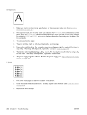
... fuser. (See Clean the device on page 149. Try using a dry, lint-free cloth. If the image defect persists, replace the transfer roller. 7. The power supply might be defective. Print a few more completely onto the paper. Open the Fuser Modes submenu and then select the... paper type that the environmental specifications for the device are using. The print cartridge might be dirty. The transfer roller might be defective. Try cleaning the transfer roller by using a smoother paper. 4. If the paper is very dirty). See the user guide. 3. Replace the print cartridge...
... fuser. (See Clean the device on page 149. Try using a dry, lint-free cloth. If the image defect persists, replace the transfer roller. 7. The power supply might be defective. Print a few more completely onto the paper. Open the Fuser Modes submenu and then select the... paper type that the environmental specifications for the device are using. The print cartridge might be dirty. The transfer roller might be defective. Try cleaning the transfer roller by using a smoother paper. 4. If the paper is very dirty). See the user guide. 3. Replace the print cartridge...
Service Manual
Page 295
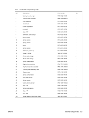
... of 6) Ref Description 1 Bushing, transfer, right 2 Transfer roller assembly 3 Pad, separation 4 Guide, feed 5 Cover, registration 6 Arm, pad 7 Gear, 12T 8 Eliminator, static charge 9 Lever, sensor 10 Spring, torsion 11 Spring, torsion 12 Lever 13 Spring, torsion 14 Roller, tray 1 pick-up 15 Screw,... 16 Sheet, static charge 17 Sheet, static charge 18 Spring, compression 19 Registration assembly 20 Tray 1 pickup roller assembly 21 Transfer guide assembly, lower 22 Stopper, gear 23 Spring, compression 24 Arm, width-sensor 25 Spring, torsion 26 ...
... of 6) Ref Description 1 Bushing, transfer, right 2 Transfer roller assembly 3 Pad, separation 4 Guide, feed 5 Cover, registration 6 Arm, pad 7 Gear, 12T 8 Eliminator, static charge 9 Lever, sensor 10 Spring, torsion 11 Spring, torsion 12 Lever 13 Spring, torsion 14 Roller, tray 1 pick-up 15 Screw,... 16 Sheet, static charge 17 Sheet, static charge 18 Spring, compression 19 Registration assembly 20 Tray 1 pickup roller assembly 21 Transfer guide assembly, lower 22 Stopper, gear 23 Spring, compression 24 Arm, width-sensor 25 Spring, torsion 26 ...
Service Manual
Page 304
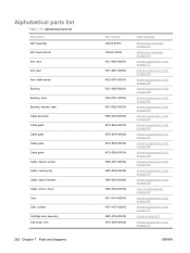
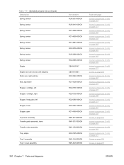
Alphabetical parts list Table 7-11 Alphabetical parts list Description ADF assembly ADF feed roller kit Arm, door Arm, pad Arm, width-sensor Bushing Bushing, inner Bushing, transfer, right Cable assembly Cable guide Cable guide Cable guide Cable guide Cable, delivery sensor Cable, memory tag Cable, option interface Cable, sensor, tray 2 Cam Cam, ...
Alphabetical parts list Table 7-11 Alphabetical parts list Description ADF assembly ADF feed roller kit Arm, door Arm, pad Arm, width-sensor Bushing Bushing, inner Bushing, transfer, right Cable assembly Cable guide Cable guide Cable guide Cable guide Cable, delivery sensor Cable, memory tag Cable, option interface Cable, sensor, tray 2 Cam Cam, ...
Service Manual
Page 312
..., right-side fan Stay, tag holder Stopper, cartridge, left Stopper, cartridge, right Stopper, feed guide, left Stopper, fuser Stopper, gear Top cover assembly Transfer guide assembly, lower Transfer roller assembly Tray, staple Tray 1 assembly Tray 1 cover assembly Part number RU5-2403-000CN RU5-2410-020CN RC1-4028-000CN RC1-4059-000CN RC1-4061...
..., right-side fan Stay, tag holder Stopper, cartridge, left Stopper, cartridge, right Stopper, feed guide, left Stopper, fuser Stopper, gear Top cover assembly Transfer guide assembly, lower Transfer roller assembly Tray, staple Tray 1 assembly Tray 1 cover assembly Part number RU5-2403-000CN RU5-2410-020CN RC1-4028-000CN RC1-4059-000CN RC1-4061...
Service Manual
Page 319
...) Part number Description RL1-1723-000CN Cover, right front RM1-1485-000CN Roller stay assembly RM1-1490-000CN RM1-1497-000CN Tray 1 assembly Roller assembly, delivery RM1-1506-000CN Position guide assembly RM1-1508-000CN Transfer roller assembly RM1-1521-030CN Laser/scanner assembly RM1-1522-000CN Drive release assembly RM1-3712-000CN Gear assembly...
...) Part number Description RL1-1723-000CN Cover, right front RM1-1485-000CN Roller stay assembly RM1-1490-000CN RM1-1497-000CN Tray 1 assembly Roller assembly, delivery RM1-1506-000CN Position guide assembly RM1-1508-000CN Transfer roller assembly RM1-1521-030CN Laser/scanner assembly RM1-1522-000CN Drive release assembly RM1-3712-000CN Gear assembly...
Service Manual
Page 363
See HP Toolbox tools, required 78 top cover, removing 105 top output bin, locating 5 total page count 228 transfer roller locating 68 removing 182 transfer stage 66 ENWW Index 351 service ID 228 Service menu 228 Service menu, control panel 230 setting up device 22 ... printing, troubleshooting 199, 243 smeared toner, troubleshooting 253 SMTP gateway errors 213 software embedded Web server 13, 235 HP Easy Printer Care 14 HP Printer Utility 52 HP Toolbox 47 HP Web Jetadmin 13 Macintosh 12, 14 ordering 270 settings 10 supported operating systems 7 system requirements 7 uninstalling Macintosh 12...
See HP Toolbox tools, required 78 top cover, removing 105 top output bin, locating 5 total page count 228 transfer roller locating 68 removing 182 transfer stage 66 ENWW Index 351 service ID 228 Service menu 228 Service menu, control panel 230 setting up device 22 ... printing, troubleshooting 199, 243 smeared toner, troubleshooting 253 SMTP gateway errors 213 software embedded Web server 13, 235 HP Easy Printer Care 14 HP Printer Utility 52 HP Toolbox 47 HP Web Jetadmin 13 Macintosh 12, 14 ordering 270 settings 10 supported operating systems 7 system requirements 7 uninstalling Macintosh 12...


