
User Manual
Page 5
... Example Network Topologies 2-14 As a Desktop Switch 2-14 As a Segment Switch 2-15 Connecting to a Power Source 2-12 6. Contents 1 Introducing the HP Procurve Switch 2124 Front of the Switch 1-2 Network Ports 1-2 Reset Button 1-2 LEDs 1-3 LED Mode Select Button and Indicator LEDs 1-4 Back of the Switch 1-5 Power Connector 1-5 Features 1-6 Switch Operation Overview 1-6 Address Table...
... Example Network Topologies 2-14 As a Desktop Switch 2-14 As a Segment Switch 2-15 Connecting to a Power Source 2-12 6. Contents 1 Introducing the HP Procurve Switch 2124 Front of the Switch 1-2 Network Ports 1-2 Reset Button 1-2 LEDs 1-3 LED Mode Select Button and Indicator LEDs 1-4 Back of the Switch 1-5 Power Connector 1-5 Features 1-6 Switch Operation Overview 1-6 Address Table...

User Manual
Page 6
3 Troubleshooting Basic Troubleshooting Tips 3-1 Diagnosing with the LEDs 3-3 Hardware Diagnostic Tests 3-5 Testing the Switch by Resetting It 3-5 Testing Twisted-Pair Cabling 3-5 Testing End-to-End Network Communications 3-6 HP Customer Support Services 3-6 A Specifications Physical A-1 Electrical A-1 Environmental A-1 Acoustic A-1 Connectors A-2 Safety A-2 B Switch Ports and Network Cables Switch Ports B-1 Cables B-2 Twisted-Pair Cable/Connector Pin-Outs B-2 Straight...
3 Troubleshooting Basic Troubleshooting Tips 3-1 Diagnosing with the LEDs 3-3 Hardware Diagnostic Tests 3-5 Testing the Switch by Resetting It 3-5 Testing Twisted-Pair Cabling 3-5 Testing End-to-End Network Communications 3-6 HP Customer Support Services 3-6 A Specifications Physical A-1 Electrical A-1 Environmental A-1 Acoustic A-1 Connectors A-2 Safety A-2 B Switch Ports and Network Cables Switch Ports B-1 Cables B-2 Twisted-Pair Cable/Connector Pin-Outs B-2 Straight...
User Manual
Page 8
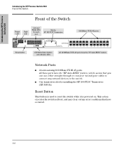
...you can use either straight-through or crossover twisted-pair cables to connect any network devices to reset the switch while it is used to the switch. Introducing the HP Procurve Switch 2124 Introducing the HP Procurve Switch 2124 Front of the Switch Front of the Switch Link and Mode LEDs Slot for... Power Fault for installing the HP 100-FX SC Transceiver (HP J4853A) Reset Button This button is powered on. I One transceiver slot for each HP 100-FX SC Transceiver LED LED port 10/100Base-TX RJ-45 ports...
...you can use either straight-through or crossover twisted-pair cables to connect any network devices to reset the switch while it is used to the switch. Introducing the HP Procurve Switch 2124 Introducing the HP Procurve Switch 2124 Front of the Switch Front of the Switch Link and Mode LEDs Slot for... Power Fault for installing the HP 100-FX SC Transceiver (HP J4853A) Reset Button This button is powered on. I One transceiver slot for each HP 100-FX SC Transceiver LED LED port 10/100Base-TX RJ-45 ports...
User Manual
Page 9
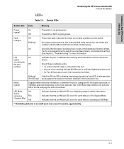
... (orange) Off Blinking* The normal state; On On briefly after the switch is configured for more information. Introducing the HP Procurve Switch 2124 Introducing the HP Procurve Switch 2124 Front of switch self test. Link On (green - Under this condition, the Port 25 Link LED ... activity information. An unsupported transceiver has been installed in Full Duplex Mode. See "LED Mode Select Button and Indicator LEDs" on or reset, at 100 Mbps. * The blinking behavior is enabled and receiving a link indication from the connected device. Indicates that the port Mode...
... (orange) Off Blinking* The normal state; On On briefly after the switch is configured for more information. Introducing the HP Procurve Switch 2124 Introducing the HP Procurve Switch 2124 Front of switch self test. Link On (green - Under this condition, the Port 25 Link LED ... activity information. An unsupported transceiver has been installed in Full Duplex Mode. See "LED Mode Select Button and Indicator LEDs" on or reset, at 100 Mbps. * The blinking behavior is enabled and receiving a link indication from the connected device. Indicates that the port Mode...
User Manual
Page 35
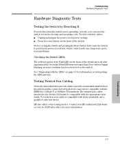
... LAN dealer or your cable is not operating correctly, you can reset the switch to the Switch 2124 must be compatible with the IEEE 802.3 10Base-T or 100Base-TX standards. HP also offers a wire testing service. If this LED stays on longer than 10 seconds or begins blinking, an...Diagnosing with the LEDs" on page 3-3 for more information. 3-5 Troubleshooting To verify that your local HP sales office for information on the front of the switch Power cycling the switch and pressing the Reset button both cause the switch to provide a link or provide an unreliable link between the switch ...
... LAN dealer or your cable is not operating correctly, you can reset the switch to the Switch 2124 must be compatible with the IEEE 802.3 10Base-T or 100Base-TX standards. HP also offers a wire testing service. If this LED stays on longer than 10 seconds or begins blinking, an...Diagnosing with the LEDs" on page 3-3 for more information. 3-5 Troubleshooting To verify that your local HP sales office for information on the front of the switch Power cycling the switch and pressing the Reset button both cause the switch to provide a link or provide an unreliable link between the switch ...

User Manual
Page 55
... 1-6 filtering out traffic ... 1-7 flooding traffic ... 1-7 forwarding traffic ... 1-7 moves and changes ... 1-7 operation ... 1-6 Auto-MDIX see HP Auto-MDIX B back of switch description ... 1-5 power connector ... 1-5 backbone switch topology with ... 2-16 basic troubleshooting tips ... 3-1 blinking... LEDs error indications ... 3-3 buttons LED Mode Select button ... 1-4 Reset button ... 1-2 C cabinet mounting the switch in ... 2-8 cables 100Base-FX connections ... 2-4 100Base-TX connections ... 2-4 10Base-T connections...
... 1-6 filtering out traffic ... 1-7 flooding traffic ... 1-7 forwarding traffic ... 1-7 moves and changes ... 1-7 operation ... 1-6 Auto-MDIX see HP Auto-MDIX B back of switch description ... 1-5 power connector ... 1-5 backbone switch topology with ... 2-16 basic troubleshooting tips ... 3-1 blinking... LEDs error indications ... 3-3 buttons LED Mode Select button ... 1-4 Reset button ... 1-2 C cabinet mounting the switch in ... 2-8 cables 100Base-FX connections ... 2-4 100Base-TX connections ... 2-4 10Base-T connections...

User Manual
Page 56
... traffic ... 1-7 forwarding traffic ... 1-7 front of switch 10/100Base-TX ports ... 1-2 description ... 1-2 LED Mode Select button and LEDs ... 1-4 network ports ... 1-2 Reset button ... 1-2 slot for transceiver module ... 1-2 H horizontal surface, mounting switch on ... 2-12 HP Auto-MDIX description ... 1-6 effect on cable usage ... 2-4, 2-14-2-15, B-2 I included parts ... 2-1 installation connecting the switch to a power source ... 2-12 mounting...
... traffic ... 1-7 forwarding traffic ... 1-7 front of switch 10/100Base-TX ports ... 1-2 description ... 1-2 LED Mode Select button and LEDs ... 1-4 network ports ... 1-2 Reset button ... 1-2 slot for transceiver module ... 1-2 H horizontal surface, mounting switch on ... 2-12 HP Auto-MDIX description ... 1-6 effect on cable usage ... 2-4, 2-14-2-15, B-2 I included parts ... 2-1 installation connecting the switch to a power source ... 2-12 mounting...

User Manual
Page 57
... connecting the switch to a power source ... 2-12 description ... 1-1 electrical specifications ... A-1 physical ... A-1 environmental specifications ... C-8 Reset button description ... 1-2 location on switch ... 1-2 specifications connectors ... A-1 environmental ... B-4 summary of ... 1-2 non-standard network cables... operation ... 3-5 twisted-pair cabling ... 3-5 tips for transceiver module location on switch ... 1-2 resetting the switch location of Reset button ... 1-2 troubleshooting procedure ... 3-5 S safety and regulatory statements ... A-1 switch operation address table...
... connecting the switch to a power source ... 2-12 description ... 1-1 electrical specifications ... A-1 physical ... A-1 environmental specifications ... C-8 Reset button description ... 1-2 location on switch ... 1-2 specifications connectors ... A-1 environmental ... B-4 summary of ... 1-2 non-standard network cables... operation ... 3-5 twisted-pair cabling ... 3-5 tips for transceiver module location on switch ... 1-2 resetting the switch location of Reset button ... 1-2 troubleshooting procedure ... 3-5 S safety and regulatory statements ... A-1 switch operation address table...