
User Manual
Page 5
... Topologies 2-14 As a Desktop Switch 2-14 As a Segment Switch 2-15 Connecting to a Power Source 2-12 6. Prepare the Installation Site 2-4 2. Install An Optional Transceiver 2-5 3. Mount the Switch 2-8 5. Contents 1 Introducing the HP Procurve Switch 2124 Front of the Switch 1-2 Network Ports 1-2 Reset Button 1-2 LEDs 1-3 LED Mode Select Button and Indicator LEDs 1-4 Back of the...
... Topologies 2-14 As a Desktop Switch 2-14 As a Segment Switch 2-15 Connecting to a Power Source 2-12 6. Prepare the Installation Site 2-4 2. Install An Optional Transceiver 2-5 3. Mount the Switch 2-8 5. Contents 1 Introducing the HP Procurve Switch 2124 Front of the Switch 1-2 Network Ports 1-2 Reset Button 1-2 LEDs 1-3 LED Mode Select Button and Indicator LEDs 1-4 Back of the...
User Manual
Page 7
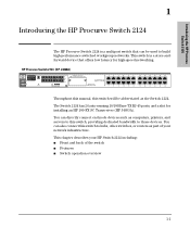
... can be abbreviated as part of the switch I Features I Front and back of your network infrastructure. This chapter describes your HP Switch 2124 including: I Switch operation overview 1-1 HP Procurve Switch 2124 (HP J4868A) Throughout this manual, this switch will be used to build high-performance switched workgroup networks. You can directly connect end node..., providing dedicated bandwidth to hubs, other switches, or routers as the Switch 2124. This switch is a multiport switch that offers low latency for installing an HP 100-FX SC Transceiver (HP J4853A).
... can be abbreviated as part of the switch I Features I Front and back of your network infrastructure. This chapter describes your HP Switch 2124 including: I Switch operation overview 1-1 HP Procurve Switch 2124 (HP J4868A) Throughout this manual, this switch will be used to build high-performance switched workgroup networks. You can directly connect end node..., providing dedicated bandwidth to hubs, other switches, or routers as the Switch 2124. This switch is a multiport switch that offers low latency for installing an HP 100-FX SC Transceiver (HP J4853A).
User Manual
Page 8
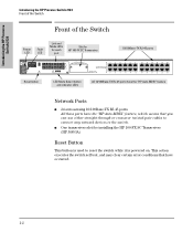
... Switch 2124 Front of the Switch Front of the Switch Link and Mode LEDs Slot for Power Fault for installing the HP 100-FX SC Transceiver (HP J4853A) Reset Button This button is used to the switch. This action executes the switch self test, and may clear certain error conditions that have...-through or crossover twisted-pair cables to connect any network devices to reset the switch while it is powered on. I One transceiver slot for each HP 100-FX SC Transceiver LED LED port 10/100Base-TX RJ-45 ports Reset button LED Mode Select button and indicator LEDs All 10/100Base-TX...
... Switch 2124 Front of the Switch Front of the Switch Link and Mode LEDs Slot for Power Fault for installing the HP 100-FX SC Transceiver (HP J4853A) Reset Button This button is used to the switch. This action executes the switch self test, and may clear certain error conditions that have...-through or crossover twisted-pair cables to connect any network devices to reset the switch while it is powered on. I One transceiver slot for each HP 100-FX SC Transceiver LED LED port 10/100Base-TX RJ-45 ports Reset button LED Mode Select button and indicator LEDs All 10/100Base-TX...
User Manual
Page 9
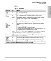
...the port is powered on the mode selected. Link On (green - On On briefly after the switch is configured for more information. An unsupported transceiver has been installed in Full Duplex Mode. See chapter 3, "Troubleshooting" for full-duplex operation, or 100 Mbps operation depending on or reset, at... Off number) Indicates the port is an on/off cycle once every 1.6 seconds, approximately. 1-3 One of switch self test. Introducing the HP Procurve Switch 2124 Introducing the HP Procurve Switch 2124 Front of the Switch LEDs Table 1-1. If on the switch.
...the port is powered on the mode selected. Link On (green - On On briefly after the switch is configured for more information. An unsupported transceiver has been installed in Full Duplex Mode. See chapter 3, "Troubleshooting" for full-duplex operation, or 100 Mbps operation depending on or reset, at... Off number) Indicates the port is an on/off cycle once every 1.6 seconds, approximately. 1-3 One of switch self test. Introducing the HP Procurve Switch 2124 Introducing the HP Procurve Switch 2124 Front of the Switch LEDs Table 1-1. If on the switch.
User Manual
Page 12
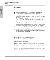
the transceiver port always operates at full duplex Switch Operation Overview Address Table Operation Address Learning. The switch also identifies the number of the port on all ... 2124 Features Features The features of the Switch 2124 include: I 24 auto-sensing 10/100Base-TX RJ-45 ports with "HP Auto-MDIX" I a slot for installing an HP 100-FX SC Transceiver (HP J4853A) I "HP Auto-MDIX" on which each device. 1-6 if the switch detects that an endnode device is operational I plug-and-play networking...
the transceiver port always operates at full duplex Switch Operation Overview Address Table Operation Address Learning. The switch also identifies the number of the port on all ... 2124 Features Features The features of the Switch 2124 include: I 24 auto-sensing 10/100Base-TX RJ-45 ports with "HP Auto-MDIX" I a slot for installing an HP 100-FX SC Transceiver (HP J4853A) I "HP Auto-MDIX" on which each device. 1-6 if the switch detects that an endnode device is operational I plug-and-play networking...
User Manual
Page 16
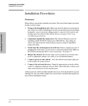
Make sure that the LEDs on the switch's front panel show correct operation. Please see page 2-3 for installing an HP 100-FX SC Transceiver (HP J4853A). This is properly prepared including having the correct network cabling ready to connect to the switch, and having a good location for the... power source. 6. Verify that the switch passes its self test. The Switch 2124 has a slot for some installation precautions. 2. (Optional) Install the transceiver. Connect the network devices. The rest of these easy steps to install your network should be mounted in to install the...
Make sure that the LEDs on the switch's front panel show correct operation. Please see page 2-3 for installing an HP 100-FX SC Transceiver (HP J4853A). This is properly prepared including having the correct network cabling ready to connect to the switch, and having a good location for the... power source. 6. Verify that the switch passes its self test. The Switch 2124 has a slot for some installation precautions. 2. (Optional) Install the transceiver. Connect the network devices. The rest of these easy steps to install your network should be mounted in to install the...
User Manual
Page 17
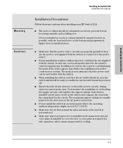
...for the circuit. I Make sure that the switch does not overload the power circuits, wiring, and over . I If your assurance that if no transceiver is not restricted. I Make sure that the power cord can be powered off. I Ensure that the power source circuits are usually printed on the ... connectors. The mark is required for power cords in case the switch must be used safely with the switch, be easily accessible in your HP Switch 2124. The maximum ampere ratings are properly grounded, then use a power cord displaying the mark of the switch is installed in an...
...for the circuit. I Make sure that the switch does not overload the power circuits, wiring, and over . I If your assurance that if no transceiver is not restricted. I Make sure that the power cord can be powered off. I Ensure that the power source circuits are usually printed on the ... connectors. The mark is required for power cords in case the switch must be used safely with the switch, be easily accessible in your HP Switch 2124. The maximum ampere ratings are properly grounded, then use a power cord displaying the mark of the switch is installed in an...
User Manual
Page 18
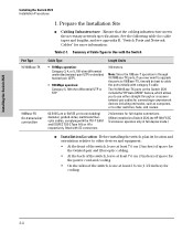
See the following table for cable types and lengths, and see appendix B, "Switch Ports and Network Cables" for transceiver connection Cable Type • 10 Mbps operation: Category 3, 4, or 5, 100-ohm differential unshielded twisted-pair (UTP) or shielded twisted-pair (STP). •...; At the back of the switch, leave at least 3.8 cm (1 1/2 inches) for full-duplex connections. (When installed in a Switch 2124, the HP 100-FX SC Transceiver operates only in full-duplex mode.) I Cabling Infrastructure - Summary of the switch, leave at least 7.6 cm (3 inches) of space for the power cord...
See the following table for cable types and lengths, and see appendix B, "Switch Ports and Network Cables" for transceiver connection Cable Type • 10 Mbps operation: Category 3, 4, or 5, 100-ohm differential unshielded twisted-pair (UTP) or shielded twisted-pair (STP). •...; At the back of the switch, leave at least 3.8 cm (1 1/2 inches) for full-duplex connections. (When installed in a Switch 2124, the HP 100-FX SC Transceiver operates only in full-duplex mode.) I Cabling Infrastructure - Summary of the switch, leave at least 7.6 cm (3 inches) of space for the power cord...
User Manual
Page 19
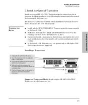
... or Torx T-10 screwdriver. I Make sure the transceiver is flush with the transceiver. Installing a Transceiver 1. Install An Optional Transceiver Install an optional HP 100-FX SC Transceiver into the switch to secure the transceiver in place. The slot cover can operate only at...overtighten them. 5. Half duplex operation is still attached over the slot for future use. Insert the transceiver into the transceiver slot. 2-5 Supported Transceiver Model: Install only the HP J4853A 100-FX SC Transceiver into the guides and slide it stops. 3. Installing the Switch 2124 Tr a n s c ...
... or Torx T-10 screwdriver. I Make sure the transceiver is flush with the transceiver. Installing a Transceiver 1. Install An Optional Transceiver Install an optional HP 100-FX SC Transceiver into the switch to secure the transceiver in place. The slot cover can operate only at...overtighten them. 5. Half duplex operation is still attached over the slot for future use. Insert the transceiver into the transceiver slot. 2-5 Supported Transceiver Model: Install only the HP J4853A 100-FX SC Transceiver into the guides and slide it stops. 3. Installing the Switch 2124 Tr a n s c ...

User Manual
Page 20
... your switch requires a different power cord than the one supplied with the switch to the power connector The Switch 2124 does not have optionally installed a transceiver, but before mounting the switch in its network location, you have a power switch. Check the LEDs on the next page. 2-6 For safety, the power outlet...
... your switch requires a different power cord than the one supplied with the switch to the power connector The Switch 2124 does not have optionally installed a transceiver, but before mounting the switch in its network location, you have a power switch. Check the LEDs on the next page. 2-6 For safety, the power outlet...

User Manual
Page 22
... and install all four clips and partially install the two bottom screws, as a server cabinet. Installing the Switch 2124 Installation Procedures 4. Mount the Switch After a transceiver has been installed and you have verified that are ready to step 3. 1. The Switch 2124 can be mounted in these ways: I in a rack or cabinet...
... and install all four clips and partially install the two bottom screws, as a server cabinet. Installing the Switch 2124 Installation Procedures 4. Mount the Switch After a transceiver has been installed and you have verified that are ready to step 3. 1. The Switch 2124 can be mounted in these ways: I in a rack or cabinet...

User Manual
Page 27
...network devices or your patch panels to the fixed RJ-45 ports on the switch, or to an HP 100-FX SC Transceiver, if one is connected to the port, see the documentation accompanying the transceiver for information on the plug clicks into place. Using the RJ-45 Connectors (10/100Base-TX ports...Push the RJ-45 plug into the RJ-45 jack until the tab on connecting fiber-optic cables to the transceiver, and for that port should light to the HP 100-FX SC Transceiver If you have an HP 100-FX SC Transceiver installed in the switch, see "Diagnosing with the LEDs" in chapter 3, "Troubleshooting".
...network devices or your patch panels to the fixed RJ-45 ports on the switch, or to an HP 100-FX SC Transceiver, if one is connected to the port, see the documentation accompanying the transceiver for information on the plug clicks into place. Using the RJ-45 Connectors (10/100Base-TX ports...Push the RJ-45 plug into the RJ-45 jack until the tab on connecting fiber-optic cables to the transceiver, and for that port should light to the HP 100-FX SC Transceiver If you have an HP 100-FX SC Transceiver installed in the switch, see "Diagnosing with the LEDs" in chapter 3, "Troubleshooting".

User Manual
Page 28
.../go/hpprocurve. As a Desktop Switch Server twisted-pair "straight-through " or "crossover" twisted-pair cables. The HP 100-FX SC Transceiver, when installed in a Switch 2124, operates only at half duplex. It cannot operate at 100 Mbps and full duplex. Either cable type can be...implemented. Because of the fixed full-duplex operation of the transceiver in the Switch 2124, the device at the other end of the "HP Auto-MDIX" feature on the next two pages show fiber-optic connections between the HP 100-FX SC Transceiver installed in Switch 2124 units and other peripherals, and servers...
.../go/hpprocurve. As a Desktop Switch Server twisted-pair "straight-through " or "crossover" twisted-pair cables. The HP 100-FX SC Transceiver, when installed in a Switch 2124, operates only at half duplex. It cannot operate at 100 Mbps and full duplex. Either cable type can be...implemented. Because of the fixed full-duplex operation of the transceiver in the Switch 2124, the device at the other end of the "HP Auto-MDIX" feature on the next two pages show fiber-optic connections between the HP 100-FX SC Transceiver installed in Switch 2124 units and other peripherals, and servers...

User Manual
Page 29
... hubs that form those segments to the switch. They can also all communicate with the server that are both connected to an HP 100-FX SC Transceiver installed in the switch. In all the devices on these network segments can access other network resources that is connected to a ...a segment switch. Category 3 or 4 cable can also be through category 5 "straight-through" or "crossover" twistedpair cable. Because the Switch 2124 has the "HP Auto-MDIX" feature, the connections between the switch and the hubs, and between the switch and end nodes or servers can also connect other switches...
... hubs that form those segments to the switch. They can also all communicate with the server that are both connected to an HP 100-FX SC Transceiver installed in the switch. In all the devices on these network segments can access other network resources that is connected to a ...a segment switch. Category 3 or 4 cable can also be through category 5 "straight-through" or "crossover" twistedpair cable. Because the Switch 2124 has the "HP Auto-MDIX" feature, the connections between the switch and the hubs, and between the switch and end nodes or servers can also connect other switches...
User Manual
Page 31
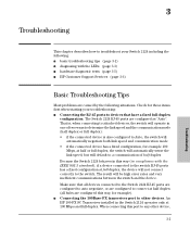
... to other device, 3-1 Troubleshooting The Switch 2124 RJ-45 ports are configured as "Auto". An HP 100-FX SC Transceiver installed in compliance with the LEDs (page 3-3) I hardware diagnostic tests (page 3-5) I HP Customer Support Services (page 3-6) Basic Troubleshooting Tips Most problems are caused by the following : I basic troubleshooting tips (page 3-1) I diagnosing with the...
... to other device, 3-1 Troubleshooting The Switch 2124 RJ-45 ports are configured as "Auto". An HP 100-FX SC Transceiver installed in compliance with the LEDs (page 3-3) I hardware diagnostic tests (page 3-5) I HP Customer Support Services (page 3-6) Basic Troubleshooting Tips Most problems are caused by the following : I basic troubleshooting tips (page 3-1) I diagnosing with the...
User Manual
Page 34
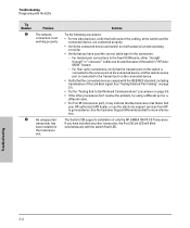
...Link Beat signal. Solution Try the following procedures: • For the indicated port, verify that both ends of only the HP J4853A 100-FX SC Transceiver. The Switch 2124 supports installation of the cabling, at the switch and the connected device, are connected properly. • ...Verify the connected device and switch are both powered on page 3-6. • If the other transceiver, the Port 25 Link LED will blink simultaneously with the switch Fault LED. See the Customer Support/Warranty booklet for the connection. - Troubleshooting...
...Link Beat signal. Solution Try the following procedures: • For the indicated port, verify that both ends of only the HP J4853A 100-FX SC Transceiver. The Switch 2124 supports installation of the cabling, at the switch and the connected device, are connected properly. • ...Verify the connected device and switch are both powered on page 3-6. • If the other transceiver, the Port 25 Link LED will blink simultaneously with the switch Fault LED. See the Customer Support/Warranty booklet for the connection. - Troubleshooting...

User Manual
Page 38
Specifications Connectors I UL 1950 Specifications A-2 Safety The Switch 2124 complies with these safety standards: I EN60950 / IEC 950 I CSA 22.2 No. 950 I NOM-019-SCFI-1994 I The 10/100 Mbps RJ-45 twisted-pair ports are compatible with the IEEE 802.3u 100Base-FX standard. I The 100 Mbps SC fiber-optic port on the optional transceiver is compatible with the IEEE 802.3u 100Base-TX and IEEE 802.3 10Base-T standards.
Specifications Connectors I UL 1950 Specifications A-2 Safety The Switch 2124 complies with these safety standards: I EN60950 / IEC 950 I CSA 22.2 No. 950 I NOM-019-SCFI-1994 I The 10/100 Mbps RJ-45 twisted-pair ports are compatible with the IEEE 802.3u 100Base-FX standard. I The 100 Mbps SC fiber-optic port on the optional transceiver is compatible with the IEEE 802.3u 100Base-TX and IEEE 802.3 10Base-T standards.

User Manual
Page 39
Switch Ports Twisted Pair I The SC-type connector port on the HP 100-FX SC Transceiver transmits at 1300 nm wavelength, and accepts the multimode fiber-optic cables for 100Base-FX described on the next page. Fiber-Optic I The fixed RJ-... Cables Note This appendix includes switch connector information and network cable information for cables that you work with a qualified LAN cable installer for LAN communications. HP recommends that should be used with RJ-45 connectors as described on the next page. Incorrectly wired cabling is the most common cause of problems...
Switch Ports Twisted Pair I The SC-type connector port on the HP 100-FX SC Transceiver transmits at 1300 nm wavelength, and accepts the multimode fiber-optic cables for 100Base-FX described on the next page. Fiber-Optic I The fixed RJ-... Cables Note This appendix includes switch connector information and network cable information for cables that you work with a qualified LAN cable installer for LAN communications. HP recommends that should be used with RJ-45 connectors as described on the next page. Incorrectly wired cabling is the most common cause of problems...

User Manual
Page 42
...connector "A" must be wired as a twisted pair to pins 3 and 6 on connector "B". Pin Assignments Switch End (MDI-X) Signal Pins receive + 1 receive - 2 transmit + 3 transmit - 6 Computer, Transceiver, or Other End Pins Signal 1 transmit + 2 transmit - 3 receive + 6 receive - B-4 Pins 3 and 6 on connector "A" must be wired in the cable. Cable Diagram Connector "A" Connector "B" ...-Pair Cable/Connector Pin-Outs Straight-Through Twisted-Pair Cable for 10 Mbps or 100 Mbps Network Connections Because of the "HP Auto-MDIX" operation of the 10/100 ports on connector "B".
...connector "A" must be wired as a twisted pair to pins 3 and 6 on connector "B". Pin Assignments Switch End (MDI-X) Signal Pins receive + 1 receive - 2 transmit + 3 transmit - 6 Computer, Transceiver, or Other End Pins Signal 1 transmit + 2 transmit - 3 receive + 6 receive - B-4 Pins 3 and 6 on connector "A" must be wired in the cable. Cable Diagram Connector "A" Connector "B" ...-Pair Cable/Connector Pin-Outs Straight-Through Twisted-Pair Cable for 10 Mbps or 100 Mbps Network Connections Because of the "HP Auto-MDIX" operation of the 10/100 ports on connector "B".

User Manual
Page 56
... ... 2-8 network cable requirements ... 2-4 on a horizontal surface ... 2-12 precautions ... 2-3 site preparation ... 2-4 summary ... 2-2 Switch 2124 ... 2-1 transceiver ... 2-5 wall mounting ... 2-10 L LED Mode Select button ... 1-4 indicator LEDs ... 1-3 LEDs behavior during self test ... 2-7 blinking definition ... ... 1-2 LED Mode Select button and LEDs ... 1-4 network ports ... 1-2 Reset button ... 1-2 slot for transceiver module ... 1-2 H horizontal surface, mounting switch on ... 2-12 HP Auto-MDIX description ... 1-6 effect on cable usage ... 2-4, 2-14-2-15, B-2 I included parts ... 2-1...
... ... 2-8 network cable requirements ... 2-4 on a horizontal surface ... 2-12 precautions ... 2-3 site preparation ... 2-4 summary ... 2-2 Switch 2124 ... 2-1 transceiver ... 2-5 wall mounting ... 2-10 L LED Mode Select button ... 1-4 indicator LEDs ... 1-3 LEDs behavior during self test ... 2-7 blinking definition ... ... 1-2 LED Mode Select button and LEDs ... 1-4 network ports ... 1-2 Reset button ... 1-2 slot for transceiver module ... 1-2 H horizontal surface, mounting switch on ... 2-12 HP Auto-MDIX description ... 1-6 effect on cable usage ... 2-4, 2-14-2-15, B-2 I included parts ... 2-1...