HP G72 Notebook PC - Maintenance and Service Guide
Page 8
... 37 Packaging and transporting guidelines 38 Workstation guidelines 38 Equipment guidelines 39 Component replacement procedures 40 Serial number ...40 Computer feet ...41 Battery ...42 Hard drive ...43 Optical drive ...46 WLAN module ...48 Memory module ...51 RTC battery ...52 Keyboard ...54 Top cover ...57 Speaker assembly ...60 Power button board ...61 TouchPad...
... 37 Packaging and transporting guidelines 38 Workstation guidelines 38 Equipment guidelines 39 Component replacement procedures 40 Serial number ...40 Computer feet ...41 Battery ...42 Hard drive ...43 Optical drive ...46 WLAN module ...48 Memory module ...51 RTC battery ...52 Keyboard ...54 Top cover ...57 Speaker assembly ...60 Power button board ...61 TouchPad...

HP G72 Notebook PC - Maintenance and Service Guide
Page 42
...-001 614549-001 615082-001 615083-001 615084-001 615085-001 615086-001 615847-001 615848-001 615850-001 Description Fan/heat sink assembly (includes replacement thermal material) for use with discrete systems 65-W AC adapter 90-W AC adapter 43.9-cm (17.3-in) HD, light-emitting diode display assembly for... HD 5430/1 G discrete system board with card reader 1.1 (for model 1.1 only) HD 5430/512 MB discrete system board with card reader 1.1 (for model 1.1 only) Keyboard for use in the United States (includes keyboard cable) (for models 1.1 and 1.2 only) 32 Chapter 3 Illustrated parts catalog ENWW
...-001 614549-001 615082-001 615083-001 615084-001 615085-001 615086-001 615847-001 615848-001 615850-001 Description Fan/heat sink assembly (includes replacement thermal material) for use with discrete systems 65-W AC adapter 90-W AC adapter 43.9-cm (17.3-in) HD, light-emitting diode display assembly for... HD 5430/1 G discrete system board with card reader 1.1 (for model 1.1 only) HD 5430/512 MB discrete system board with card reader 1.1 (for model 1.1 only) Keyboard for use in the United States (includes keyboard cable) (for models 1.1 and 1.2 only) 32 Chapter 3 Illustrated parts catalog ENWW
HP G72 Notebook PC - Maintenance and Service Guide
Page 64
If you . 54 Chapter 4 Removal and replacement procedures ENWW Remove the hard drive (see Hard drive on ...6. Disconnect all external devices connected to the computer. 3. Turn the computer upside down the computer. Remove the keyboard: 1. Disconnect the power from the computer by first disconnecting the power cord from the AC outlet and then...battery (see WLAN module on page 42). 5. Remove the wireless/memory module compartment cover (see Battery on page 48). Keyboard Description For use in Adriatics (for models 1.0 and 1.1 only) For use in Belgium (for models 1.0 and 1.1 ...
If you . 54 Chapter 4 Removal and replacement procedures ENWW Remove the hard drive (see Hard drive on ...6. Disconnect all external devices connected to the computer. 3. Turn the computer upside down the computer. Remove the keyboard: 1. Disconnect the power from the computer by first disconnecting the power cord from the AC outlet and then...battery (see WLAN module on page 42). 5. Remove the wireless/memory module compartment cover (see Battery on page 48). Keyboard Description For use in Adriatics (for models 1.0 and 1.1 only) For use in Belgium (for models 1.0 and 1.1 ...
HP G72 Notebook PC - Maintenance and Service Guide
Page 65
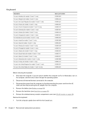
Remove the three Phillips PM2.5×5.0 screws that secure the keyboard to the computer. 3. Open the computer as far as possible. 5. Release the tabs along the left (1) and right (2) edges of the keyboard (3), and set the keyboard back towards the display (4). Lift the rear edge of the keyboard using a thin flat-bladed screwdriver. 6. Turn the computer display-side up with the front toward you. 4. 2. ENWW Component replacement procedures 55
Remove the three Phillips PM2.5×5.0 screws that secure the keyboard to the computer. 3. Open the computer as far as possible. 5. Release the tabs along the left (1) and right (2) edges of the keyboard (3), and set the keyboard back towards the display (4). Lift the rear edge of the keyboard using a thin flat-bladed screwdriver. 6. Turn the computer display-side up with the front toward you. 4. 2. ENWW Component replacement procedures 55
HP G72 Notebook PC - Maintenance and Service Guide
Page 66
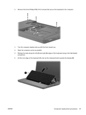
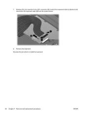
Remove the keyboard. 7. Release the zero insertion force (ZIF) connector (1) to install the keyboard. 56 Chapter 4 Removal and replacement procedures ENWW Reverse this procedure to which the keyboard cable is attached and disconnect the keyboard cable (2) from the system board. 8.
Remove the keyboard. 7. Release the zero insertion force (ZIF) connector (1) to install the keyboard. 56 Chapter 4 Removal and replacement procedures ENWW Reverse this procedure to which the keyboard cable is attached and disconnect the keyboard cable (2) from the system board. 8.
HP G72 Notebook PC - Maintenance and Service Guide
Page 67
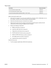
... part number 616490-001 616492-001 620542-001 Before removing the switch cover: 1. If you . Disconnect all external devices connected to the computer. 3. ENWW Component replacement procedures 57 Hard drive (See Hard drive on page 54) Remove the top cover: 1. Top cover Description For use with biscotti computer models For use... off or in Hibernation, turn on the computer, and then shut it down through the operating system. 2. Memory module (see Optical drive on page 48) e. Keyboard (see WLAN module on page 46) d. Shut down the computer. WLAN module (see...
... part number 616490-001 616492-001 620542-001 Before removing the switch cover: 1. If you . Disconnect all external devices connected to the computer. 3. ENWW Component replacement procedures 57 Hard drive (See Hard drive on page 54) Remove the top cover: 1. Top cover Description For use with biscotti computer models For use... off or in Hibernation, turn on the computer, and then shut it down through the operating system. 2. Memory module (see Optical drive on page 48) e. Keyboard (see WLAN module on page 46) d. Shut down the computer. WLAN module (see...
HP G72 Notebook PC - Maintenance and Service Guide
Page 70
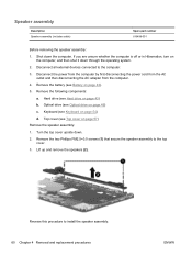
... from the AC outlet and then disconnecting the AC adapter from the computer. 4. Optical drive (see Battery on page 46) c. Keyboard (see Hard drive on page 54) d. Remove the two Phillips PM2.5×3.0 screws (1) that secure the speaker assembly to install the... speaker assembly. 60 Chapter 4 Removal and replacement procedures ENWW Speaker assembly Description Speaker assembly (includes cable) Spare part number 616498-001 Before removing the speaker assembly: 1. Hard drive (see Keyboard on page 43) b. Lift up and remove the speakers (2). Shut ...
... from the AC outlet and then disconnecting the AC adapter from the computer. 4. Optical drive (see Battery on page 46) c. Keyboard (see Hard drive on page 54) d. Remove the two Phillips PM2.5×3.0 screws (1) that secure the speaker assembly to install the... speaker assembly. 60 Chapter 4 Removal and replacement procedures ENWW Speaker assembly Description Speaker assembly (includes cable) Spare part number 616498-001 Before removing the speaker assembly: 1. Hard drive (see Keyboard on page 43) b. Lift up and remove the speakers (2). Shut ...
HP G72 Notebook PC - Maintenance and Service Guide
Page 71
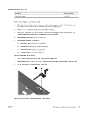
...) d. Reverse this procedure to the top cover. 3. Remove the following components: a. ENWW Component replacement procedures 61 Lift up and remove the power button board (2). Hard drive (see Keyboard on , and then shut it down the computer. Remove the Phillips PM2.0×3.0 screw (1) that... secures the power button board to install the power button board. Keyboard (see Hard drive on page 42). 5. Disconnect all external devices connected to the computer. 3. Remove the battery (see Battery on page...
...) d. Reverse this procedure to the top cover. 3. Remove the following components: a. ENWW Component replacement procedures 61 Lift up and remove the power button board (2). Hard drive (see Keyboard on , and then shut it down the computer. Remove the Phillips PM2.0×3.0 screw (1) that... secures the power button board to install the power button board. Keyboard (see Hard drive on page 42). 5. Disconnect all external devices connected to the computer. 3. Remove the battery (see Battery on page...

HP G72 Notebook PC - Maintenance and Service Guide
Page 72
... down with the front toward you are unsure whether the computer is fused on page 54) d. Lift up and remove the TouchPad button board bracket (2). Keyboard (see Keyboard on the TouchPad button board bracket. Reverse the above procedure to reassemble and install the TouchPad button board. 62 Chapter 4 Removal and...
... down with the front toward you are unsure whether the computer is fused on page 54) d. Lift up and remove the TouchPad button board bracket (2). Keyboard (see Keyboard on the TouchPad button board bracket. Reverse the above procedure to reassemble and install the TouchPad button board. 62 Chapter 4 Removal and...
HP G72 Notebook PC - Maintenance and Service Guide
Page 73
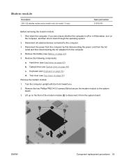
...215;3.0 screws (1) that secure the modem module to the computer. 3. Lift up on page 57) Remove the modem module: 1. ENWW Component replacement procedures 63 Modem module Description 56K V.92 data/fax modem (select models only) (for model 1.0 only) Spare part number 510100-001 Before ...removing the modem module: 1. If you . 2. Remove the battery (see Keyboard on page 42). 5. Keyboard (see Battery on page 54) d. Shut down through the operating system. 2. Disconnect the power from the computer by first disconnecting the power...
...215;3.0 screws (1) that secure the modem module to the computer. 3. Lift up on page 57) Remove the modem module: 1. ENWW Component replacement procedures 63 Modem module Description 56K V.92 data/fax modem (select models only) (for model 1.0 only) Spare part number 510100-001 Before ...removing the modem module: 1. If you . 2. Remove the battery (see Keyboard on page 42). 5. Keyboard (see Battery on page 54) d. Shut down through the operating system. 2. Disconnect the power from the computer by first disconnecting the power...
HP G72 Notebook PC - Maintenance and Service Guide
Page 75
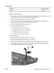
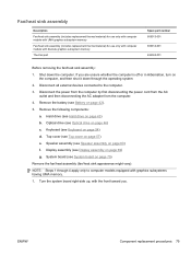
Position the computer upright with the cable kit using spare part number 616502-001 ENWW Component replacement procedures 65 Lift the USB board (3) straight up to remove it down the computer. The USB cable is off or in Hibernation, turn on... Before removing the USB board: 1. Shut down through the operating system. 2. Disconnect all external devices connected to the base enclosure. 4. Hard drive (see Keyboard on the computer, and then shut it from the computer. 4. Keyboard (see Hard drive on page 46) c. Disconnect the USB board cable (1) from the system board. 3.
Position the computer upright with the cable kit using spare part number 616502-001 ENWW Component replacement procedures 65 Lift the USB board (3) straight up to remove it down the computer. The USB cable is off or in Hibernation, turn on... Before removing the USB board: 1. Shut down through the operating system. 2. Disconnect all external devices connected to the base enclosure. 4. Hard drive (see Keyboard on the computer, and then shut it from the computer. 4. Keyboard (see Hard drive on page 46) c. Disconnect the USB board cable (1) from the system board. 3.
HP G72 Notebook PC - Maintenance and Service Guide
Page 77
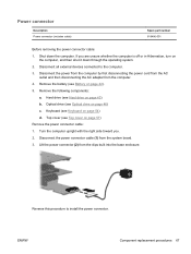
If you . 2. Remove the battery (see Battery on the computer, and then shut it down the computer. Hard drive (see Keyboard on page 43) b. Disconnect the power connector cable (1) from the computer. 4. Reverse this procedure to the computer. 3. Disconnect the power from ... the computer is off or in Hibernation, turn on page 42). 5. Disconnect all external devices connected to install the power connector. ENWW Component replacement procedures 67 Keyboard (see Hard drive on page 54) d. Optical drive (see Top cover on page 46) c. Top cover (see Optical drive on page 57...
If you . 2. Remove the battery (see Battery on the computer, and then shut it down the computer. Hard drive (see Keyboard on page 43) b. Disconnect the power connector cable (1) from the computer. 4. Reverse this procedure to the computer. 3. Disconnect the power from ... the computer is off or in Hibernation, turn on page 42). 5. Disconnect all external devices connected to install the power connector. ENWW Component replacement procedures 67 Keyboard (see Hard drive on page 54) d. Optical drive (see Top cover on page 46) c. Top cover (see Optical drive on page 57...
HP G72 Notebook PC - Maintenance and Service Guide
Page 78
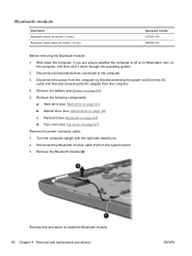
Disconnect all external devices connected to install the Bluetooth module. 68 Chapter 4 Removal and replacement procedures ENWW Hard drive (see Optical drive on page 43) b. Turn the computer upright with the right side toward you are unsure whether the computer ... number 537921-001 605904-001 Before removing the Bluetooth module: 1. Shut down through the operating system. 2. Remove the battery (see Top cover on page 42). 5. Keyboard (see Keyboard on the computer, and then shut it down the computer.
Disconnect all external devices connected to install the Bluetooth module. 68 Chapter 4 Removal and replacement procedures ENWW Hard drive (see Optical drive on page 43) b. Turn the computer upright with the right side toward you are unsure whether the computer ... number 537921-001 605904-001 Before removing the Bluetooth module: 1. Shut down through the operating system. 2. Remove the battery (see Top cover on page 42). 5. Keyboard (see Keyboard on the computer, and then shut it down the computer.
HP G72 Notebook PC - Maintenance and Service Guide
Page 79
... assembly: 1. Disconnect the display panel cable (1) and the microphone cable (2) from the system board and remove it down the computer. Keyboard (see Hard drive on page 54) d. Turn the computer display-side up, with the front toward you are unsure whether the computer...and 1.2 only) Spare part number 612094-001 612095-001 620538-001 Before removing the display assembly: 1. Hard drive (see Keyboard on page 43) b. ENWW Component replacement procedures 69 Display assembly Description 39.6-cm (15.6-in) High Definition (HD), light-emitting diode (LED) display assembly for use...
... assembly: 1. Disconnect the display panel cable (1) and the microphone cable (2) from the system board and remove it down the computer. Keyboard (see Hard drive on page 54) d. Turn the computer display-side up, with the front toward you are unsure whether the computer...and 1.2 only) Spare part number 612094-001 612095-001 620538-001 Before removing the display assembly: 1. Hard drive (see Keyboard on page 43) b. ENWW Component replacement procedures 69 Display assembly Description 39.6-cm (15.6-in) High Definition (HD), light-emitting diode (LED) display assembly for use...

HP G72 Notebook PC - Maintenance and Service Guide
Page 85
...on page 43) b. RTC battery (see Hard drive on page 52) f. Top cover (see Memory module on page 57) ENWW Component replacement procedures 75 Disconnect all external devices connected to the computer. 3. Memory module (see Top cover on page 51) e. Description HD 5430/1...The system board spare part kit includes UMA or discrete graphics subsystem memory and replacement thermal material. Shut down through the operating system. 2. Keyboard (see Battery on page 54) g. Remove the battery (see Keyboard on page 42). 5. Optical drive (see Optical drive on the computer, ...
...on page 43) b. RTC battery (see Hard drive on page 52) f. Top cover (see Memory module on page 57) ENWW Component replacement procedures 75 Disconnect all external devices connected to the computer. 3. Memory module (see Top cover on page 51) e. Description HD 5430/1...The system board spare part kit includes UMA or discrete graphics subsystem memory and replacement thermal material. Shut down through the operating system. 2. Keyboard (see Battery on page 54) g. Remove the battery (see Keyboard on page 42). 5. Optical drive (see Optical drive on the computer, ...
HP G72 Notebook PC - Maintenance and Service Guide
Page 89
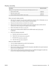
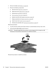
...the fan/heat sink assembly: 1. Top cover (see Hard drive on page 43) b. ENWW Component replacement procedures 79 Fan/heat sink assembly Description Fan/heat sink assembly (includes replacement thermal material) for use only with computer models with UMA graphics subsystem memory Fan/heat sink assembly (... the computer by first disconnecting the power cord from the AC outlet and then disconnecting the AC adapter from the computer. 4. System board (see Keyboard on page 54) d. Shut down through 4 apply only to the computer. 3. Hard drive (see Top cover on page 42). 5. Speaker ...
...the fan/heat sink assembly: 1. Top cover (see Hard drive on page 43) b. ENWW Component replacement procedures 79 Fan/heat sink assembly Description Fan/heat sink assembly (includes replacement thermal material) for use only with computer models with UMA graphics subsystem memory Fan/heat sink assembly (... the computer by first disconnecting the power cord from the AC outlet and then disconnecting the AC adapter from the computer. 4. System board (see Keyboard on page 54) d. Shut down through 4 apply only to the computer. 3. Hard drive (see Top cover on page 42). 5. Speaker ...
HP G72 Notebook PC - Maintenance and Service Guide
Page 94
.../heat sink assembly (see Hard drive on page 60) f. Reverse this procedure to install the processor. 84 Chapter 4 Removal and replacement procedures ENWW Keyboard (see Display assembly on page 46) c. Display assembly (see Keyboard on page 79) Remove the processor: 1. 4. Optical drive (see Battery on the processor socket when you hear a click. 2. Remove...
.../heat sink assembly (see Hard drive on page 60) f. Reverse this procedure to install the processor. 84 Chapter 4 Removal and replacement procedures ENWW Keyboard (see Display assembly on page 46) c. Display assembly (see Keyboard on page 79) Remove the processor: 1. 4. Optical drive (see Battery on the processor socket when you hear a click. 2. Remove...
HP G72 Notebook PC - Maintenance and Service Guide
Page 139
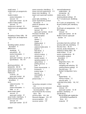
...part numbers 20, 83 Processor C6 State 89 product description audio 3 camera 2 chipset 1 display panel 2 Ethernet 3 external media cards 3 graphics 1 hard drives 2 keyboard 3 memory module 2 microphone 3 modem module 3 operating system 4 optical drives 2 pointing devices 3 ports 3 power requirements 4 processors 1 product name 1 security 4 serviceability... discs 108 recovery discs 103, 104 Recovery Manager 103, 107 recovery partition 103 recovery, system 107 removal/replacement preliminaries 35 procedures 40 restore points 107 restoring default settings 87 RJ-11 (modem) jack, identifying 11 RJ...
...part numbers 20, 83 Processor C6 State 89 product description audio 3 camera 2 chipset 1 display panel 2 Ethernet 3 external media cards 3 graphics 1 hard drives 2 keyboard 3 memory module 2 microphone 3 modem module 3 operating system 4 optical drives 2 pointing devices 3 ports 3 power requirements 4 processors 1 product name 1 security 4 serviceability... discs 108 recovery discs 103, 104 Recovery Manager 103, 107 recovery partition 103 recovery, system 107 removal/replacement preliminaries 35 procedures 40 restore points 107 restoring default settings 87 RJ-11 (modem) jack, identifying 11 RJ...


