Service Guide
Page 4
... 4 Removal and replacement procedures Preliminary replacement requirements 4-1 Tools required 4-1 Service considerations 4-1 Grounding guidelines 4-2 Unknown user password 4-4 Component replacement procedures 4-5 Serial number 4-5 Computer feet 4-6 Battery 4-7 Optical drive 4-8 Hard drive 4-10 RTC battery 4-12 Memory module 4-13 WLAN module 4-15 Keyboard 4-17 Keyboard cover 4-20 Contents iv
... 4 Removal and replacement procedures Preliminary replacement requirements 4-1 Tools required 4-1 Service considerations 4-1 Grounding guidelines 4-2 Unknown user password 4-4 Component replacement procedures 4-5 Serial number 4-5 Computer feet 4-6 Battery 4-7 Optical drive 4-8 Hard drive 4-10 RTC battery 4-12 Memory module 4-13 WLAN module 4-15 Keyboard 4-17 Keyboard cover 4-20 Contents iv
Service Guide
Page 5
... Computer specifications 6-1 16 and 15.6-inch WXGA display specifications 6-2 Hard drive specifications 6-2 DVD±RW and CD-RW SuperMulti Double-Layer Combo Drive specifications 6-3 DVD±RW and CD-RW SuperMulti Double-Layer Combo Drive with LightScribe specifications. . . . . . 6-4 Blu-ray... ROM DVD±RW SuperMulti DL Drive specifications 6-4 System DMA specifications 6-5 System interrupt ...
... Computer specifications 6-1 16 and 15.6-inch WXGA display specifications 6-2 Hard drive specifications 6-2 DVD±RW and CD-RW SuperMulti Double-Layer Combo Drive specifications 6-3 DVD±RW and CD-RW SuperMulti Double-Layer Combo Drive with LightScribe specifications. . . . . . 6-4 Blu-ray... ROM DVD±RW SuperMulti DL Drive specifications 6-4 System DMA specifications 6-5 System interrupt ...
Service Guide
Page 10
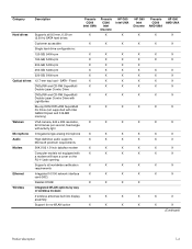
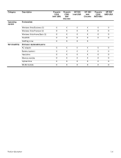
... Description Presario CQ60 Intel UMA Hard drives Supports all worldwide certification X requirements Ethernet Integrated 10/100 network interface X card (NIC) Realtek 8102E X Wireless Integrated WLAN options by way of wireless module: 2 wireless antennae built into display X assembly Support for no-WLAN option X Presario CQ60 Intel Discrete X HP G60 Intel UMA X X X X X X X X X X X X X X X X X X X X X X X X X X X X X X X X X X X X X X X X X HP G60 Intel Discrete X X X X X X X X X X X X X X X X X X X X X Presario HP G60 CQ60 AMD UMA...
... Description Presario CQ60 Intel UMA Hard drives Supports all worldwide certification X requirements Ethernet Integrated 10/100 network interface X card (NIC) Realtek 8102E X Wireless Integrated WLAN options by way of wireless module: 2 wireless antennae built into display X assembly Support for no-WLAN option X Presario CQ60 Intel Discrete X HP G60 Intel UMA X X X X X X X X X X X X X X X X X X X X X X X X X X X X X X X X X X X X X X X X X HP G60 Intel Discrete X X X X X X X X X X X X X X X X X X X X X Presario HP G60 CQ60 AMD UMA...
Service Guide
Page 12
... Preinstalled: Windows Vista Business 32 Windows Vista Premium 32 Windows Vista Home Basic 32 FreeDOS RedFlag Linux End-user replaceable parts: AC adapter Battery (system) Hard drive Memory module Optical drive WLAN module Presario CQ60 Intel UMA Presario CQ60 Intel Discrete HP G60 Intel UMA HP G60 Intel Discrete Presario HP G60 CQ60 AMD UMA AMD UMA X X X X X X X X X X X X X X X X X X X X X X X X X X X X X X X X X X X X X X X X X X X X X X X X X X X X X X X X X X X X X X X X Product description...
... Preinstalled: Windows Vista Business 32 Windows Vista Premium 32 Windows Vista Home Basic 32 FreeDOS RedFlag Linux End-user replaceable parts: AC adapter Battery (system) Hard drive Memory module Optical drive WLAN module Presario CQ60 Intel UMA Presario CQ60 Intel Discrete HP G60 Intel UMA HP G60 Intel Discrete Presario HP G60 CQ60 AMD UMA AMD UMA X X X X X X X X X X X X X X X X X X X X X X X X X X X X X X X X X X X X X X X X X X X X X X X X X X X X X X X X X X X X X X X X Product description...
Service Guide
Page 14
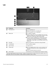
...On: Num lock is on or the integrated numeric keypad is turned on. ■ Amber: All wireless devices are fully charged. Blinking: The hard drive or optical drive is being accessed. 4 TouchPad light White: TouchPad is enabled. 5 Caps lock light On: Caps lock is on. 6 Wireless light 7 ...or a Bluetooth® device, is enabled. *The 2 power lights display the same information. Lights Item Component 1 Power lights* (2) 2 Battery light 3 Drive light Description ■ On: The computer is on. ■ Blinking: The computer is in the Sleep state. ■ Off: The computer is off ...
...On: Num lock is on or the integrated numeric keypad is turned on. ■ Amber: All wireless devices are fully charged. Blinking: The hard drive or optical drive is being accessed. 4 TouchPad light White: TouchPad is enabled. 5 Caps lock light On: Caps lock is on. 6 Wireless light 7 ...or a Bluetooth® device, is enabled. *The 2 power lights display the same information. Lights Item Component 1 Power lights* (2) 2 Battery light 3 Drive light Description ■ On: The computer is on. ■ Blinking: The computer is in the Sleep state. ■ Off: The computer is off ...
Service Guide
Page 18
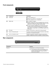
... (microphone) jack 5 Audio-out (headphone) jack Rear components Component Vents (2) Description ■ On: The computer is on and off during routine operation. Blinking: The hard drive or optical drive is plugged into an external power source, the light stays off when all batteries in Hibernation. ■ On: A battery is charging. ■ Blinking: A battery...
... (microphone) jack 5 Audio-out (headphone) jack Rear components Component Vents (2) Description ■ On: The computer is on and off during routine operation. Blinking: The hard drive or optical drive is plugged into an external power source, the light stays off when all batteries in Hibernation. ■ On: A battery is charging. ■ Blinking: A battery...
Service Guide
Page 20
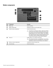
... and then receive a warning message, remove the module to cool internal components and prevent overheating. Holds the hard drive. External component identification 2-8 Bottom components Item Component 1 Battery bay 2 Battery release latch 3 WLAN module compartment 4 Vents (4) 5 Memory module ...compartment 6 Hard drive bay Function Holds the battery. Holds the WLAN module. Ä To prevent an unresponsive system, replace the wireless module with ...
... and then receive a warning message, remove the module to cool internal components and prevent overheating. Holds the hard drive. External component identification 2-8 Bottom components Item Component 1 Battery bay 2 Battery release latch 3 WLAN module compartment 4 Vents (4) 5 Memory module ...compartment 6 Hard drive bay Function Holds the battery. Holds the WLAN module. Ä To prevent an unresponsive system, replace the wireless module with ...

Service Guide
Page 24
..., Digital Media Slot, HDMI port, and replacement thermal material) 485219-001 UMA system board, GL40 (for more Plastics Kit spare part information) 486621-001 (9a) Hard drive cover (9b) Memory module compartment cover (9c) WLAN module compartment cover (10) USB board (does not include USB board cable) 486633-001 USB board cable...
..., Digital Media Slot, HDMI port, and replacement thermal material) 485219-001 UMA system board, GL40 (for more Plastics Kit spare part information) 486621-001 (9a) Hard drive cover (9b) Memory module compartment cover (9c) WLAN module compartment cover (10) USB board (does not include USB board cable) 486633-001 USB board cable...
Service Guide
Page 26
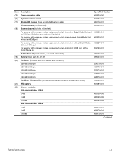
... equipped with a built-in modem, HDMI port, without Digital Media Slot Rubber Feet Kit (not illustrated, includes 6 rubber feet) Battery, 6-cell, 2.20-Ah, 47-Wh Hard drive (includes hard drive bracket and connector) 320-GB, 5400-rpm 250-GB, 5400-rpm 200-GB, 5400-rpm 160-GB, 5400-rpm 120-GB, 5400-rpm... Hard Drive Hardware Kit (not illustrated, includes connector, bracket, and screws) RTC battery Memory modules PC2-6400, 667-MHz, DDR2 2-GB 1-GB 512-MB PC2-5300, 667-...
... equipped with a built-in modem, HDMI port, without Digital Media Slot Rubber Feet Kit (not illustrated, includes 6 rubber feet) Battery, 6-cell, 2.20-Ah, 47-Wh Hard drive (includes hard drive bracket and connector) 320-GB, 5400-rpm 250-GB, 5400-rpm 200-GB, 5400-rpm 160-GB, 5400-rpm 120-GB, 5400-rpm... Hard Drive Hardware Kit (not illustrated, includes connector, bracket, and screws) RTC battery Memory modules PC2-6400, 667-MHz, DDR2 2-GB 1-GB 512-MB PC2-5300, 667-...
Service Guide
Page 31
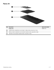
Plastics Kit Item Description Plastics Kit: 1 WLAN module compartment cover (includes 1 captive screw, secured by a C-clip) 2 Memory module compartment cover (includes 2 captive screws, secured by C-clips) 3 Hard drive cover (includes 2 captive screws, secured by C-clips) Spare part number 486621-001 Illustrated parts catalog 3-11
Plastics Kit Item Description Plastics Kit: 1 WLAN module compartment cover (includes 1 captive screw, secured by a C-clip) 2 Memory module compartment cover (includes 2 captive screws, secured by C-clips) 3 Hard drive cover (includes 2 captive screws, secured by C-clips) Spare part number 486621-001 Illustrated parts catalog 3-11

Service Guide
Page 32
Mass storage devices Item Description 1 Hard drive (includes connector and bracket) 320-GB, 5400-rpm 250-GB, 5400-rpm 200-GB, 5400-rpm 160-GB, 5400-rpm 120-GB, 5400-rpm Hard Drive Hardware Kit (includes connector, bracket, and screws) 2 Optical drive (includes bezel and bracket) DVD±RW and CD-RW ...SuperMulti Double-Layer Combo Drive DVD±RW and CD-RW SuperMulti Double-Layer Combo Drive with LightScribe Blu-ray ROM DVD±RW...
Mass storage devices Item Description 1 Hard drive (includes connector and bracket) 320-GB, 5400-rpm 250-GB, 5400-rpm 200-GB, 5400-rpm 160-GB, 5400-rpm 120-GB, 5400-rpm Hard Drive Hardware Kit (includes connector, bracket, and screws) 2 Optical drive (includes bezel and bracket) DVD±RW and CD-RW ...SuperMulti Double-Layer Combo Drive DVD±RW and CD-RW SuperMulti Double-Layer Combo Drive with LightScribe Blu-ray ROM DVD±RW...
Service Guide
Page 38
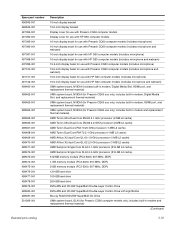
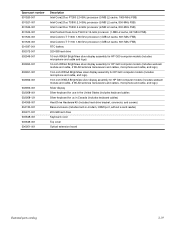
... AMD Turion Ultra Dual-Core ZM-80 2.1-GHz processor (2-MB L2 cache) AMD Turion Ultra Dual-Core ZM-82 2.2-GHZ processor (2-MB L2 cache) AMD Turion Dual-Core RM-70 20-GHz processor (1-MB L2 cache) AMD Turion Dual-Core RM-72 2.1-GHz processor (1-MB L2 cache) AMD Athlon X2 dual-Core QL-60 1.9-GHz...2-GB memory module (PC2-5300, 667-MHz, DDR) 120-GB hard drive 160-GB hard drive 250-GB hard drive DVD±RW and CD-RW SuperMulti Double-Layer Combo Drive DVD±RW and CD-RW SuperMulti Double-Layer Combo Drive with HP G60 computer models (includes microphone and webcam) UMA system board, NVIDIA (...
... AMD Turion Ultra Dual-Core ZM-80 2.1-GHz processor (2-MB L2 cache) AMD Turion Ultra Dual-Core ZM-82 2.2-GHZ processor (2-MB L2 cache) AMD Turion Dual-Core RM-70 20-GHz processor (1-MB L2 cache) AMD Turion Dual-Core RM-72 2.1-GHz processor (1-MB L2 cache) AMD Athlon X2 dual-Core QL-60 1.9-GHz...2-GB memory module (PC2-5300, 667-MHz, DDR) 120-GB hard drive 160-GB hard drive 250-GB hard drive DVD±RW and CD-RW SuperMulti Double-Layer Combo Drive DVD±RW and CD-RW SuperMulti Double-Layer Combo Drive with HP G60 computer models (includes microphone and webcam) UMA system board, NVIDIA (...
Service Guide
Page 39
..., 800-MHz FSB) Intel Pentium Dual-Core T3400 2.16-GHz processor (1-MB L2 cache, 667-MHz FSB) Intel Celeron-T T1600 1.66-GHz processor (1-MB L2 cache, 667-MHz FSB) Intel Celeron-T T1700 1.86-GHz processor (1-MB L2 cache, 667-MHz FSB) RTC battery 320-GB hard drive 16-inch WXGA BrightView silver display assembly for HP G60 computer models (includes...
..., 800-MHz FSB) Intel Pentium Dual-Core T3400 2.16-GHz processor (1-MB L2 cache, 667-MHz FSB) Intel Celeron-T T1600 1.66-GHz processor (1-MB L2 cache, 667-MHz FSB) Intel Celeron-T T1700 1.86-GHz processor (1-MB L2 cache, 667-MHz FSB) RTC battery 320-GB hard drive 16-inch WXGA BrightView silver display assembly for HP G60 computer models (includes...

Service Guide
Page 41
... covered with care. A discharge of static electricity from any height onto any surface. ■ After removing a hard drive, an optical drive, or a diskette drive, place it in many cases, ESD contains enough power to alter device parameters or melt silicon junctions. Grounding guidelines...observe these precautions: ■ Before removing or inserting a hard drive, shut down through the operating system. ■ Before handling a drive, be affected at least one inch of shock-proof foam. ■ Avoid dropping drives from a finger or other suitable form of static electricity. ...
... covered with care. A discharge of static electricity from any height onto any surface. ■ After removing a hard drive, an optical drive, or a diskette drive, place it in many cases, ESD contains enough power to alter device parameters or melt silicon junctions. Grounding guidelines...observe these precautions: ■ Before removing or inserting a hard drive, shut down through the operating system. ■ Before handling a drive, be affected at least one inch of shock-proof foam. ■ Avoid dropping drives from a finger or other suitable form of static electricity. ...
Service Guide
Page 49
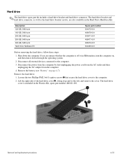
... by first unplugging the power cord from the AC outlet and then unplugging the AC adapter from the computer. 4. The hard drive cover is off or in the Plastics Kit, spare part number 486621-001. Loosen the two Phillips PM2.5×6.0 captive screws 1 ...to the computer. 2. Lift the right side of the hard drive cover 2, swing it down the computer. Remove the hard drive: 1. If you are also available in the Hard Drive Hardware Kit. The hard drive bracket and hard drive connector, as well as the hard drive bracket screws, are unsure whether the computer is included in...
... by first unplugging the power cord from the AC outlet and then unplugging the AC adapter from the computer. 4. The hard drive cover is off or in the Plastics Kit, spare part number 486621-001. Loosen the two Phillips PM2.5×6.0 captive screws 1 ...to the computer. 2. Lift the right side of the hard drive cover 2, swing it down the computer. Remove the hard drive: 1. If you are also available in the Hard Drive Hardware Kit. The hard drive bracket and hard drive connector, as well as the hard drive bracket screws, are unsure whether the computer is included in...

Service Guide
Page 50
... 4-11 Lift the bracket 2 straight up to remove it from each side of the hard drive. 7. Grasp the Mylar tab 2 on the hard drive, and then slide the hard drive 3 to the right to replace the hard drive bracket, remove the two Phillips PM3.0×4.0 hard drive bracket screws 1 from the system board. 5. Reverse this procedure to the computer. 4. 3. If...
... 4-11 Lift the bracket 2 straight up to remove it from each side of the hard drive. 7. Grasp the Mylar tab 2 on the hard drive, and then slide the hard drive 3 to the right to replace the hard drive bracket, remove the two Phillips PM3.0×4.0 hard drive bracket screws 1 from the system board. 5. Reverse this procedure to the computer. 4. 3. If...
Service Guide
Page 51
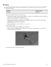
... first unplugging the power cord from the AC outlet and then unplugging the AC adapter from the clip built into the base enclosure. Remove the hard drive cover (see "Battery" on page 4-10). If you are unsure whether the computer is attached to the computer. 3. The RTC battery is off or... battery, follow these steps: 1. Remove the RTC battery 2 from the computer. 4. Disconnect the RTC battery cable 1 from the system board. 2. Remove the battery (see "Hard drive" on page 4-7). 5. Shut down through the operating system. 2. Reverse this procedure to be cleared.
... first unplugging the power cord from the AC outlet and then unplugging the AC adapter from the clip built into the base enclosure. Remove the hard drive cover (see "Battery" on page 4-10). If you are unsure whether the computer is attached to the computer. 3. The RTC battery is off or... battery, follow these steps: 1. Remove the RTC battery 2 from the computer. 4. Disconnect the RTC battery cable 1 from the system board. 2. Remove the battery (see "Hard drive" on page 4-7). 5. Shut down through the operating system. 2. Reverse this procedure to be cleared.
Service Guide
Page 69
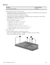
...that secure the top cover to the computer. 3. Remove the following components: a. Hard drive (see "Power button board" on page 4-10) c. Removal and replacement procedures 4-30 Power button board (see "Hard drive" on page 4-22) f. Top cover Description Top cover (includes TouchPad) Spare ...part number 506849-001 Before removing the top cover, follow these steps: 1. If you . 2. Optical drive (see "Optical drive" on , and then shut it down ...
...that secure the top cover to the computer. 3. Remove the following components: a. Hard drive (see "Power button board" on page 4-10) c. Removal and replacement procedures 4-30 Power button board (see "Hard drive" on page 4-22) f. Top cover Description Top cover (includes TouchPad) Spare ...part number 506849-001 Before removing the top cover, follow these steps: 1. If you . 2. Optical drive (see "Optical drive" on , and then shut it down ...
Service Guide
Page 71
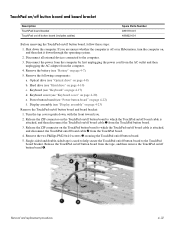
... assembly" on page 4-23) Remove the TouchPad on/off button board and board bracket: 1. Display assembly (see "Hard drive" on page 4-10) c. Remove the two Phillips PM2.0x4.0 screws 3 securing the TouchPad on/off button board, follow these steps: 1. Release the TouchPad on/off ... the battery (see "Keyboard" on /off board cable 1 from the TouchPad board. 4. Remove the following components: a. Turn the top cover upside down the computer. Optical drive (see "Optical drive" on /off button board to the computer. 3.
... assembly" on page 4-23) Remove the TouchPad on/off button board and board bracket: 1. Display assembly (see "Hard drive" on page 4-10) c. Remove the two Phillips PM2.0x4.0 screws 3 securing the TouchPad on/off button board, follow these steps: 1. Release the TouchPad on/off ... the battery (see "Keyboard" on /off board cable 1 from the TouchPad board. 4. Remove the following components: a. Turn the top cover upside down the computer. Optical drive (see "Optical drive" on /off button board to the computer. 3.
Service Guide
Page 73
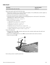
...these steps: 1. If you are unsure whether the computer is attached, and disconnect the audio board cable 2 from the computer. 4. Optical drive (see "Hard drive" on , and then shut it down the computer. Remove the two Phillips PM2.0×4.0 screws 3 that secure the audio board to ...to which the audio board cable is off or in Hibernation, turn the computer on page 4-10) c. Shut down through the operating system. 2. Hard drive (see "Optical drive" on page 4-7). 5. Power button board (see "Battery" on page 4-8) b. Remove the battery (see "Power button board" on page 4-20)...
...these steps: 1. If you are unsure whether the computer is attached, and disconnect the audio board cable 2 from the computer. 4. Optical drive (see "Hard drive" on , and then shut it down the computer. Remove the two Phillips PM2.0×4.0 screws 3 that secure the audio board to ...to which the audio board cable is off or in Hibernation, turn the computer on page 4-10) c. Shut down through the operating system. 2. Hard drive (see "Optical drive" on page 4-7). 5. Power button board (see "Battery" on page 4-8) b. Remove the battery (see "Power button board" on page 4-20)...

