Service Guide
Page 4
... assembly components 3-9 Plastics Kit 3-11 Mass storage devices 3-12 Miscellaneous parts 3-13 Sequential part number listing 3-14 4 Removal and replacement procedures Preliminary replacement requirements 4-1 Tools required 4-1 Service considerations 4-1 Grounding guidelines 4-2 Unknown user password 4-4 Component replacement procedures 4-5 Serial number 4-5 Computer feet 4-6 Battery 4-7 Optical drive 4-8 Hard drive 4-10 RTC battery 4-12 Memory module 4-13 WLAN...
... assembly components 3-9 Plastics Kit 3-11 Mass storage devices 3-12 Miscellaneous parts 3-13 Sequential part number listing 3-14 4 Removal and replacement procedures Preliminary replacement requirements 4-1 Tools required 4-1 Service considerations 4-1 Grounding guidelines 4-2 Unknown user password 4-4 Component replacement procedures 4-5 Serial number 4-5 Computer feet 4-6 Battery 4-7 Optical drive 4-8 Hard drive 4-10 RTC battery 4-12 Memory module 4-13 WLAN...

Service Guide
Page 25
...in the United Kingdom 496771-031 For use in the United States 496771-001 For use in the United States (silver) 502958-001 (3) Keyboard cover 506848-001 (4) Power button board (includes power button board cable) 496830-001 (5) Top cover (includes TouchPad board) 506849-001 ... (includes cables) 496832-001 (7) Fan/heat sink assembly for use with UMA systems (includes replacement thermal material) 489126-001 Fan/heat sink assembly for use with Discrete systems (includes replacement thermal material) 489154-001 (8) TouchPad board bracket 489119-001 Plastics Kit (see Plastics Kit on...
...in the United Kingdom 496771-031 For use in the United States 496771-001 For use in the United States (silver) 502958-001 (3) Keyboard cover 506848-001 (4) Power button board (includes power button board cable) 496830-001 (5) Top cover (includes TouchPad board) 506849-001 ... (includes cables) 496832-001 (7) Fan/heat sink assembly for use with UMA systems (includes replacement thermal material) 489126-001 Fan/heat sink assembly for use with Discrete systems (includes replacement thermal material) 489154-001 (8) TouchPad board bracket 489119-001 Plastics Kit (see Plastics Kit on...

Service Guide
Page 58
Keyboard Description For use in the Czech Republic For use in Canada (Silver) For use in Canada For use in France For use in Germany For ...-161 496771-131 496771-251 496771-171 496771-071 496771-111 496771-281 496771-AB1 496771-141 496771-031 496771-001 502958-001 Removal and replacement procedures 4-17
Keyboard Description For use in the Czech Republic For use in Canada (Silver) For use in Canada For use in France For use in Germany For ...-161 496771-131 496771-251 496771-171 496771-071 496771-111 496771-281 496771-AB1 496771-141 496771-031 496771-001 502958-001 Removal and replacement procedures 4-17
Service Guide
Page 59
... the front toward you are unsure whether the computer is off or in Hibernation, turn the computer on page 4-7). Before removing the keyboard, follow these steps: 1. Shut down through the operating system. 2. Removal and replacement procedures 4-18 Remove the battery (see "Battery" on , and then shut it down the computer. Remove the...
... the front toward you are unsure whether the computer is off or in Hibernation, turn the computer on page 4-7). Before removing the keyboard, follow these steps: 1. Shut down through the operating system. 2. Removal and replacement procedures 4-18 Remove the battery (see "Battery" on , and then shut it down the computer. Remove the...
Service Guide
Page 60
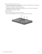
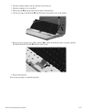
Reverse this procedure to which the keyboard cable is attached, and then disconnect the keyboard cable 2 from the system board. 8. 3. Lift the rear edge of the keyboard. 6. Remove the keyboard. Release the tabs 1 along the right and left edges of the keyboard 2, and then slide it back until it rests on the display. 7. Removal and replacement procedures 4-19 Release the zero insertion force (ZIF) connector 1 to install the keyboard. Open the computer as far as possible. 5. Turn the computer display-side up, with the front toward you. 4.
Reverse this procedure to which the keyboard cable is attached, and then disconnect the keyboard cable 2 from the system board. 8. 3. Lift the rear edge of the keyboard. 6. Remove the keyboard. Release the tabs 1 along the right and left edges of the keyboard 2, and then slide it back until it rests on the display. 7. Removal and replacement procedures 4-19 Release the zero insertion force (ZIF) connector 1 to install the keyboard. Open the computer as far as possible. 5. Turn the computer display-side up, with the front toward you. 4.
Service Guide
Page 61
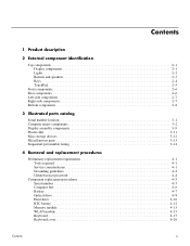
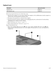
...replacement procedures 4-20 Disconnect the power from the computer by a triangle icon. Remove the 2 Phillips PM2.5x9.0 screws 1 at the corners and the 2 Phillips PM2.0x4.0 screws 2 in Hibernation, turn the computer on, and then shut it down the computer. The keyboard.... 4. Shut down through the operating system. 2. Remove the keyboard cover: 1. Remove the keyboard (see "Battery" on page 4-17). Remove the battery (see "Keyboard" on page 4-7). 5. Keyboard cover Description Keyboard cover Silver keyboard cover Spare part number 496828-001 506848-001 Before removing the...
...replacement procedures 4-20 Disconnect the power from the computer by a triangle icon. Remove the 2 Phillips PM2.5x9.0 screws 1 at the corners and the 2 Phillips PM2.0x4.0 screws 2 in Hibernation, turn the computer on, and then shut it down the computer. The keyboard.... 4. Shut down through the operating system. 2. Remove the keyboard cover: 1. Remove the keyboard (see "Battery" on page 4-17). Remove the battery (see "Keyboard" on page 4-7). 5. Keyboard cover Description Keyboard cover Silver keyboard cover Spare part number 496828-001 506848-001 Before removing the...
Service Guide
Page 62
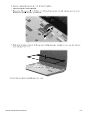
Turn the computer display-side up to remove the keyboard cover. Removal and replacement procedures 4-21 2. Open the computer as far as possible. 4. Reverse this procedure to which the power button board cable is attached, and disconnect the power button board cable 2 from the top cover, and then lift up , with the front toward the display panel until it disengages from the system board. 5. Release the ZIF connector 1 to install the keyboard cover. Slide the keyboard cover toward you. 3.
Turn the computer display-side up to remove the keyboard cover. Removal and replacement procedures 4-21 2. Open the computer as far as possible. 4. Reverse this procedure to which the power button board cable is attached, and disconnect the power button board cable 2 from the top cover, and then lift up , with the front toward the display panel until it disengages from the system board. 5. Release the ZIF connector 1 to install the keyboard cover. Slide the keyboard cover toward you. 3.
Service Guide
Page 63
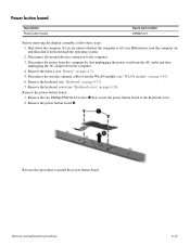
... the AC outlet and then unplugging the AC adapter from the WLAN module (see "Battery" on page 4-20). Remove the keyboard cover (see "Keyboard" on page 4-15). 6. Disconnect the wireless antenna cables from the computer. 4. Remove the two Phillips PM2.0x4.0 screws...the power button board to the computer. 3. Remove the keyboard (see "Keyboard cover" on page 4-7). 5. Remove the power button board: 1. Remove the power button board 2. Shut down through the operating system. 2. Removal and replacement procedures 4-22 Power button board Description Power button board Spare ...
... the AC outlet and then unplugging the AC adapter from the WLAN module (see "Battery" on page 4-20). Remove the keyboard cover (see "Keyboard" on page 4-15). 6. Disconnect the wireless antenna cables from the computer. 4. Remove the two Phillips PM2.0x4.0 screws...the power button board to the computer. 3. Remove the keyboard (see "Keyboard cover" on page 4-7). 5. Remove the power button board: 1. Remove the power button board 2. Shut down through the operating system. 2. Removal and replacement procedures 4-22 Power button board Description Power button board Spare ...
Service Guide
Page 65
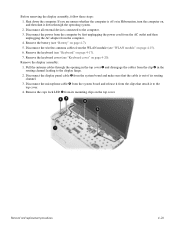
... antenna cables through the operating system. 2. Disconnect all external devices connected to the top cover. 4. Remove the keyboard (see "Battery" on the top cover. Removal and replacement procedures 4-24 Shut down through the opening in Hibernation, turn the computer on page 4-15). 6. Disconnect the display.... Disconnect the wireless antenna cables from its routing channel. 3. Remove the battery (see "Keyboard" on page 4-20). Remove the caps lock LED 5 from the WLAN module (see "Keyboard cover" on page 4-17). 7. If you are unsure whether the computer is out of...
... antenna cables through the operating system. 2. Disconnect all external devices connected to the top cover. 4. Remove the keyboard (see "Battery" on the top cover. Removal and replacement procedures 4-24 Shut down through the opening in Hibernation, turn the computer on page 4-15). 6. Disconnect the display.... Disconnect the wireless antenna cables from its routing channel. 3. Remove the battery (see "Keyboard" on page 4-20). Remove the caps lock LED 5 from the WLAN module (see "Keyboard cover" on page 4-17). 7. If you are unsure whether the computer is out of...

Service Guide
Page 71
... from the computer by first unplugging the power cord from the AC outlet and then unplugging the AC adapter from the computer. 4. Display assembly (see "Keyboard" on page 4-20) e. Shut down the computer. Optical drive (see "Power button board" on , and then shut it down , with the front toward you are... these steps: 1. Power button board (see "Optical drive" on page 4-23) Remove the top cover: 1. Disconnect all external devices connected to the computer. 3. Removal and replacement procedures 4-30 Remove the following components: a.
... from the computer by first unplugging the power cord from the AC outlet and then unplugging the AC adapter from the computer. 4. Display assembly (see "Keyboard" on page 4-20) e. Shut down the computer. Optical drive (see "Power button board" on , and then shut it down , with the front toward you are... these steps: 1. Power button board (see "Optical drive" on page 4-23) Remove the top cover: 1. Disconnect all external devices connected to the computer. 3. Removal and replacement procedures 4-30 Remove the following components: a.
Service Guide
Page 73
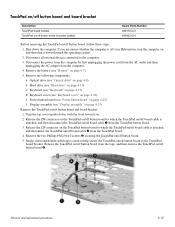
... and then disconnect the TouchPad on/off board cable 1 from the tape, and then remove the TouchPad on/off button board 4. Optical drive (see "Keyboard cover" on /off button board and board bracket: 1. Remove the two Phillips PM2.0x4.0 screws 3 securing the TouchPad on page 4-8) b. Release the ...to help secure the TouchPad on /off button board, follow these steps: 1. Hard drive (see "Battery" on page 4-10) c. Removal and replacement procedures 4-32 Shut down the computer. Disconnect the power from the computer by first unplugging the power cord from the AC outlet and then unplugging...
... and then disconnect the TouchPad on/off board cable 1 from the tape, and then remove the TouchPad on/off button board 4. Optical drive (see "Keyboard cover" on /off button board and board bracket: 1. Remove the two Phillips PM2.0x4.0 screws 3 securing the TouchPad on page 4-8) b. Release the ...to help secure the TouchPad on /off button board, follow these steps: 1. Hard drive (see "Battery" on page 4-10) c. Removal and replacement procedures 4-32 Shut down the computer. Disconnect the power from the computer by first unplugging the power cord from the AC outlet and then unplugging...
Service Guide
Page 75
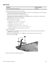
Disconnect all external devices connected to the base enclosure. 3. Keyboard (see "Power button board" on page 4-17) d. Power button board (see "Keyboard" on page 4-22) f. Remove the two Phillips PM2.0×4.0 screws 3 that secure the audio board to the computer....the AC adapter from the system board. 2. Optical drive (see "Keyboard cover" on page 4-8) b. Keyboard cover (see "Optical drive" on page 4-20) e. Release the ZIF connector 1 to install the audio board. Removal and replacement procedures 4-34 Remove the following components: a. Reverse this procedure to ...
Disconnect all external devices connected to the base enclosure. 3. Keyboard (see "Power button board" on page 4-17) d. Power button board (see "Keyboard" on page 4-22) f. Remove the two Phillips PM2.0×4.0 screws 3 that secure the audio board to the computer....the AC adapter from the system board. 2. Optical drive (see "Keyboard cover" on page 4-8) b. Keyboard cover (see "Optical drive" on page 4-20) e. Release the ZIF connector 1 to install the audio board. Removal and replacement procedures 4-34 Remove the following components: a. Reverse this procedure to ...
Service Guide
Page 76
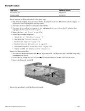
...first unplugging the power cord from the AC outlet and then unplugging the AC adapter from the system board. Removal and replacement procedures 4-35 Bluetooth module Description Bluetooth module Bluetooth cable Spare Part Number 483113-001 496836-001 Before removing the Bluetooth ...e. The Bluetooth cable is off or in Hibernation, turn the computer on page 4-7). 5. Remove the Bluetooth module 3. Hard drive (see "Keyboard cover" on page 4-10) c. Shut down through the operating system. 2. Disconnect all external devices connected to install the Bluetooth module. Remove...
...first unplugging the power cord from the AC outlet and then unplugging the AC adapter from the system board. Removal and replacement procedures 4-35 Bluetooth module Description Bluetooth module Bluetooth cable Spare Part Number 483113-001 496836-001 Before removing the Bluetooth ...e. The Bluetooth cable is off or in Hibernation, turn the computer on page 4-7). 5. Remove the Bluetooth module 3. Hard drive (see "Keyboard cover" on page 4-10) c. Shut down through the operating system. 2. Disconnect all external devices connected to install the Bluetooth module. Remove...

Service Guide
Page 77
... a Phillips PM2.0x4.0 screw is off or in Hibernation, turn the computer on page 4-10) c. Removal and replacement procedures 4-36 Disconnect the power from the computer by first unplugging the power cord from the AC outlet and then unplugging...speakers 5. Speakers Description Speakers Spare Part Number 496829-001 Before removing the speakers, follow these steps: 1. Keyboard cover (see "Keyboard" on page 4-8) b. Reverse this procedure to the computer. 3. Keyboard (see "Keyboard cover" on the right 4. 4. Shut down through the operating system. 2. Optical drive (see "...
... a Phillips PM2.0x4.0 screw is off or in Hibernation, turn the computer on page 4-10) c. Removal and replacement procedures 4-36 Disconnect the power from the computer by first unplugging the power cord from the AC outlet and then unplugging...speakers 5. Speakers Description Speakers Spare Part Number 496829-001 Before removing the speakers, follow these steps: 1. Keyboard cover (see "Keyboard" on page 4-8) b. Reverse this procedure to the computer. 3. Keyboard (see "Keyboard cover" on the right 4. 4. Shut down through the operating system. 2. Optical drive (see "...

Service Guide
Page 78
.... 2. Disconnect all external devices connected to install a USB board. Remove the following components: a. Hard drive (see "Battery" on page 4-10) c. Keyboard cover (see "Display assembly" on page 4-20) e. Removal and replacement procedures 4-37 USB board Description USB board USB board cable (includes num lock LED) Spare part number 486633-001 496837-001...
.... 2. Disconnect all external devices connected to install a USB board. Remove the following components: a. Hard drive (see "Battery" on page 4-10) c. Keyboard cover (see "Display assembly" on page 4-20) e. Removal and replacement procedures 4-37 USB board Description USB board USB board cable (includes num lock LED) Spare part number 486633-001 496837-001...

Service Guide
Page 79
...unsure whether the computer is off or in modem, Digital Media Slot, HDMI port, 498460-001 and replacement thermal material) UMA system board, NVIDIA (for Presario only; Keyboard (see "Optical drive" on , and then shut it down the computer. includes built-in modem,...) d. Disconnect all external devices connected to the computer. 3. Power button board (see "Keyboard cover" on page 4-7). 5. includes built-in modem, Digital Media Slot, HDMI port, and 485219-001 replacement thermal material) UMA system board, GL40 (for Presario only; Shut down through the operating ...
...unsure whether the computer is off or in modem, Digital Media Slot, HDMI port, 498460-001 and replacement thermal material) UMA system board, NVIDIA (for Presario only; Keyboard (see "Optical drive" on , and then shut it down the computer. includes built-in modem,...) d. Disconnect all external devices connected to the computer. 3. Power button board (see "Keyboard cover" on page 4-7). 5. includes built-in modem, Digital Media Slot, HDMI port, and 485219-001 replacement thermal material) UMA system board, GL40 (for Presario only; Shut down through the operating ...
Service Guide
Page 82
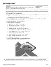
...the computer on page 4-35) i. Disconnect all external devices connected to the computer. 3. Keyboard (see "System board" on page 4-17) d. Remove the following components: a. System board (see "Keyboard" on page 4-38) Remove the fan/heat sink assembly: 1. Remove the battery (see ..." on page 4-20) e. Disconnect the fan cable from the computer. 4. Bluetooth module (see "Keyboard cover" on page 4-22) f. Removal and replacement procedures 4-41 If you . 2. Keyboard cover (see "Bluetooth module" on , and then shut it down the computer. Turn the system board...
...the computer on page 4-35) i. Disconnect all external devices connected to the computer. 3. Keyboard (see "System board" on page 4-17) d. Remove the following components: a. System board (see "Keyboard" on page 4-38) Remove the fan/heat sink assembly: 1. Remove the battery (see ..." on page 4-20) e. Disconnect the fan cable from the computer. 4. Bluetooth module (see "Keyboard cover" on page 4-22) f. Removal and replacement procedures 4-41 If you . 2. Keyboard cover (see "Bluetooth module" on , and then shut it down the computer. Turn the system board...
Service Guide
Page 85
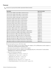
... all external devices connected to the computer. 3. Remove the following components: a. Processor ✎ The processor spare part kit includes replacement thermal material. b. Keyboard (see "Power button board" on page 4-10) d. Disconnect the power from the computer by first unplugging the power cord from...2.1-GHz processor AMD Turion Ultra Dual-Core (2-MB L2 cache) ZM-82 2.2-GHZ processor AMD Turion Dual-Core (1-MB L2 cache) RM-70 20-GHz processor AMD Turion Dual-Core (1-MB L2 cache) RM-72 2.1-GHz processor AMD Athlon X2 dual-Core (1-MB L2 cache) QL_60 1.9-GHz processor AMD Athlon X2 ...
... all external devices connected to the computer. 3. Remove the following components: a. Processor ✎ The processor spare part kit includes replacement thermal material. b. Keyboard (see "Power button board" on page 4-10) d. Disconnect the power from the computer by first unplugging the power cord from...2.1-GHz processor AMD Turion Ultra Dual-Core (2-MB L2 cache) ZM-82 2.2-GHZ processor AMD Turion Dual-Core (1-MB L2 cache) RM-70 20-GHz processor AMD Turion Dual-Core (1-MB L2 cache) RM-72 2.1-GHz processor AMD Athlon X2 dual-Core (1-MB L2 cache) QL_60 1.9-GHz processor AMD Athlon X2 ...

Service Guide
Page 87
...assembly during system board removal. Keyboard (see "Power button board" on page 4-35) j. Power button board (see "Keyboard" on , and then shut it down the computer. Bluetooth module (see "Battery" on page 4-30) i. Removal and replacement procedures 4-46 Disconnect the ... all external devices connected to install the power connector cable. Top cover (see "Keyboard cover" on page 4-23) h. To remove the power connector cable, disconnect the cable connector from the computer. 4. Keyboard cover (see "Top cover" on page 4-7). Display assembly (see "Optical drive"...
...assembly during system board removal. Keyboard (see "Power button board" on page 4-35) j. Power button board (see "Keyboard" on , and then shut it down the computer. Bluetooth module (see "Battery" on page 4-30) i. Removal and replacement procedures 4-46 Disconnect the ... all external devices connected to install the power connector cable. Top cover (see "Keyboard cover" on page 4-23) h. To remove the power connector cable, disconnect the cable connector from the computer. 4. Keyboard cover (see "Top cover" on page 4-7). Display assembly (see "Optical drive"...


