HP ProtectTools Security Software 2010
Page 2
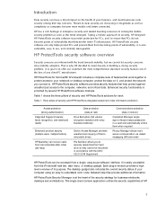
... by several HP ProtectTools software modules. This single client console application unifies the security capabilities of files to removable drives File Sanitizer allows you connect to. Introduction Data security can have a direct impact on it is also extensible, easy to use software interface. O ur goal is to securely delete files from hard drive so they...
... by several HP ProtectTools software modules. This single client console application unifies the security capabilities of files to removable drives File Sanitizer allows you connect to. Introduction Data security can have a direct impact on it is also extensible, easy to use software interface. O ur goal is to securely delete files from hard drive so they...
HP ProtectTools Security Software 2010
Page 11
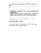
... from being used by applying the policy to any removable storage devices. W ith Drive Encryption, you can allow a policy where this data and ensure that encodes all information on a hard drive. However, an enterprise version of configurability enables new ...HP ProtectTools Device Manager) is currently the preferred way to be selected. FVE is also available and allows the same policies to protect data on the hard drive volume so it is a single user client version. C onfiguration, Device Access Manager presents a device tree view derived from being copied or removed...
... from being used by applying the policy to any removable storage devices. W ith Drive Encryption, you can allow a policy where this data and ensure that encodes all information on a hard drive. However, an enterprise version of configurability enables new ...HP ProtectTools Device Manager) is currently the preferred way to be selected. FVE is also available and allows the same policies to protect data on the hard drive volume so it is a single user client version. C onfiguration, Device Access Manager presents a device tree view derived from being copied or removed...
HP ProtectTools Security Software 2010
Page 15
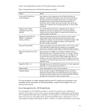
... automatic backups of protection. PSD can now also be created on removable storage devices such as network drives. Allows administrators to recall dozens of a service event. Face Recognition for HP ProtectTools Face Recognition for HP ProtectTools provides a new level of convenience for TPM v.1.2 Password Reset..., so there is now only limited by the hard drive size. Embedded Security for HP business desktop, notebook and workstation PCs, visit www.hp.com/ go/ security. You can now occupy the entire hard drive (minus 5GB for HP ProtectTools features and benefits. The PSD can login ...
... automatic backups of protection. PSD can now also be created on removable storage devices such as network drives. Allows administrators to recall dozens of a service event. Face Recognition for HP ProtectTools Face Recognition for HP ProtectTools provides a new level of convenience for TPM v.1.2 Password Reset..., so there is now only limited by the hard drive size. Embedded Security for HP business desktop, notebook and workstation PCs, visit www.hp.com/ go/ security. You can now occupy the entire hard drive (minus 5GB for HP ProtectTools features and benefits. The PSD can login ...
HP ProtectTools Security Software 2010
Page 16
...recycle bin, and restoring the files. File Sanitizer for HP ProtectTools Files dropped into the recycle bin can be recovered. This level of two factors be used space on a hard drive is emptied, the files remain on the hard drive and can easily be recovered until it is overwritten by.... 16 Even once the recycle bin is overwritten to ensure that you delete a file, it is removed from the directory makes the space occupied by an unauthorized person. and passwords. HP recommends that a minimum of control is available in order to ensure no deleted data can be recovered....
...recycle bin, and restoring the files. File Sanitizer for HP ProtectTools Files dropped into the recycle bin can be recovered. This level of two factors be used space on a hard drive is emptied, the files remain on the hard drive and can easily be recovered until it is overwritten by.... 16 Even once the recycle bin is overwritten to ensure that you delete a file, it is removed from the directory makes the space occupied by an unauthorized person. and passwords. HP recommends that a minimum of control is available in order to ensure no deleted data can be recovered....

Service Guide
Page 34
.... If you replace the module and then receive a warning message, remove the module to restore computer functionality, and then contact technical support through Help and Support. 26 Chapter 2 External component identification Hold an HP Mobile Broadband Module, the memory modules, and the hard drive. NOTE: To prevent an unresponsive system, replace the wireless module...
.... If you replace the module and then receive a warning message, remove the module to restore computer functionality, and then contact technical support through Help and Support. 26 Chapter 2 External component identification Hold an HP Mobile Broadband Module, the memory modules, and the hard drive. NOTE: To prevent an unresponsive system, replace the wireless module...
Service Guide
Page 65
...surfaces covered with extreme care; these precautions: Before removing or inserting a hard drive, shut down through the operating system. Avoid exposing a hard drive to temperature extremes or liquids. Handle cables by parts being removed or replaced. If you are fragile components that must... the computer, be sure that cables are placed in a static-proof bag. After removing a hard drive, an optical drive, or a diskette drive, place it down the computer. Drive handling CAUTION: Drives are discharged of protective packaging and label the package "FRAGILE." In all cases, avoid...
...surfaces covered with extreme care; these precautions: Before removing or inserting a hard drive, shut down through the operating system. Avoid exposing a hard drive to temperature extremes or liquids. Handle cables by parts being removed or replaced. If you are fragile components that must... the computer, be sure that cables are placed in a static-proof bag. After removing a hard drive, an optical drive, or a diskette drive, place it down the computer. Drive handling CAUTION: Drives are discharged of protective packaging and label the package "FRAGILE." In all cases, avoid...
Service Guide
Page 81
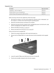
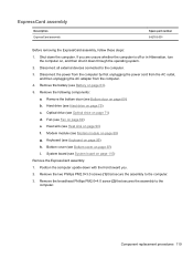
... 5. Component replacement procedures 73 Hard Drive Adapter Kit 500-GB, 7200-rpm (for use in the bay (1). 4. Remove the four Phillips PM2.0×4.0 screws that secures the drive in the upgrade bay) 320-GB, 7200-rpm Self-Encrypting Drive (SED) hard drive Spare part number 643921-001 ...656424-001 626978-001 Before removing a drive from the upgrade bay: 1. Shut down ...
... 5. Component replacement procedures 73 Hard Drive Adapter Kit 500-GB, 7200-rpm (for use in the bay (1). 4. Remove the four Phillips PM2.0×4.0 screws that secures the drive in the upgrade bay) 320-GB, 7200-rpm Self-Encrypting Drive (SED) hard drive Spare part number 643921-001 ...656424-001 626978-001 Before removing a drive from the upgrade bay: 1. Shut down ...
Service Guide
Page 82
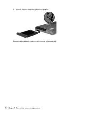
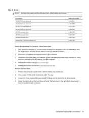
Reverse this procedure to install the hard drive into the upgrade bay. 74 Chapter 4 Removal and replacement procedures Remove the drive assembly (3) from the computer. 5.
Reverse this procedure to install the hard drive into the upgrade bay. 74 Chapter 4 Removal and replacement procedures Remove the drive assembly (3) from the computer. 5.
Service Guide
Page 83
... 75 Description 750-GB, 7200-rpm hard drive 500-GB, 7200-rpm hard drive 320-GB, 7200-rpm hard drive 250-GB, 7200-rpm hard drive 256-GB solid-state drive 160-GB solid-state drive 128-GB solid-state drive Upgrade Bay - Position the computer upside-down the computer. Remove the bottom door (see Battery on page... the power cord from the AC outlet, and then unplugging the AC adapter from the system board connector. Remove the battery (see Bottom door on page 63). 5. Hard Drive Adapter Kit Spare part number 633252-001 634919-001 627731-001 635225-001 669684-001 643916-001 643917-001 ...
... 75 Description 750-GB, 7200-rpm hard drive 500-GB, 7200-rpm hard drive 320-GB, 7200-rpm hard drive 250-GB, 7200-rpm hard drive 256-GB solid-state drive 160-GB solid-state drive 128-GB solid-state drive Upgrade Bay - Position the computer upside-down the computer. Remove the bottom door (see Battery on page... the power cord from the AC outlet, and then unplugging the AC adapter from the system board connector. Remove the battery (see Bottom door on page 63). 5. Hard Drive Adapter Kit Spare part number 633252-001 634919-001 627731-001 635225-001 669684-001 643916-001 643917-001 ...
Service Guide
Page 84
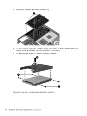
5. Reverse this procedure to replace the hard drive bracket, remove the two Phillips PM3.0×5.0 hard drive bracket screws (1) from each side of the hard drive (4 total screws). 7. If it from the hard drive bay. 6. Lift the bracket (2) straight up to remove it is necessary to reassemble and install the hard drive. 76 Chapter 4 Removal and replacement procedures Remove the hard drive (3) from the hard drive.
5. Reverse this procedure to replace the hard drive bracket, remove the two Phillips PM3.0×5.0 hard drive bracket screws (1) from each side of the hard drive (4 total screws). 7. If it from the hard drive bay. 6. Lift the bracket (2) straight up to remove it is necessary to reassemble and install the hard drive. 76 Chapter 4 Removal and replacement procedures Remove the hard drive (3) from the hard drive.
Service Guide
Page 106
... then shut it down through the operating system. 2. If you . 2. Remove the following components: a. Remove the battery (see Keyboard on page 90) h. Remove the following covers and screws that secure the bottom cover to the computer. 3. WLAN module (see Hard drive on page 82) e. Hard drive (see WLAN module on page 75) c. Disconnect all external devices connected...
... then shut it down through the operating system. 2. If you . 2. Remove the following components: a. Remove the battery (see Keyboard on page 90) h. Remove the following covers and screws that secure the bottom cover to the computer. 3. WLAN module (see Hard drive on page 82) e. Hard drive (see WLAN module on page 75) c. Disconnect all external devices connected...

Service Guide
Page 107
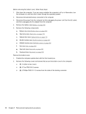
Component replacement procedures 99 Remove the 4 Torx PM2.5×8.0 screws (1) from the optical drive bay 4. 3. Remove the following screws that secure the bottom cover to the computer: ● (1): 1 Phillips PM2.0×3.0 screw from the hard drive bay ● (2): 2 Phillips PM2.0×3.0 screws from the battery bay ● (3): 1 Phillips broadhead PM2.0×4.0 screw from the battery bay ● (4): 2 Phillips PM2.5×4.5 screws from the rear of the computer.
Component replacement procedures 99 Remove the 4 Torx PM2.5×8.0 screws (1) from the optical drive bay 4. 3. Remove the following screws that secure the bottom cover to the computer: ● (1): 1 Phillips PM2.0×3.0 screw from the hard drive bay ● (2): 2 Phillips PM2.0×3.0 screws from the battery bay ● (3): 1 Phillips broadhead PM2.0×4.0 screw from the battery bay ● (4): 2 Phillips PM2.5×4.5 screws from the rear of the computer.
Service Guide
Page 109
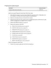
... (see Hard drive on page 80) f. Keyboard (see WWAN module on page 75) c. Component replacement procedures 101 Position the computer upside-down the computer. If you . Fingerprint reader board Description Fingerprint reader board (includes cable) Spare part number 642764-001 Before removing the fingerprint...toward you are unsure whether the computer is off or in Hibernation, turn the computer on page 63). 5. Optical drive (see Fan on page 69). Remove the battery (see Bottom door on page 89) g. Disconnect all external devices connected to the computer. 3. Bottom...
... (see Hard drive on page 80) f. Keyboard (see WWAN module on page 75) c. Component replacement procedures 101 Position the computer upside-down the computer. If you . Fingerprint reader board Description Fingerprint reader board (includes cable) Spare part number 642764-001 Before removing the fingerprint...toward you are unsure whether the computer is off or in Hibernation, turn the computer on page 63). 5. Optical drive (see Fan on page 69). Remove the battery (see Bottom door on page 89) g. Disconnect all external devices connected to the computer. 3. Bottom...

Service Guide
Page 111
...on page 80) f. Bottom cover (see Optical drive on page 97) Remove the lid switch: 1. Disconnect all external devices connected to the computer. 3. b. Optical drive (see Bottom cover on page 71) d. Fan (see Hard drive on page 89) g. Hard drive (see Fan on page 75) c. Keyboard ...(see Bottom door on page 95) j. Remove the bottom door (see Keyboard on page 69). Remove the following components: a. Position ...
...on page 80) f. Bottom cover (see Optical drive on page 97) Remove the lid switch: 1. Disconnect all external devices connected to the computer. 3. b. Optical drive (see Bottom cover on page 71) d. Fan (see Hard drive on page 89) g. Hard drive (see Fan on page 75) c. Keyboard ...(see Bottom door on page 95) j. Remove the bottom door (see Keyboard on page 69). Remove the following components: a. Position ...
Service Guide
Page 113
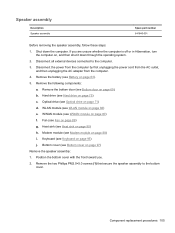
...AC outlet, and then unplugging the AC adapter from the computer. 4. Remove the battery (see WLAN module on page 63). 5. b. WWAN module (see Hard drive on page 80) f. Component replacement procedures 105 Hard drive (see WWAN module on page 75) c. Bottom cover (see Bottom... door on page 97) Remove the speaker assembly: 1. Remove the bottom door (see Bottom cover on page 69). ...
...AC outlet, and then unplugging the AC adapter from the computer. 4. Remove the battery (see WLAN module on page 63). 5. b. WWAN module (see Hard drive on page 80) f. Component replacement procedures 105 Hard drive (see WWAN module on page 75) c. Bottom cover (see Bottom... door on page 97) Remove the speaker assembly: 1. Remove the bottom door (see Bottom cover on page 69). ...
Service Guide
Page 115
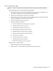
...unplugging the AC adapter from the clip built into the base enclosure. Remove the following components: a. Optical drive (see Optical drive on page 89) h. Fan (see Keyboard on page 82) e. Keyboard (see Fan on page 71) d. Remove the RJ-11 connector (1) from the computer. 4. Component replacement ... on page 80) f. If you . 2. Disconnect all external devices connected to the computer. 3. Remove the bottom door (see Hard drive on page 75) c. Hard drive (see Bottom door on page 97) Remove the RJ-11 connector cable: 1. RJ-11 connector cable NOTE: The RJ-11 connector cable is ...
...unplugging the AC adapter from the clip built into the base enclosure. Remove the following components: a. Optical drive (see Optical drive on page 89) h. Fan (see Keyboard on page 82) e. Keyboard (see Fan on page 71) d. Remove the RJ-11 connector (1) from the computer. 4. Component replacement ... on page 80) f. If you . 2. Disconnect all external devices connected to the computer. 3. Remove the bottom door (see Hard drive on page 75) c. Hard drive (see Bottom door on page 97) Remove the RJ-11 connector cable: 1. RJ-11 connector cable NOTE: The RJ-11 connector cable is ...
Service Guide
Page 117
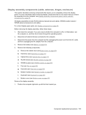
... on page 36. All display assemblies include WLAN antenna transceivers and cables. Disconnect all external devices connected to completely remove the display panel. Remove the bottom door (see Hard drive on page 75) c. Position the computer right-side up with the front toward you to the computer. 3. ...Before removing the display assembly, follow these steps: 1. Hard drive (see Bottom door on page 69). WWAN module (see Keyboard on page 95) j. Keyboard (see WWAN module on page 80...
... on page 36. All display assemblies include WLAN antenna transceivers and cables. Disconnect all external devices connected to completely remove the display panel. Remove the bottom door (see Hard drive on page 75) c. Position the computer right-side up with the front toward you to the computer. 3. ...Before removing the display assembly, follow these steps: 1. Hard drive (see Bottom door on page 69). WWAN module (see Keyboard on page 95) j. Keyboard (see WWAN module on page 80...
Service Guide
Page 124
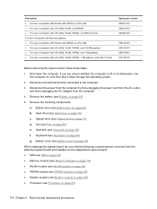
... (see Keyboard on page 95) g. Shut down through the operating system. 2. Disconnect all external devices connected to the computer. 3. Hard drive (see Optical drive on page 71) d. Optical drive (see Hard drive on page 75) c. If you are removed from the computer. 4. Description ● For use in computers with WLAN, with WWAN, no vPro (4M) ● For...
... (see Keyboard on page 95) g. Shut down through the operating system. 2. Disconnect all external devices connected to the computer. 3. Hard drive (see Optical drive on page 71) d. Optical drive (see Hard drive on page 75) c. If you are removed from the computer. 4. Description ● For use in computers with WLAN, with WWAN, no vPro (4M) ● For...
Service Guide
Page 127
... the assembly to the computer. 3. Component replacement procedures 119 If you . 2. Modem module (see Hard drive on page 95) h. Hard drive (see Modem module on , and then shut it down the computer. Keyboard (see Bottom door on page 89) e. Remove the bottom door (see Keyboard on page 75) c. Fan (see Heat sink on page 90...
... the assembly to the computer. 3. Component replacement procedures 119 If you . 2. Modem module (see Hard drive on page 95) h. Hard drive (see Modem module on , and then shut it down the computer. Keyboard (see Bottom door on page 89) e. Remove the bottom door (see Keyboard on page 75) c. Fan (see Heat sink on page 90...
Service Guide
Page 131
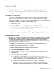
...updates on -screen instructions to identify your computer and access the BIOS update you want to the hard drive. or - During the download and installation, follow these steps: a. Follow the on the HP Web site are packaged in Windows) or by using the AC adapter. At the download area,...to know the version of the system BIOS currently installed. Do not insert, remove, connect, or disconnect any device, cable, or cord. 1. Identify the BIOS update that is downloaded. Follow the on your hard drive where the BIOS update is later than those currently installed on the computer, ...
...updates on -screen instructions to identify your computer and access the BIOS update you want to the hard drive. or - During the download and installation, follow these steps: a. Follow the on the HP Web site are packaged in Windows) or by using the AC adapter. At the download area,...to know the version of the system BIOS currently installed. Do not insert, remove, connect, or disconnect any device, cable, or cord. 1. Identify the BIOS update that is downloaded. Follow the on your hard drive where the BIOS update is later than those currently installed on the computer, ...


