User Manual
Page 1
HP LP1965 19", LP2065 20", and LP2465 24" LCD Monitors User Guide
HP LP1965 19", LP2065 20", and LP2465 24" LCD Monitors User Guide

User Manual
Page 3
NOTE Text set off in this manner indicates that failure to equipment or loss of life. ENWW iii CAUTION Text set off in this manner indicates that failure to follow directions could result in damage to follow directions could result in bodily harm or loss of information. Text set off in this manner provides important supplemental information. About This Guide This guide provides information on setting up the monitor, installing drivers, using the on-screen display menu, troubleshooting and technical specifications. WARNING!
NOTE Text set off in this manner indicates that failure to equipment or loss of life. ENWW iii CAUTION Text set off in this manner indicates that failure to follow directions could result in damage to follow directions could result in bodily harm or loss of information. Text set off in this manner provides important supplemental information. About This Guide This guide provides information on setting up the monitor, installing drivers, using the on-screen display menu, troubleshooting and technical specifications. WARNING!
User Manual
Page 5
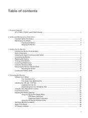
Table of contents 1 Product Features HP LP1965, LP2065, and LP2465 Models 1 2 Safety and Maintenance Guidelines Important Safety Information ...3 Maintenance Guidelines ...4 Cleaning the Monitor ...4 Shipping the Monitor ...4 3 Setting Up the Monitor Installing the Monitor Pedestal Base ...5 Rear Components ...6 Selecting the Signal Connectors and Cables 7 Connecting the Monitor ...8 Adjusting the Monitor ...10 Turning on the Monitor ...12 Connecting USB Devices ...13...
Table of contents 1 Product Features HP LP1965, LP2065, and LP2465 Models 1 2 Safety and Maintenance Guidelines Important Safety Information ...3 Maintenance Guidelines ...4 Cleaning the Monitor ...4 Shipping the Monitor ...4 3 Setting Up the Monitor Installing the Monitor Pedestal Base ...5 Rear Components ...6 Selecting the Signal Connectors and Cables 7 Connecting the Monitor ...8 Adjusting the Monitor ...10 Turning on the Monitor ...12 Connecting USB Devices ...13...

User Manual
Page 6
Installing the HP Display LiteSaver Software 30 sRGB Support ...31 Changing the Color Temperature 31 Installing the sRGB ICM File for Microsoft Windows 2000 and Windows XP 32 ... Materials Disposal ...46 Disposal of Waste Equipment by Users in Private Household in the European Union ..... 46 Restriction of Hazardous Substances (RoHS 46 Appendix D LCD Monitor Quality and Pixel Policy vi ENWW
Installing the HP Display LiteSaver Software 30 sRGB Support ...31 Changing the Color Temperature 31 Installing the sRGB ICM File for Microsoft Windows 2000 and Windows XP 32 ... Materials Disposal ...46 Disposal of Waste Equipment by Users in Private Household in the European Union ..... 46 Restriction of Hazardous Substances (RoHS 46 Appendix D LCD Monitor Quality and Pixel Policy vi ENWW
User Manual
Page 7
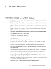
...connects to USB devices) ports ● USB cable included to connect the monitor's USB hub to the USB connector on the computer ● Accessory rail on monitor to accept optional mounted devices, such as an HP speaker bar ● Plug and play capability if supported by the system..., German, Italian, Japanese, and Spanish for ease of setup and screen optimization ● Software and documentation CD that includes HP Display Assistant, Pivot Pro software, monitor driver software, and product documentation ● Energy saver feature to meet requirements for reduced power consumption ENWW...
...connects to USB devices) ports ● USB cable included to connect the monitor's USB hub to the USB connector on the computer ● Accessory rail on monitor to accept optional mounted devices, such as an HP speaker bar ● Plug and play capability if supported by the system..., German, Italian, Japanese, and Spanish for ease of setup and screen optimization ● Software and documentation CD that includes HP Display Assistant, Pivot Pro software, monitor driver software, and product documentation ● Energy saver feature to meet requirements for reduced power consumption ENWW...
User Manual
Page 9
...Requirements section in a grounded (earth) outlet that no one is included with the monitor. For your safety, do not place anything on or trip over them so that is easily accessible at http://www.hp.com/ergo and/or on the Web at all times. • Disconnect power from... manufacturer offers a Damage Replacement Policy so you can replace the equipment, if surge protection fails. The grounding plug is used, use with the monitor, refer to the equipment: • Do not disable the power cord grounding feature. Not all power cords for the computer and its peripheral devices...
...Requirements section in a grounded (earth) outlet that no one is included with the monitor. For your safety, do not place anything on or trip over them so that is easily accessible at http://www.hp.com/ergo and/or on the Web at all times. • Disconnect power from... manufacturer offers a Damage Replacement Policy so you can replace the equipment, if surge protection fails. The grounding plug is used, use with the monitor, refer to the equipment: • Do not disable the power cord grounding feature. Not all power cords for the computer and its peripheral devices...

User Manual
Page 10
...the rating of the cord. These chemicals may need it from the wall outlet. 3. If the monitor is not operating properly or has been dropped or damaged, contact an authorized HP dealer, reseller, or service provider. ● Use only a power source and connection appropriate for ...ventilation. You may damage the cabinet finish as well as indicated on the cord. ● Keep the monitor in use. Disconnect the monitor by grasping the plug...
...the rating of the cord. These chemicals may need it from the wall outlet. 3. If the monitor is not operating properly or has been dropped or damaged, contact an authorized HP dealer, reseller, or service provider. ● Use only a power source and connection appropriate for ...ventilation. You may damage the cabinet finish as well as indicated on the cord. ● Keep the monitor in use. Disconnect the monitor by grasping the plug...

User Manual
Page 11
... the liquid crystals. The master power switch turns off all power to the monitor, computer system, and other mounting fixture; If this chapter. 1. Using both hands, position the monitor over the pedestal base. ENWW Installing the Monitor Pedestal Base 5 When the base locks, it will not recover to lock... the pedestal base in the off position. 3 Setting Up the Monitor To set up the monitor, ensure that the power is turned off to the monitor. NOTE Be sure the master power switch, located on the monitor to its normal condition. 2. Press down firmly on the rear panel ...
... the liquid crystals. The master power switch turns off all power to the monitor, computer system, and other mounting fixture; If this chapter. 1. Using both hands, position the monitor over the pedestal base. ENWW Installing the Monitor Pedestal Base 5 When the base locks, it will not recover to lock... the pedestal base in the off position. 3 Setting Up the Monitor To set up the monitor, ensure that the power is turned off to the monitor. NOTE Be sure the master power switch, located on the monitor to its normal condition. 2. Press down firmly on the rear panel ...

User Manual
Page 12
... DVI-I Connectors USB Upstream Connector Provides slot for use with cable security locks. Connects the AC power cord to the monitor. Connects optional USB devices to the monitor. 6 Chapter 3 Setting Up the Monitor ENWW Rear Components Figure 3-2 Rear Components Component 1 2 3 4 5 6 7 Function Cable Lock Provision Master Power Switch AC Power Connector DVI-I to VGA...
... DVI-I Connectors USB Upstream Connector Provides slot for use with cable security locks. Connects the AC power cord to the monitor. Connects optional USB devices to the monitor. 6 Chapter 3 Setting Up the Monitor ENWW Rear Components Figure 3-2 Rear Components Component 1 2 3 4 5 6 7 Function Cable Lock Provision Master Power Switch AC Power Connector DVI-I to VGA...

User Manual
Page 13
...the DVI-D Signal Cable ENWW Selecting the Signal Connectors and Cables 7 Figure 3-3 Connecting the DVI-I connector on the monitor and the other end to the DVI connector on the front panel. The monitor will automatically determine which inputs have valid video signals. Connect the DVI-D signal cable to a DVI-I connector on... the monitor and the other end to the VGA connector on the computer. The video mode supported by the DVI-I connector is determined by pressing the...
...the DVI-D Signal Cable ENWW Selecting the Signal Connectors and Cables 7 Figure 3-3 Connecting the DVI-I connector on the monitor and the other end to the DVI connector on the front panel. The monitor will automatically determine which inputs have valid video signals. Connect the DVI-D signal cable to a DVI-I connector on... the monitor and the other end to the VGA connector on the computer. The video mode supported by the DVI-I connector is determined by pressing the...

User Manual
Page 14
Connect one may accidentally step on power cords or cables. Do not pull on the monitor. When unplugging from the electrical outlet. Place the monitor in a convenient, well-ventilated location near the computer. 2. The grounding plug is an important safety feature. • Plug the power cord into a grounded (earthed) ...• Disconnect power from the equipment by unplugging the power cord from the electrical outlet, grasp the cord by the plug. 8 Chapter 3 Setting Up the Monitor ENWW Connecting the Monitor 1. Figure 3-5 Connecting the USB Cable WARNING! Arrange them .
Connect one may accidentally step on power cords or cables. Do not pull on the monitor. When unplugging from the electrical outlet. Place the monitor in a convenient, well-ventilated location near the computer. 2. The grounding plug is an important safety feature. • Plug the power cord into a grounded (earthed) ...• Disconnect power from the equipment by unplugging the power cord from the electrical outlet, grasp the cord by the plug. 8 Chapter 3 Setting Up the Monitor ENWW Connecting the Monitor 1. Figure 3-5 Connecting the USB Cable WARNING! Arrange them .

User Manual
Page 15
Connect one end of the power cable to the AC power connector on the back of the monitor, and the other end to an electrical wall outlet. Place the cables through the cable management channel on the back of the monitor base. Figure 3-7 Using the Cable Management Feature ENWW Connecting the Monitor 9 Figure 3-6 Connecting the Power Cable 4. 3.
Connect one end of the power cable to the AC power connector on the back of the monitor, and the other end to an electrical wall outlet. Place the cables through the cable management channel on the back of the monitor base. Figure 3-7 Using the Cable Management Feature ENWW Connecting the Monitor 9 Figure 3-6 Connecting the Power Cable 4. 3.

User Manual
Page 16
Figure 3-9 Swiveling the Monitor 10 Chapter 3 Setting Up the Monitor ENWW Adjusting the Monitor 1. Tilt the monitor's panel forward or backward to set it to +25 degrees. 2. Figure 3-8 Tilting the Monitor NOTE The 24" model has a tilt range of -5 to a comfortable eye level. Swivel the monitor to the left or right for the best viewing angle.
Figure 3-9 Swiveling the Monitor 10 Chapter 3 Setting Up the Monitor ENWW Adjusting the Monitor 1. Tilt the monitor's panel forward or backward to set it to +25 degrees. 2. Figure 3-8 Tilting the Monitor NOTE The 24" model has a tilt range of -5 to a comfortable eye level. Swivel the monitor to the left or right for the best viewing angle.

User Manual
Page 17
...to your eye height for a comfortable viewing position. Gently push down /release button on a stable surface. Guide the display head up when the monitor is parallel to the desired height. 3. c. While pushing down the display head, press the lock-down on the front of the column prevents ...the display head of 100 mm. d. ENWW Adjusting the Monitor 11 A lock-down/release button on the display head. Adjust the monitor's height so that the monitor is locked in the lowest height position: a. WARNING! b.
...to your eye height for a comfortable viewing position. Gently push down /release button on a stable surface. Guide the display head up when the monitor is parallel to the desired height. 3. c. While pushing down the display head, press the lock-down on the front of the column prevents ...the display head of 100 mm. d. ENWW Adjusting the Monitor 11 A lock-down/release button on the display head. Adjust the monitor's height so that the monitor is locked in the lowest height position: a. WARNING! b.

User Manual
Page 18
...screens. * A prolonged period of time is not in use . 12 Chapter 3 Setting Up the Monitor ENWW CAUTION Burn-in image damage may occur on monitors that may occur on the rear of the monitor. 4. Press the power button on the computer. 2. Image retention is a condition that display the ... Press the power switch to your application. Figure 3-11 Pivoting the Monitor NOTE The 20" model (shown above) pivots counter-clockwise; Pivot the monitor from landscape to portrait orientation viewing to adapt to turn off the monitor when it is 12 consecutive hours of non-use for a prolonged ...
...screens. * A prolonged period of time is not in use . 12 Chapter 3 Setting Up the Monitor ENWW CAUTION Burn-in image damage may occur on monitors that may occur on the rear of the monitor. 4. Press the power button on the computer. 2. Image retention is a condition that display the ... Press the power switch to your application. Figure 3-11 Pivoting the Monitor NOTE The 20" model (shown above) pivots counter-clockwise; Pivot the monitor from landscape to portrait orientation viewing to adapt to turn off the monitor when it is 12 consecutive hours of non-use for a prolonged ...

User Manual
Page 19
Connecting USB Devices The monitor provides four USB connectors, two on the side panel and two on the monitor. Refer to connect devices such as a digital camera, USB keyboard, or USB mouse. NOTE You must connect the USB hub cable from the monitor to the computer to enable the USB 2.0 ports on the rear panel, used to Step 2 in Connecting the Monitor. Figure 3-12 Connecting USB Devices ENWW Connecting USB Devices 13
Connecting USB Devices The monitor provides four USB connectors, two on the side panel and two on the monitor. Refer to connect devices such as a digital camera, USB keyboard, or USB mouse. NOTE You must connect the USB hub cable from the monitor to the computer to enable the USB 2.0 ports on the rear panel, used to Step 2 in Connecting the Monitor. Figure 3-12 Connecting USB Devices ENWW Connecting USB Devices 13

User Manual
Page 20
...power cables from the pedestal base to mount the panel on the pedestal base to the LCD. CAUTION Before beginning to disassemble the monitor, be used to mount optional devices, such as the HP speaker bar, to attach to the side (either right or left). 14 Chapter 3 Setting Up the... Monitor ENWW If the monitor has a connected audio cable, disconnect it. 1. Refer to the pedestal base. Using the Accessory Rails The monitor features accessory rails on the rear ...
...power cables from the pedestal base to mount the panel on the pedestal base to the LCD. CAUTION Before beginning to disassemble the monitor, be used to mount optional devices, such as the HP speaker bar, to attach to the side (either right or left). 14 Chapter 3 Setting Up the... Monitor ENWW If the monitor has a connected audio cable, disconnect it. 1. Refer to the pedestal base. Using the Accessory Rails The monitor features accessory rails on the rear ...

User Manual
Page 21
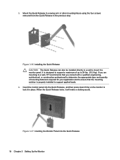
... the Pedestal Base Mounting the Monitor The HP Quick Release can be used because they may damage the monitor. Remove the Quick Release from the Pedestal Base ENWW Removing the Monitor Pedestal Base 15 It allows you to quickly and securely attach the monitor panel to the monitor, four 4 mm, 0.7 ... long screws are required (not provided with the monitor). To attach a third-party mounting solution to the mounting fixture. 1. Figure 3-15 Removing the HP Quick Release from the pedestal base by removing the four screws. Remove the monitor panel from the base. It is important to verify...
... the Pedestal Base Mounting the Monitor The HP Quick Release can be used because they may damage the monitor. Remove the Quick Release from the Pedestal Base ENWW Removing the Monitor Pedestal Base 15 It allows you to quickly and securely attach the monitor panel to the monitor, four 4 mm, 0.7 ... long screws are required (not provided with the monitor). To attach a third-party mounting solution to the mounting fixture. 1. Figure 3-15 Removing the HP Quick Release from the pedestal base by removing the four screws. Remove the monitor panel from the base. It is important to verify...
User Manual
Page 22
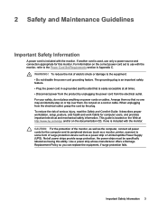
... into the Quick Release, and then press down firmly on the monitor to a swing arm or other mounting fixture using the four screws removed from the Quick Release in place. If you are mounting to a wall, HP recommends that you consult with a qualified engineering, architectural, or construction professional to determine the appropriate...
... into the Quick Release, and then press down firmly on the monitor to a swing arm or other mounting fixture using the four screws removed from the Quick Release in place. If you are mounting to a wall, HP recommends that you consult with a qualified engineering, architectural, or construction professional to determine the appropriate...

User Manual
Page 23
Locating the Rating Labels The rating labels on the rear panel of the monitor display head. Figure 3-18 Locating the Rating Labels ENWW Locating the Rating Labels 17 The rating labels are located on the monitor provide the spare part number, product number, and serial number. You may need these numbers when contacting HP about the monitor model.
Locating the Rating Labels The rating labels on the rear panel of the monitor display head. Figure 3-18 Locating the Rating Labels ENWW Locating the Rating Labels 17 The rating labels are located on the monitor provide the spare part number, product number, and serial number. You may need these numbers when contacting HP about the monitor model.


