
Service Guide
Page 3
... directly on a hard, flat surface. Use the computer only on your lap or obstruct the computer air vents. The computer and the AC adapter comply with the user-accessible surface temperature limits defined by the International Standard for Safety of overheating the computer, do not allow another hard ... during operation. iii To reduce the possibility of heat-related injuries or of Information Technology Equipment (IEC 60950). Do not allow the AC adapter to contact the skin or a soft surface, such as pillows or rugs or clothing, to block airflow. Safety warning notice WARNING!
... directly on a hard, flat surface. Use the computer only on your lap or obstruct the computer air vents. The computer and the AC adapter comply with the user-accessible surface temperature limits defined by the International Standard for Safety of overheating the computer, do not allow another hard ... during operation. iii To reduce the possibility of heat-related injuries or of Information Technology Equipment (IEC 60950). Do not allow the AC adapter to contact the skin or a soft surface, such as pillows or rugs or clothing, to block airflow. Safety warning notice WARNING!

Service Guide
Page 12
...jacks (audio-out) √ √ Microphone input (audio-in) √ √ AC adapter plug √ √ Docking Expansion port 3 supports the HP Notebook Expansion Base √ √ and HP Notebook QuickDock Keyboard/pointing devices 16-inch full-size keyboard with numeric keypad √ √...-aspect video High-Definition Multimedia Interface (HDMI) v1.3b supporting √ √ 1080p with HDCP key eSATA port combo with adapter (adapter is not included) Internal card expansion Two Mini Card slots ● One slot for WLAN ● One slot for TV tuner...
...jacks (audio-out) √ √ Microphone input (audio-in) √ √ AC adapter plug √ √ Docking Expansion port 3 supports the HP Notebook Expansion Base √ √ and HP Notebook QuickDock Keyboard/pointing devices 16-inch full-size keyboard with numeric keypad √ √...-aspect video High-Definition Multimedia Interface (HDMI) v1.3b supporting √ √ 1080p with HDCP key eSATA port combo with adapter (adapter is not included) Internal card expansion Two Mini Card slots ● One slot for WLAN ● One slot for TV tuner...
Service Guide
Page 13
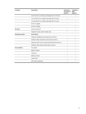
... Li-ion battery with target life of 4 hours 12-cell 8.80-Ah Li-ion battery with target life of 5 hours 90-W AC adapter 65-W AC adapter Security cable slot Fingerprint reader (select models only) Preinstalled: Windows Vista® Business (32-bit) Service Pack 2 Windows Vista Home ...Basic (32-bit) Service Pack 2 Windows Vista Premium (32-bit and-64 bit) Service Pack 2 Windows Vista Ultimate (64-bit) Service Pack 2 AC adapter Battery (system) Hard drive Memory module Optical drive Mini Card components Computers Computers with discrete UMA graphics graphics √ √ √ √ ...
... Li-ion battery with target life of 4 hours 12-cell 8.80-Ah Li-ion battery with target life of 5 hours 90-W AC adapter 65-W AC adapter Security cable slot Fingerprint reader (select models only) Preinstalled: Windows Vista® Business (32-bit) Service Pack 2 Windows Vista Home ...Basic (32-bit) Service Pack 2 Windows Vista Premium (32-bit and-64 bit) Service Pack 2 Windows Vista Ultimate (64-bit) Service Pack 2 AC adapter Battery (system) Hard drive Memory module Optical drive Mini Card components Computers Computers with discrete UMA graphics graphics √ √ √ √ ...
Service Guide
Page 21
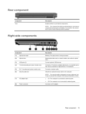
...Connects a TV antenna, a digital cable device, or a satellite device that receives standard or high-definition TV broadcasts. Connects an AC adapter. Rear component 13 Connect optional USB devices. Connects a modem cable. It is being mishandled or stolen. ● On: The ...ports (2) (4) TV antenna/cable jack (select models only) (5) RJ-11 (modem) jack (select models only) (6) Security cable slot (7) AC adapter light (8) Power connector Description Blinking: The optical drive is normal for the internal fan to cool internal components and prevent overheating. NOTE: The ...
...Connects a TV antenna, a digital cable device, or a satellite device that receives standard or high-definition TV broadcasts. Connects an AC adapter. Rear component 13 Connect optional USB devices. Connects a modem cable. It is being mishandled or stolen. ● On: The ...ports (2) (4) TV antenna/cable jack (select models only) (5) RJ-11 (modem) jack (select models only) (6) Security cable slot (7) AC adapter light (8) Power connector Description Blinking: The optical drive is normal for the internal fan to cool internal components and prevent overheating. NOTE: The ...
Service Guide
Page 38
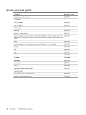
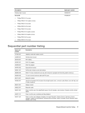
Miscellaneous parts Description Spare part number Notebook sleeve, 16-inch, white AC adapters 533534-001 65-W AC adapter 463958-001 90-W AC adapter 463955-001 Power cords: Argentina 490371-D01 Australia and New Zealand 490371-011 Belgium, Bulgaria, the Czech Republic, Finland, France, Germany, Greece, Hungary, Iceland, the ...
Miscellaneous parts Description Spare part number Notebook sleeve, 16-inch, white AC adapters 533534-001 65-W AC adapter 463958-001 90-W AC adapter 463955-001 Power cords: Argentina 490371-D01 Australia and New Zealand 490371-011 Belgium, Bulgaria, the Czech Republic, Finland, France, Germany, Greece, Hungary, Iceland, the ...
Service Guide
Page 39
...-001 483862-001 488317-001 489822-001 490371-001 490371-011 490371-021 Description Headset, wired with volume control Wireless laser mouse RTC battery 90-W AC adapter 65-W AC adapter ExpressCard module Full-function remote control with teletext DVB-T TV tuner module (for use only with computers equipped with discrete graphics memory) TV tuner...
...-001 483862-001 488317-001 489822-001 490371-001 490371-011 490371-021 Description Headset, wired with volume control Wireless laser mouse RTC battery 90-W AC adapter 65-W AC adapter ExpressCard module Full-function remote control with teletext DVB-T TV tuner module (for use only with computers equipped with discrete graphics memory) TV tuner...

Service Guide
Page 56
... battery into place. 48 Chapter 4 Removal and replacement procedures Disconnect the power from the computer by first unplugging the power cord from the AC outlet and then unplugging the AC adapter from the computer (3). To insert the battery, insert the rear edge of the battery downward until it from the computer. Battery Description...
... battery into place. 48 Chapter 4 Removal and replacement procedures Disconnect the power from the computer by first unplugging the power cord from the AC outlet and then unplugging the AC adapter from the computer (3). To insert the battery, insert the rear edge of the battery downward until it from the computer. Battery Description...
Service Guide
Page 57
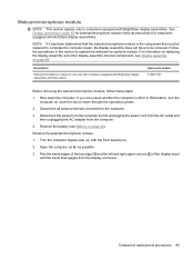
.../microphone module for computers equipped with BrightView display assemblies. Disconnect the power from the computer by first unplugging the power cord from the AC outlet and then unplugging the AC adapter from the display enclosure. Open the computer as far as possible. 3. Component replacement procedures 49 Shut down through the operating system. 2. If...
.../microphone module for computers equipped with BrightView display assemblies. Disconnect the power from the computer by first unplugging the power cord from the AC outlet and then unplugging the AC adapter from the display enclosure. Open the computer as far as possible. 3. Component replacement procedures 49 Shut down through the operating system. 2. If...

Service Guide
Page 59
...;6.5 screw (1) that secures the optical drive to the computer. 3. Disconnect the power from the computer by first unplugging the power cord from the AC outlet and then unplugging the AC adapter from the optical drive.) 4. Remove the optical drive: 1. Position the computer with the optical drive bracket toward you. 2. Remove the optical drive...
...;6.5 screw (1) that secures the optical drive to the computer. 3. Disconnect the power from the computer by first unplugging the power cord from the AC outlet and then unplugging the AC adapter from the optical drive.) 4. Remove the optical drive: 1. Position the computer with the optical drive bracket toward you. 2. Remove the optical drive...

Service Guide
Page 61
... remove the cover (3). Shut down through the operating system. 2. Disconnect the power from the computer by first unplugging the power cord from the AC outlet and then unplugging the AC adapter from the computer.) Component replacement procedures 53 Remove the memory module: 1. Lift the rear edge (2) of the cover, swing it down the...
... remove the cover (3). Shut down through the operating system. 2. Disconnect the power from the computer by first unplugging the power cord from the AC outlet and then unplugging the AC adapter from the computer.) Component replacement procedures 53 Remove the memory module: 1. Lift the rear edge (2) of the cover, swing it down the...

Service Guide
Page 63
... these steps: 1. Shut down through the operating system. 2. Disconnect the power from the computer by first unplugging the power cord from the AC outlet and then unplugging the AC Adapter from the slot at an angle. Remove the TV tuner module: 1. Component replacement procedures 55 Disconnect the TV tuner module antenna cable (1) from...
... these steps: 1. Shut down through the operating system. 2. Disconnect the power from the computer by first unplugging the power cord from the AC outlet and then unplugging the AC Adapter from the slot at an angle. Remove the TV tuner module: 1. Component replacement procedures 55 Disconnect the TV tuner module antenna cable (1) from...

Service Guide
Page 64
Disconnect the power from the computer by first unplugging the power cord from the AC outlet and then unplugging the AC adapter from the socket on page 53). Shut down through the operating system. 2. Disconnect all external devices connected to pry the RTC battery from the computer. 4. ...
Disconnect the power from the computer by first unplugging the power cord from the AC outlet and then unplugging the AC adapter from the socket on page 53). Shut down through the operating system. 2. Disconnect all external devices connected to pry the RTC battery from the computer. 4. ...

Service Guide
Page 65
..., and 4 rubber isolators) Before removing the hard drive, follow these steps: 1. Disconnect the power from the computer by first unplugging the power cord from the AC outlet and then unplugging the AC adapter from the computer. 4.
..., and 4 rubber isolators) Before removing the hard drive, follow these steps: 1. Disconnect the power from the computer by first unplugging the power cord from the AC outlet and then unplugging the AC adapter from the computer. 4.
Service Guide
Page 70
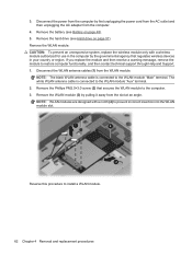
... WLAN module to prevent incorrect insertion into the WLAN module slot. Remove the WLAN module (3) by first unplugging the power cord from the AC outlet and then unplugging the AC adapter from the WLAN module. Remove the hard drive (see Battery on page 57). Remove the WLAN module: CAUTION: To prevent an unresponsive...
... WLAN module to prevent incorrect insertion into the WLAN module slot. Remove the WLAN module (3) by first unplugging the power cord from the AC outlet and then unplugging the AC adapter from the WLAN module. Remove the hard drive (see Battery on page 57). Remove the WLAN module: CAUTION: To prevent an unresponsive...

Service Guide
Page 71
... removing the switch cover and keyboard, follow these steps: 1. Disconnect the power from the computer by first unplugging the power cord from the AC outlet and then unplugging the AC adapter from the computer. 4. Remove the switch cover and keyboard: 1. Shut down through the operating system. 2. Component replacement procedures 63 If you . Disconnect...
... removing the switch cover and keyboard, follow these steps: 1. Disconnect the power from the computer by first unplugging the power cord from the AC outlet and then unplugging the AC adapter from the computer. 4. Remove the switch cover and keyboard: 1. Shut down through the operating system. 2. Component replacement procedures 63 If you . Disconnect...

Service Guide
Page 75
... power button board to install the power button board. Disconnect the power from the computer by first unplugging the power cord from the AC outlet and then unplugging the AC Adapter from the computer. 4. Remove the power button board: 1. Reverse this procedure to the switch cover. 3. Component replacement procedures 67 Remove the battery...
... power button board to install the power button board. Disconnect the power from the computer by first unplugging the power cord from the AC outlet and then unplugging the AC Adapter from the computer. 4. Remove the power button board: 1. Reverse this procedure to the switch cover. 3. Component replacement procedures 67 Remove the battery...

Service Guide
Page 76
... a webcam, 2 microphones, and 2 wireless antenna transceivers and cables. Disconnect the power from the computer by first unplugging the power cord from the AC outlet and then unplugging the AC adapter from the computer. 4. If you are unsure whether the computer is off or in MTV2 artist edition computers Spare part number 512358-001...
... a webcam, 2 microphones, and 2 wireless antenna transceivers and cables. Disconnect the power from the computer by first unplugging the power cord from the AC outlet and then unplugging the AC adapter from the computer. 4. If you are unsure whether the computer is off or in MTV2 artist edition computers Spare part number 512358-001...

Service Guide
Page 86
If you . 2. Disconnect the power from the computer by first unplugging the power cord from the AC outlet and then unplugging the AC adapter from the system board (1). 3. Switch cover and keyboard (see Switch cover and keyboard on , and then shut it down the computer. Lift the speaker up , ...
If you . 2. Disconnect the power from the computer by first unplugging the power cord from the AC outlet and then unplugging the AC adapter from the system board (1). 3. Switch cover and keyboard (see Switch cover and keyboard on , and then shut it down the computer. Lift the speaker up , ...
Service Guide
Page 87
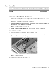
... from the computer. 4. Shut down through the operating system. 2. Disconnect the power from the computer by first unplugging the power cord from the AC outlet and then unplugging the AC Adapter from the top cover (3). 4. Remove the Phillips PM2.0×3.0 screw (2) that secures the Bluetooth module to the computer. 3. Remove the Bluetooth module...
... from the computer. 4. Shut down through the operating system. 2. Disconnect the power from the computer by first unplugging the power cord from the AC outlet and then unplugging the AC Adapter from the top cover (3). 4. Remove the Phillips PM2.0×3.0 screw (2) that secures the Bluetooth module to the computer. 3. Remove the Bluetooth module...

Service Guide
Page 88
Switch cover and keyboard (see Optical drive on page 51) c. Disconnect the power from the computer by first unplugging the power cord from the AC outlet and then unplugging the AC adapter from the computer. 4. Optical drive (see Switch cover and keyboard on page 63) d. Remove the 10 Phillips PM2.5×7.0 screws (1) that secure...
Switch cover and keyboard (see Optical drive on page 51) c. Disconnect the power from the computer by first unplugging the power cord from the AC outlet and then unplugging the AC adapter from the computer. 4. Optical drive (see Switch cover and keyboard on page 63) d. Remove the 10 Phillips PM2.5×7.0 screws (1) that secure...


