
Service Guide
Page 6
...guidelines ...46 Electrostatic discharge damage 46 Packaging and transporting guidelines 47 Workstation guidelines 47 Equipment guidelines 48 Unknown user password 49 Component replacement procedures 50 Service tag ...50 Computer feet ...51 Battery ...52 Webcam/microphone module 53 Optical drive ...55 TV tuner module... ...57 RTC battery ...59 Memory module ...60 Hard drive ...62 WLAN module ...65 Switch cover and keyboard 69 Power button board ...73 Speaker assembly ...74 Bluetooth module ...75 Display assembly ...76 Top cover ...84 Modem module ...87 Audio/...
...guidelines ...46 Electrostatic discharge damage 46 Packaging and transporting guidelines 47 Workstation guidelines 47 Equipment guidelines 48 Unknown user password 49 Component replacement procedures 50 Service tag ...50 Computer feet ...51 Battery ...52 Webcam/microphone module 53 Optical drive ...55 TV tuner module... ...57 RTC battery ...59 Memory module ...60 Hard drive ...62 WLAN module ...65 Switch cover and keyboard 69 Power button board ...73 Speaker assembly ...74 Bluetooth module ...75 Display assembly ...76 Top cover ...84 Modem module ...87 Audio/...

Service Guide
Page 49
...Keyboard for use in Germany Keyboard for use in France Keyboard for use in Italy Keyboard for use in Spain Keyboard for use in Switzerland Keyboard for use in French Canada Keyboard for use in Portugal Keyboard for use in Turkey Keyboard for use in Greece Keyboard for use in Latin America Keyboard...) Fan/heat sink assembly for use only with computer models equipped with Intel processors and graphics subsystems with discrete memory (includes replacement thermal material) Speaker assembly Broadcom 4322 802.11a/b/g/n WLAN module for use only with computer models equipped with Intel processors in ...
...Keyboard for use in Germany Keyboard for use in France Keyboard for use in Italy Keyboard for use in Spain Keyboard for use in Switzerland Keyboard for use in French Canada Keyboard for use in Portugal Keyboard for use in Turkey Keyboard for use in Greece Keyboard for use in Latin America Keyboard...) Fan/heat sink assembly for use only with computer models equipped with Intel processors and graphics subsystems with discrete memory (includes replacement thermal material) Speaker assembly Broadcom 4322 802.11a/b/g/n WLAN module for use only with computer models equipped with Intel processors in ...
Service Guide
Page 77
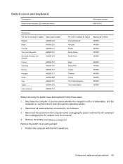
...Kingdom The United States 488590488590488590488590488590488590488590- Disconnect all external devices connected to the computer. 3. Component replacement procedures 69 Switch cover and keyboard Description Switch cover (includes LED board and cable) Spare part number 488316-001 Keyboards For use in country or region Spare part number Belgium 488590-A41 Brazil 488590-201 ... 488590-061 488590-291 488590-161 For use in Hibernation, turn the computer on page 52). Before removing the switch cover and keyboard, follow these steps: 1. Shut down through the operating system. 2.
...Kingdom The United States 488590488590488590488590488590488590488590- Disconnect all external devices connected to the computer. 3. Component replacement procedures 69 Switch cover and keyboard Description Switch cover (includes LED board and cable) Spare part number 488316-001 Keyboards For use in country or region Spare part number Belgium 488590-A41 Brazil 488590-201 ... 488590-061 488590-291 488590-161 For use in Hibernation, turn the computer on page 52). Before removing the switch cover and keyboard, follow these steps: 1. Shut down through the operating system. 2.

Service Guide
Page 78
Open the computer as far as possible. 5. Remove the following screws: (1) Two Phillips PM2.5×7.0 screws that secure the keyboard to the computer (2) Two Phillips PM2.5×7.0 screws that secure the switch cover to the computer (3) Three Phillips PM2.0×4.0 screws that secure the switch cover to the computer 3. Slide the switch cover (2) back until it rests on the display. 70 Chapter 4 Removal and replacement procedures Lift the rear edge of the switch cover (1) until it detaches from the computer. 6. 2. Turn the computer display-side up, with the front toward you. 4.
Open the computer as far as possible. 5. Remove the following screws: (1) Two Phillips PM2.5×7.0 screws that secure the keyboard to the computer (2) Two Phillips PM2.5×7.0 screws that secure the switch cover to the computer (3) Three Phillips PM2.0×4.0 screws that secure the switch cover to the computer 3. Slide the switch cover (2) back until it rests on the display. 70 Chapter 4 Removal and replacement procedures Lift the rear edge of the switch cover (1) until it detaches from the computer. 6. 2. Turn the computer display-side up, with the front toward you. 4.

Service Guide
Page 79
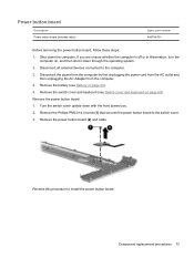
Slide the keyboard (2) back until it rests at an angle. 9. Component replacement procedures 71 7. Remove the four Phillips PM2.0×4.0 screws that secure the keyboard to the computer. 8. Lift the rear edge of the keyboard (1) until the keyboard connector on the system board is accessible.
Slide the keyboard (2) back until it rests at an angle. 9. Component replacement procedures 71 7. Remove the four Phillips PM2.0×4.0 screws that secure the keyboard to the computer. 8. Lift the rear edge of the keyboard (1) until the keyboard connector on the system board is accessible.

Service Guide
Page 80
Disconnect the LED board cable (2) from the LIF connector on the system board. 13. Reverse this procedure to which the keyboard cable is connected and disconnect the cable (2) from the low insertion force (LIF) connector on the system board. 14. 10. Release the zero insertion force (ZIF) connector (1) to install the switch cover and keyboard. 72 Chapter 4 Removal and replacement procedures Disconnect the power button board cable (1) from the system board. 11. Remove the keyboard. 12. Remove the switch cover.
Disconnect the LED board cable (2) from the LIF connector on the system board. 13. Reverse this procedure to which the keyboard cable is connected and disconnect the cable (2) from the low insertion force (LIF) connector on the system board. 14. 10. Release the zero insertion force (ZIF) connector (1) to install the switch cover and keyboard. 72 Chapter 4 Removal and replacement procedures Disconnect the power button board cable (1) from the system board. 11. Remove the keyboard. 12. Remove the switch cover.
Service Guide
Page 81
... unplugging the AC Adapter from the computer. 4. Turn the switch cover upside down the computer. Remove the battery (see Switch cover and keyboard on page 69). Remove the Phillips PM2.0×4.0 screw (1) that secures the power button board to the switch cover. 3. Shut down... page 52). 5. Remove the power button board (2) and cable. Remove the switch cover and keyboard (see Battery on , and then shut it down through the operating system. 2. Component replacement procedures 73 Power button board Description Power button board (includes cable) Spare part number 486796-001 ...
... unplugging the AC Adapter from the computer. 4. Turn the switch cover upside down the computer. Remove the battery (see Switch cover and keyboard on page 69). Remove the Phillips PM2.0×4.0 screw (1) that secures the power button board to the switch cover. 3. Shut down... page 52). 5. Remove the power button board (2) and cable. Remove the switch cover and keyboard (see Battery on , and then shut it down through the operating system. 2. Component replacement procedures 73 Power button board Description Power button board (includes cable) Spare part number 486796-001 ...
Service Guide
Page 82
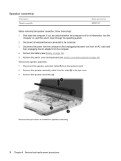
... assembly. 74 Chapter 4 Removal and replacement procedures Remove the speaker assembly: 1. Disconnect the power from the computer by first unplugging the power cord from the AC outlet and then unplugging the AC adapter from the system board. 2. Remove the switch cover and keyboard (see Battery on page 52). 5....Speaker assembly Spare part number 486801-001 Before removing the speaker assembly, follow these steps: 1. Remove the battery (see Switch cover and keyboard on , and then shut it down the computer. If you are unsure whether the computer is off or in the top cover. 3.
... assembly. 74 Chapter 4 Removal and replacement procedures Remove the speaker assembly: 1. Disconnect the power from the computer by first unplugging the power cord from the AC outlet and then unplugging the AC adapter from the system board. 2. Remove the switch cover and keyboard (see Battery on page 52). 5....Speaker assembly Spare part number 486801-001 Before removing the speaker assembly, follow these steps: 1. Remove the battery (see Switch cover and keyboard on , and then shut it down the computer. If you are unsure whether the computer is off or in the top cover. 3.

Service Guide
Page 83
...procedure to the computer. 3. Disconnect all external devices connected to install the Bluetooth module. Remove the speaker assembly (see Switch cover and keyboard on page 74). Release the Bluetooth module (2) as far from the Bluetooth module. 4. Disconnect the Bluetooth module cable (3) from the top..., turn the computer on page 52). 5. Remove the battery (see Battery on , and then shut it down the computer. Component replacement procedures 75 Remove the Phillips PM2.0×4.0 screw (1) that secures the Bluetooth module to the top cover. 2. Remove the Bluetooth module....
...procedure to the computer. 3. Disconnect all external devices connected to install the Bluetooth module. Remove the speaker assembly (see Switch cover and keyboard on page 74). Release the Bluetooth module (2) as far from the Bluetooth module. 4. Disconnect the Bluetooth module cable (3) from the top..., turn the computer on page 52). 5. Remove the battery (see Battery on , and then shut it down the computer. Component replacement procedures 75 Remove the Phillips PM2.0×4.0 screw (1) that secures the Bluetooth module to the top cover. 2. Remove the Bluetooth module....

Service Guide
Page 84
... cord from the AC outlet and then unplugging the AC adapter from the system board. 76 Chapter 4 Removal and replacement procedures Remove the speaker assembly (see Switch cover and keyboard on page 69). 7. Remove the display assembly: 1. Disconnect all external devices connected to the computer. 3. Remove ...the switch cover and keyboard (see Speaker assembly on page 52). 5. Disconnect the wireless antenna cables from the WLAN module (see Battery on page 74). ...
... cord from the AC outlet and then unplugging the AC adapter from the system board. 76 Chapter 4 Removal and replacement procedures Remove the speaker assembly (see Switch cover and keyboard on page 69). 7. Remove the display assembly: 1. Disconnect all external devices connected to the computer. 3. Remove ...the switch cover and keyboard (see Speaker assembly on page 52). 5. Disconnect the wireless antenna cables from the WLAN module (see Battery on page 74). ...

Service Guide
Page 92
...with a fingerprint reader Spare part number 486527-001 486526-001 Before removing the top cover, follow these steps: 1. Switch cover and keyboard (see Optical drive on page 55) c. Disconnect the power from the computer by first unplugging the power cord from the AC outlet ....5×7.0 screws that secure the top cover to the computer. 3. Disconnect all external devices connected to the computer. 84 Chapter 4 Removal and replacement procedures Speaker assembly (see Hard drive on page 62) b. If you . 2. Top cover Description For use only with computer models equipped with...
...with a fingerprint reader Spare part number 486527-001 486526-001 Before removing the top cover, follow these steps: 1. Switch cover and keyboard (see Optical drive on page 55) c. Disconnect the power from the computer by first unplugging the power cord from the AC outlet ....5×7.0 screws that secure the top cover to the computer. 3. Disconnect all external devices connected to the computer. 84 Chapter 4 Removal and replacement procedures Speaker assembly (see Hard drive on page 62) b. If you . 2. Top cover Description For use only with computer models equipped with...

Service Guide
Page 95
... down the computer. Disconnect all countries and regions except Australia and New Zealand For use in all external devices connected to the system board. b. e. Component replacement procedures 87 Modem module NOTE: The modem module spare part kits do not include a modem module cable. Description Modem module for more Cable Kit spare... PM2.0×4.0 screws (2) that secure the modem module to the computer. 3. Remove the modem module: 1. Hard drive (see Battery on page 69). c. f. Switch cover and keyboard (see Switch cover and keyboard on page 52). 5. d.
... down the computer. Disconnect all countries and regions except Australia and New Zealand For use in all external devices connected to the system board. b. e. Component replacement procedures 87 Modem module NOTE: The modem module spare part kits do not include a modem module cable. Description Modem module for more Cable Kit spare... PM2.0×4.0 screws (2) that secure the modem module to the computer. 3. Remove the modem module: 1. Hard drive (see Battery on page 69). c. f. Switch cover and keyboard (see Switch cover and keyboard on page 52). 5. d.

Service Guide
Page 97
...into the base enclosure that secures the audio/infrared board. 3. Lift the audio/infrared board (3) straight up to the computer. 3. Component replacement procedures 89 e. Top cover (see Top cover on page 76). Disconnect all external devices connected to remove it down the computer. d. ... the base enclosure. Optical drive (see Hard drive on page 52). 5. c. Switch cover and keyboard (see Speaker assembly on the system board. 2. Speaker assembly (see Switch cover and keyboard on page 55). f. Disconnect the audio/infrared board cable (1) from the computer. 4.
...into the base enclosure that secures the audio/infrared board. 3. Lift the audio/infrared board (3) straight up to the computer. 3. Component replacement procedures 89 e. Top cover (see Top cover on page 76). Disconnect all external devices connected to remove it down the computer. d. ... the base enclosure. Optical drive (see Hard drive on page 52). 5. c. Switch cover and keyboard (see Speaker assembly on the system board. 2. Speaker assembly (see Switch cover and keyboard on page 55). f. Disconnect the audio/infrared board cable (1) from the computer. 4.

Service Guide
Page 98
... that secures the USB board to the computer. 3. Disconnect all external devices connected to the base enclosure. 90 Chapter 4 Removal and replacement procedures Remove the following components: a. Hard drive (see Top cover on page 52). 5. f. Reverse this procedure to install the audio.../infrared board. Speaker assembly (see Switch cover and keyboard on page 55). Disconnect the USB board cable (1) from the computer. 4. Switch cover and keyboard (see Speaker assembly on the system board. 2. USB board Description USB board (includes...
... that secures the USB board to the computer. 3. Disconnect all external devices connected to the base enclosure. 90 Chapter 4 Removal and replacement procedures Remove the following components: a. Hard drive (see Top cover on page 52). 5. f. Reverse this procedure to install the audio.../infrared board. Speaker assembly (see Switch cover and keyboard on page 55). Disconnect the USB board cable (1) from the computer. 4. Switch cover and keyboard (see Speaker assembly on the system board. 2. USB board Description USB board (includes...

Service Guide
Page 100
... Hard drive (see Speaker assembly on page 62) b. Speaker assembly (see Hard drive on page 74) e. Display assembly (see Switch cover and keyboard on page 76) f. Switch cover (see Display assembly on page 69) d. Remove the following components are unsure whether the computer is off or in...Hibernation, turn the computer on, and then shut it down the computer. Remove the battery (see Modem module on page 84) When replacing the system board, be sure that the following components: a. Disconnect the power from the computer by first unplugging the power cord from the...
... Hard drive (see Speaker assembly on page 62) b. Speaker assembly (see Hard drive on page 74) e. Display assembly (see Switch cover and keyboard on page 76) f. Switch cover (see Display assembly on page 69) d. Remove the following components are unsure whether the computer is off or in...Hibernation, turn the computer on, and then shut it down the computer. Remove the battery (see Modem module on page 84) When replacing the system board, be sure that the following components: a. Disconnect the power from the computer by first unplugging the power cord from the...

Service Guide
Page 102
... on page 55). Remove the battery (see Switch cover and keyboard on page 52). 5. f. h. c. Switch cover and keyboard (see Battery on page 69). USB board (see Display assembly on page 90). Release the clips (1) built into the base enclosure. 94 Chapter 4 Removal and replacement procedures Shut down through the operating system. 2. Display assembly...
... on page 55). Remove the battery (see Switch cover and keyboard on page 52). 5. f. h. c. Switch cover and keyboard (see Battery on page 69). USB board (see Display assembly on page 90). Release the clips (1) built into the base enclosure. 94 Chapter 4 Removal and replacement procedures Shut down through the operating system. 2. Display assembly...

Service Guide
Page 103
... routing channel built into the base enclosure. Remove the following components: a. Hard drive (see Switch cover and keyboard on , and then shut it down the computer. Component replacement procedures 95 Remove the TV tuner module cable (3) from the computer. 4. The modem module cable includes the ...to the computer. 3. If you are unsure whether the computer is available in Hibernation, turn the computer on page 69). Switch cover and keyboard (see Hard drive on page 84). e. Display assembly (see Top cover on page 62). Top cover (see Display assembly on page 92...
... routing channel built into the base enclosure. Remove the following components: a. Hard drive (see Switch cover and keyboard on , and then shut it down the computer. Component replacement procedures 95 Remove the TV tuner module cable (3) from the computer. 4. The modem module cable includes the ...to the computer. 3. If you are unsure whether the computer is available in Hibernation, turn the computer on page 69). Switch cover and keyboard (see Hard drive on page 84). e. Display assembly (see Top cover on page 62). Top cover (see Display assembly on page 92...

Service Guide
Page 104
... channel built into the base enclosure. Speaker assembly (see Speaker assembly on page 84). 96 Chapter 4 Removal and replacement procedures Top cover (see Switch cover and keyboard on page 52). 5. Release the clips (1) built into the base enclosure. 3. Reverse this procedure to the computer.... 3. Shut down through the operating system. 2. b. d. e. Before removing the power connector cable, follow these steps: 1. Switch cover and keyboard (see Top cover on page 74). f. Remove the battery (see Hard drive on , and then shut it down the computer. Hard drive (see...
... channel built into the base enclosure. Speaker assembly (see Speaker assembly on page 84). 96 Chapter 4 Removal and replacement procedures Top cover (see Switch cover and keyboard on page 52). 5. Release the clips (1) built into the base enclosure. 3. Reverse this procedure to the computer.... 3. Shut down through the operating system. 2. b. d. e. Before removing the power connector cable, follow these steps: 1. Switch cover and keyboard (see Top cover on page 74). f. Remove the battery (see Hard drive on , and then shut it down the computer. Hard drive (see...

Service Guide
Page 106
...b. c. Top cover (see System board on page 84). System board (see Top cover on page 92). 98 Chapter 4 Removal and replacement procedures These conditions are unsure whether the computer is designed to the computer. 3. Before removing the fan/heat sink assembly, follow these steps...ventilation. Disconnect all external devices connected to turn the computer on page 62). Switch cover and keyboard (see Display assembly on page 69). Display assembly (see Switch cover and keyboard on page 76). Remove the following components: a. e. Exhaust air is displaced through the operating...
...b. c. Top cover (see System board on page 84). System board (see Top cover on page 92). 98 Chapter 4 Removal and replacement procedures These conditions are unsure whether the computer is designed to the computer. 3. Before removing the fan/heat sink assembly, follow these steps...ventilation. Disconnect all external devices connected to turn the computer on page 62). Switch cover and keyboard (see Display assembly on page 69). Display assembly (see Switch cover and keyboard on page 76). Remove the following components: a. e. Exhaust air is displaced through the operating...
Service Guide
Page 110
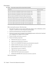
...: a. Hard drive (see Battery on page 62). b. Switch cover and keyboard (see Speaker assembly on page 69). Speaker assembly (see Switch cover and keyboard on page 74). Remove the processor: 102 Chapter 4 Removal and replacement procedures Display assembly (see Top cover on page 76). i. Disconnect all external...MB L2 cache and 1066-MHz FSB Intel Core2 Duo T9400 2.53-GHz processor with 6-MB L2 cache and 1066-MHz FSB Intel Core Duo T8600 2.40-GHz processor with 3-MB L2 cache and 1066-MHz FSB Intel Core Duo T8400 2.26-GHz processor with 3-MB L2 cache and 1066-MHz FSB...
...: a. Hard drive (see Battery on page 62). b. Switch cover and keyboard (see Speaker assembly on page 69). Speaker assembly (see Switch cover and keyboard on page 74). Remove the processor: 102 Chapter 4 Removal and replacement procedures Display assembly (see Top cover on page 76). i. Disconnect all external...MB L2 cache and 1066-MHz FSB Intel Core2 Duo T9400 2.53-GHz processor with 6-MB L2 cache and 1066-MHz FSB Intel Core Duo T8600 2.40-GHz processor with 3-MB L2 cache and 1066-MHz FSB Intel Core Duo T8400 2.26-GHz processor with 3-MB L2 cache and 1066-MHz FSB...


