Service Manual
Page 10
Table of Contents Right Hand Trim 8-20 Left Hand Trim 8-22 Back Cover 8-23 Ink Tubes System 8-25 EMC Covers 8-32 Encoder Strip 8-34 Trailing Cable 8-36 Tensioner Assembly 8-42 Carriage Assembly and Belt 8-46 Scan-Axis Motor 8-53 Cutter Assembly 8-56 Ink Supply Station (ISS) 8-60 Air Pressurization System (APS) 8-... 8-101 Media Sensor 8-102 Entry Roller 8-104 Center Guide Assembly 8-105 Drive Roller Gear 8-107 Front Platen Assembly 8-108 Center Platen Assembly 8-110 Deflectors 8-112 8 HP DesignJet 5000 Series Printers Service Manual
Table of Contents Right Hand Trim 8-20 Left Hand Trim 8-22 Back Cover 8-23 Ink Tubes System 8-25 EMC Covers 8-32 Encoder Strip 8-34 Trailing Cable 8-36 Tensioner Assembly 8-42 Carriage Assembly and Belt 8-46 Scan-Axis Motor 8-53 Cutter Assembly 8-56 Ink Supply Station (ISS) 8-60 Air Pressurization System (APS) 8-... 8-101 Media Sensor 8-102 Entry Roller 8-104 Center Guide Assembly 8-105 Drive Roller Gear 8-107 Front Platen Assembly 8-108 Center Platen Assembly 8-110 Deflectors 8-112 8 HP DesignJet 5000 Series Printers Service Manual
Service Manual
Page 29
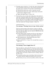
... media sensor cable is not damaged and that the Trailing cable is incorrectly connected, and it is not connected correctly (especially after the insertion of the Ink cartridge Tube Connector. To verify this message appears after the Tubes have been a bad HP DesignJet 5000 Series Printers ... during initialization, the media sensor is clipped correctly. If the message comes up correctly. n To isolate the problem, remove the Trailing Cable from the back of the media. If the message comes up correctly, the problem could have been replaced). n Replace the Media...
... media sensor cable is not damaged and that the Trailing cable is incorrectly connected, and it is not connected correctly (especially after the insertion of the Ink cartridge Tube Connector. To verify this message appears after the Tubes have been a bad HP DesignJet 5000 Series Printers ... during initialization, the media sensor is clipped correctly. If the message comes up correctly. n To isolate the problem, remove the Trailing Cable from the back of the media. If the message comes up correctly, the problem could have been replaced). n Replace the Media...

Service Manual
Page 30
.... n If the Printer did not initialize correctly, even after removing the Trailing Cable, the problem is defective. In this case, first try replacing the Trailing Cable and then the Carriage Assembly. If, after removing the Trailing Cable and the ISS cable, replace the Main PCA. 1-18 HP DesignJet 5000 Series Printers Service Manual n If the Printer still does not initialize...
.... n If the Printer did not initialize correctly, even after removing the Trailing Cable, the problem is defective. In this case, first try replacing the Trailing Cable and then the Carriage Assembly. If, after removing the Trailing Cable and the ISS cable, replace the Main PCA. 1-18 HP DesignJet 5000 Series Printers Service Manual n If the Printer still does not initialize...
Service Manual
Page 59
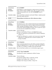
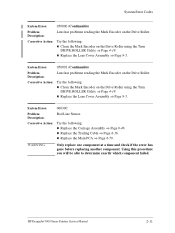
... the Window is opened during the cutting operation. Corrective Action: Try the following : n Check the Trailing Cable is nothing wrong with the Carriage. HP DesignJet 5000 Series Printers Service Manual 2-7 NOTE This problem is a problem of the Printhead cleaners by an incorrectly ... suddenly stops. System Error: 01002D (Non-Continuable) Problem Description: The Main PCA cannot communicate with the Printer. n Replace the Trailing Cable ⇒ Page 8-36. n Replace the Carriage Assembly ⇒ Page 8-46. System Error: ffff ffff 036000bd Problem Description: This...
... the Window is opened during the cutting operation. Corrective Action: Try the following : n Check the Trailing Cable is nothing wrong with the Carriage. HP DesignJet 5000 Series Printers Service Manual 2-7 NOTE This problem is a problem of the Printhead cleaners by an incorrectly ... suddenly stops. System Error: 01002D (Non-Continuable) Problem Description: The Main PCA cannot communicate with the Printer. n Replace the Trailing Cable ⇒ Page 8-36. n Replace the Carriage Assembly ⇒ Page 8-46. System Error: ffff ffff 036000bd Problem Description: This...
Service Manual
Page 63
... 4-18 n Replace the Lens Cover Assembly ⇒ Page 9-5. n Replace the Main PCA ⇒ Page 8-79. HP DesignJet 5000 Series Printers Service Manual 2-11 Corrective Action: Try the following : n Replace the Carriage Assembly ⇒ Page 8-46 n Replace the Trailing Cable ⇒ Page 8-36. System Error Codes System Error: 050000 (Continuable) Problem Description: Lens has problems reading...
... 4-18 n Replace the Lens Cover Assembly ⇒ Page 9-5. n Replace the Main PCA ⇒ Page 8-79. HP DesignJet 5000 Series Printers Service Manual 2-11 Corrective Action: Try the following : n Replace the Carriage Assembly ⇒ Page 8-46 n Replace the Trailing Cable ⇒ Page 8-36. System Error Codes System Error: 050000 (Continuable) Problem Description: Lens has problems reading...
Service Manual
Page 68
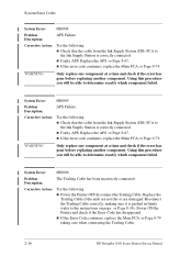
...If the Error Code continues, replace the Main PCA ⇒ Page 8-79 taking care when connecting the Trailing Cable. 2-16 HP DesignJet 5000 Series Printers Service Manual Using this procedure you will be able to the Ink Supply Station is correctly connected.... System Error: 0B0006 Problem Description: The Trailing Cable has been incorrectly connected. System Error Codes System Error: 0B0004 Problem Description: ...
...If the Error Code continues, replace the Main PCA ⇒ Page 8-79 taking care when connecting the Trailing Cable. 2-16 HP DesignJet 5000 Series Printers Service Manual Using this procedure you will be able to the Ink Supply Station is correctly connected.... System Error: 0B0006 Problem Description: The Trailing Cable has been incorrectly connected. System Error Codes System Error: 0B0004 Problem Description: ...

Service Manual
Page 89
...the Carriage Assembly and the Main PCA and if the cable is removed from the Printhead. Do the following : n All Printheads installed are NOT wrong type i.e. HP DesignJet 5000 Series Printers Service Manual 3-13 n Ensure that the ...HP Ink Supplies Troubleshooting Printhead Errors (First Digit = 0, 1, 2, 3, 4, 5) If you think your Printheads too frequently you can damage the Printhead and reduce print quality (See Page 9-6 for Maintenance Procedures). This can check Printhead nozzle status by printing the Diagnostic Print ⇒ Refer to the Carriage. 2 Check that the Trailing Cable...
...the Carriage Assembly and the Main PCA and if the cable is removed from the Printhead. Do the following : n All Printheads installed are NOT wrong type i.e. HP DesignJet 5000 Series Printers Service Manual 3-13 n Ensure that the ...HP Ink Supplies Troubleshooting Printhead Errors (First Digit = 0, 1, 2, 3, 4, 5) If you think your Printheads too frequently you can damage the Printhead and reduce print quality (See Page 9-6 for Maintenance Procedures). This can check Printhead nozzle status by printing the Diagnostic Print ⇒ Refer to the Carriage. 2 Check that the Trailing Cable...
Service Manual
Page 90
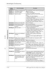
... normal Printheads. XX12 Replace Printhead does not match the rest of Printhead installed. Check Trailing Cable connections between the Carriage Assembly and the Main PCA and replace the Trailing Cable if damaged ⇒ Page 8-36. 6. XX14 Replace The Printhead has an internal ... short XX18 Replace The Printhead smartchip detects an unapproved manufacturer. 1. If the message persists replace the Printhead(s). 3-14 HP DesignJet 5000 Series Printers Service Manual If priming Tubes install new Setup Printheads otherwise install normal Printheads. Replace the Carriage Assembly ⇒...
... normal Printheads. XX12 Replace Printhead does not match the rest of Printhead installed. Check Trailing Cable connections between the Carriage Assembly and the Main PCA and replace the Trailing Cable if damaged ⇒ Page 8-36. 6. XX14 Replace The Printhead has an internal ... short XX18 Replace The Printhead smartchip detects an unapproved manufacturer. 1. If the message persists replace the Printhead(s). 3-14 HP DesignJet 5000 Series Printers Service Manual If priming Tubes install new Setup Printheads otherwise install normal Printheads. Replace the Carriage Assembly ⇒...

Service Manual
Page 99
...the component that was first removed before replacing another component. Quality Productivity Max. Productivity Max. Quality Productivity Max. failed HP DesignJet 5000 Series Printers Service Manual 4-3 Initialization Sequence LED's Front Panel Message Printer Error - Quality Error Memory Test Replace the DRAM... if the error has gone before replacing another component. Max. Speed Max. Speed Initializing Power Supply Error #1 Contact HP Representative The Trailing Cable is displayed) If X = 7 reseat the DRAM DIMM's, otherwise replace the DRAM DIMM's ⇒ Page 8-75...
...the component that was first removed before replacing another component. Quality Productivity Max. Productivity Max. Quality Productivity Max. failed HP DesignJet 5000 Series Printers Service Manual 4-3 Initialization Sequence LED's Front Panel Message Printer Error - Quality Error Memory Test Replace the DRAM... if the error has gone before replacing another component. Max. Speed Max. Speed Initializing Power Supply Error #1 Contact HP Representative The Trailing Cable is displayed) If X = 7 reseat the DRAM DIMM's, otherwise replace the DRAM DIMM's ⇒ Page 8-75...
Service Manual
Page 232
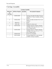
... (Includes Screw and Washer) 1 Screw 1 Washer for cutter screw 1 Trailing Cable (60" Model) (Includes Trailing Cable Clip and screws, Cover Cap, Trailing Ferrite) 1 Trailing Cable (42" Model) (Includes Trailing Cable Clip and screws, Cover Cap, Trailing Ferrite) Lens Cover Assembly 1 Carriage Height Tool (Also Included with the Carriage Assembly) 7-36 HP DesignJet 5000 Series Printers Service Manual Parts and Diagrams Carriage Assembly Reference...
... (Includes Screw and Washer) 1 Screw 1 Washer for cutter screw 1 Trailing Cable (60" Model) (Includes Trailing Cable Clip and screws, Cover Cap, Trailing Ferrite) 1 Trailing Cable (42" Model) (Includes Trailing Cable Clip and screws, Cover Cap, Trailing Ferrite) Lens Cover Assembly 1 Carriage Height Tool (Also Included with the Carriage Assembly) 7-36 HP DesignJet 5000 Series Printers Service Manual Parts and Diagrams Carriage Assembly Reference...
Service Manual
Page 251
... Media Lever Assembly 8-18 Right Hand Trim 8-20 Left Hand Trim 8-22 Back Cover 8-23 Ink Tubes System 8-25 EMC Covers 8-32 Encoder Strip 8-34 Trailing Cable 8-36 Tensioner Assembly 8-42 Carriage Assembly and Belt 8-46 Scan-Axis Motor 8-55 Cutter Assembly 8-58 Ink Supply Station (ISS) 8-62 Air Pressurization System (APS... 8-103 Media Sensor 8-104 Entry Roller 8-106 Center Guide Assembly 8-107 Drive Roller Gear 8-109 Front Platen Assembly 8-110 Center Platen Assembly 8-112 Deflectors 8-114 HP DesignJet 5000 Series Printers Service Manual 8-1
... Media Lever Assembly 8-18 Right Hand Trim 8-20 Left Hand Trim 8-22 Back Cover 8-23 Ink Tubes System 8-25 EMC Covers 8-32 Encoder Strip 8-34 Trailing Cable 8-36 Tensioner Assembly 8-42 Carriage Assembly and Belt 8-46 Scan-Axis Motor 8-55 Cutter Assembly 8-58 Ink Supply Station (ISS) 8-62 Air Pressurization System (APS... 8-103 Media Sensor 8-104 Entry Roller 8-106 Center Guide Assembly 8-107 Drive Roller Gear 8-109 Front Platen Assembly 8-110 Center Platen Assembly 8-112 Deflectors 8-114 HP DesignJet 5000 Series Printers Service Manual 8-1

Service Manual
Page 286
Removal and Installation Trailing Cable Removal WARNING NOTE Switch off the Printer and remove the Power Cord. Refer to Page 8-6. 5. Refer to Page 8-10. 4. Remove the Right Hand Cover - Remove ... on Page 8-4 for information on screw types. 1. Remove the Right Rear Cover - Remove the Top Cover - Unclip and remove the Carriage Cover to access the Trailing Cable in the Carriage. 8-36 HP DesignJet 5000 Series Printers Service Manual
Removal and Installation Trailing Cable Removal WARNING NOTE Switch off the Printer and remove the Power Cord. Refer to Page 8-6. 5. Refer to Page 8-10. 4. Remove the Right Hand Cover - Remove ... on Page 8-4 for information on screw types. 1. Remove the Right Rear Cover - Remove the Top Cover - Unclip and remove the Carriage Cover to access the Trailing Cable in the Carriage. 8-36 HP DesignJet 5000 Series Printers Service Manual

Service Manual
Page 287
HP DesignJet 5000 Series Printers Service Manual 8-37 Carefully disconnect the Trailing Cables (3) from the Trailing Cable Holder. Remove the Trailing Cables from the connectors in the center to release Slide out Removal and Installation 7. Slide the Trailing Cable Guide out of the Carriage. NOTE Remove Trailing Cable Ferrites if they fall into the Carriage n 3 for 60" Model n 1 for 42" Model 8. TIP Press the Trailing Cables firmly in the Carriage PCA. Press down in center to release. 9.
HP DesignJet 5000 Series Printers Service Manual 8-37 Carefully disconnect the Trailing Cables (3) from the Trailing Cable Holder. Remove the Trailing Cables from the connectors in the center to release Slide out Removal and Installation 7. Slide the Trailing Cable Guide out of the Carriage. NOTE Remove Trailing Cable Ferrites if they fall into the Carriage n 3 for 60" Model n 1 for 42" Model 8. TIP Press the Trailing Cables firmly in the Carriage PCA. Press down in center to release. 9.

Service Manual
Page 288
NOTE There is a hole in the Tube Guide to access. 8-38 HP DesignJet 5000 Series Printers Service Manual Remove 2 T-10 screws (Type I) from the Main PCA. 11. NOTE Take care when removing and inserting these screws as they are easily damaged and not easy to access the screw. 12. Removal and Installation 10. Carefully disconnect the Trailing Cable from the Trailing Cable Clip on the left. Remove the T-20 screw (Type C) from the Trailing Cable Clip on the right.
NOTE There is a hole in the Tube Guide to access. 8-38 HP DesignJet 5000 Series Printers Service Manual Remove 2 T-10 screws (Type I) from the Main PCA. 11. NOTE Take care when removing and inserting these screws as they are easily damaged and not easy to access the screw. 12. Removal and Installation 10. Carefully disconnect the Trailing Cable from the Trailing Cable Clip on the left. Remove the T-20 screw (Type C) from the Trailing Cable Clip on the right.

Service Manual
Page 289
Carefully lift the Clips and the Trailing Cable from the Clip on the left as follows: 1. Left Clip locating pin HP DesignJet 5000 Series Printers Service Manual 8-39 Removal and Installation 13. Check edge for damage WARNING When Installing the Trailing Cable, make sure you install it as this will provide a reference point for adjusting the length of Trailing Cable WARNING Do not install damaged Trailing Cables. Install the Trailing Cable starting from the Printer. Installation of the Trailing Cable.
Carefully lift the Clips and the Trailing Cable from the Clip on the left as follows: 1. Left Clip locating pin HP DesignJet 5000 Series Printers Service Manual 8-39 Removal and Installation 13. Check edge for damage WARNING When Installing the Trailing Cable, make sure you install it as this will provide a reference point for adjusting the length of Trailing Cable WARNING Do not install damaged Trailing Cables. Install the Trailing Cable starting from the Printer. Installation of the Trailing Cable.

Service Manual
Page 290
... the right length before installing the screw. 8-40 HP DesignJet 5000 Series Printers Service Manual Insert the Trailing Cable Guide into the Carriage and connect the Trailing Cables. n 3 for 42" Model. 3. Place the Right Trailing Cable Clip in position and the Trailing Cable is in position and adjust the length of the Slot Trailing Cable. Removal and Installation 2. NOTE Remember to pass the...
... the right length before installing the screw. 8-40 HP DesignJet 5000 Series Printers Service Manual Insert the Trailing Cable Guide into the Carriage and connect the Trailing Cables. n 3 for 42" Model. 3. Place the Right Trailing Cable Clip in position and the Trailing Cable is in position and adjust the length of the Slot Trailing Cable. Removal and Installation 2. NOTE Remember to pass the...

Service Manual
Page 291
NOTE Strip will not be visible when inserted correctly. HP DesignJet 5000 Series Printers Service Manual 8-41 The strip should not be visible when installed correctly Make sure the vertical strips on Trailing Cable ends are correctly installed by sliding the carriage along the Printer to the Main ...PCA. NO BUBBLES Removal and Installation TIP Make sure the Trailing Cable is flat on NOTE Check the cable and clips are fully inserted inside the connectors. Connect the Trailing Cables to see if it moves freely. 5. Left Clip locating pin Right Clip ...
NOTE Strip will not be visible when inserted correctly. HP DesignJet 5000 Series Printers Service Manual 8-41 The strip should not be visible when installed correctly Make sure the vertical strips on Trailing Cable ends are correctly installed by sliding the carriage along the Printer to the Main ...PCA. NO BUBBLES Removal and Installation TIP Make sure the Trailing Cable is flat on NOTE Check the cable and clips are fully inserted inside the connectors. Connect the Trailing Cables to see if it moves freely. 5. Left Clip locating pin Right Clip ...

Service Manual
Page 300
Press down in the center to release 16. n 1 for 60" Model. TIP Press the Trailing Cables firmly in center to release. 8-50 HP DesignJet 5000 Series Printers Service Manual NOTE Remove Trailing Cable Ferrites if they fall into the Carriage n 3 for 42" Model. 17. Remove the Trailing Cables from the connectors in the Carriage. Removal and Installation 15. Carefully disconnect the Trailing Cables (3) from the Trailing Cable Holder. Unclip and remove the Carriage Cover to access the Trailing Cable in the Carriage PCA.
Press down in the center to release 16. n 1 for 60" Model. TIP Press the Trailing Cables firmly in center to release. 8-50 HP DesignJet 5000 Series Printers Service Manual NOTE Remove Trailing Cable Ferrites if they fall into the Carriage n 3 for 42" Model. 17. Remove the Trailing Cables from the connectors in the Carriage. Removal and Installation 15. Carefully disconnect the Trailing Cables (3) from the Trailing Cable Holder. Unclip and remove the Carriage Cover to access the Trailing Cable in the Carriage PCA.

Service Manual
Page 301
Slide the Trailing Cable Guide out of the Printer. 20. HP DesignJet 5000 Series Printers Service Manual 8-51 Slide the Carriage (including the Belt) to the left and out of the Carriage. 19. Remove the Belt from the Carriage by releasing it from the retaining clips underneath the Carriage. Slide out Removal and Installation 18.
Slide the Trailing Cable Guide out of the Printer. 20. HP DesignJet 5000 Series Printers Service Manual 8-51 Slide the Carriage (including the Belt) to the left and out of the Carriage. 19. Remove the Belt from the Carriage by releasing it from the retaining clips underneath the Carriage. Slide out Removal and Installation 18.
Service Manual
Page 332
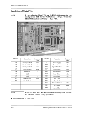
...white white red NOTE When the Main PCA has been reinstalled or replaced, perform the following Service Utility procedure: n Backup EEROM ⇒ Page 4-31. 8-82 HP DesignJet 5000 Series Printers Service Manual Removal and Installation Installation of Main PCA NOTE If you replace the Main PCA and the HDD at the same time...P23 J13 P24 P27 P29 P30 J6 J7 J8 J5 P9 P25 P26 J15 J Position J1 J2 J3 J5 J6 J7 J8 J13 J15 Connection Trailing Cable 3 Trailing Cable 2 Trailing Cable 1 ISS PCA Cable BootROM RAM RAM Media Sensor Parallel Port Connector Color white white white black white -
...white white red NOTE When the Main PCA has been reinstalled or replaced, perform the following Service Utility procedure: n Backup EEROM ⇒ Page 4-31. 8-82 HP DesignJet 5000 Series Printers Service Manual Removal and Installation Installation of Main PCA NOTE If you replace the Main PCA and the HDD at the same time...P23 J13 P24 P27 P29 P30 J6 J7 J8 J5 P9 P25 P26 J15 J Position J1 J2 J3 J5 J6 J7 J8 J13 J15 Connection Trailing Cable 3 Trailing Cable 2 Trailing Cable 1 ISS PCA Cable BootROM RAM RAM Media Sensor Parallel Port Connector Color white white white black white -


