Service Manual
Page 5
... system" 1-17 User message "Power Supply Error #1" 1-17 Cutter Assembly Problems 1-19 Carriage and Scan-Axis Problems 1-20 Media-Axis Problems 1-20 Electronics Problems 1-21 Language Selection is blocked in different HP DesignJet Printers 1-11 Banding at high altitudes 1-10 Printhead Crashes/Smears on...through the Front Panel Menus 1-26 Service Configuration Print 1-37 General Printer Information 1-39 Troubleshooting Take-Up-Reel Problems 1-40 HP DesignJet 5000 Series Printers Service Manual 3 Self Diagnostic Errors 1-4 Solving Image Quality Problems 1-4 The Printer does not Power ON 1-5 ALL...
... system" 1-17 User message "Power Supply Error #1" 1-17 Cutter Assembly Problems 1-19 Carriage and Scan-Axis Problems 1-20 Media-Axis Problems 1-20 Electronics Problems 1-21 Language Selection is blocked in different HP DesignJet Printers 1-11 Banding at high altitudes 1-10 Printhead Crashes/Smears on...through the Front Panel Menus 1-26 Service Configuration Print 1-37 General Printer Information 1-39 Troubleshooting Take-Up-Reel Problems 1-40 HP DesignJet 5000 Series Printers Service Manual 3 Self Diagnostic Errors 1-4 Solving Image Quality Problems 1-4 The Printer does not Power ON 1-5 ALL...
Service Manual
Page 10
...32 Encoder Strip 8-34 Trailing Cable 8-36 Tensioner Assembly 8-42 Carriage Assembly and Belt 8-46 Scan-Axis Motor 8-53 Cutter Assembly 8-56 Ink Supply Station (ISS) 8-60 Air Pressurization System (APS) 8-63 Service Station Assembly 8-65 Drop Detector Assembly 8-68 Hard Disk Drive (HDD) 8-70 LAN... Assembly) 8-90 Pinch-Wheels 8-91 Pinch-Wheel Cam 8-93 Vacuum Fan 8-96 Paper-Axis Motor Assembly 8-98 Booster Fan 8-101 Media Sensor 8-102 Entry Roller 8-104 Center Guide Assembly 8-105 Drive Roller Gear 8-107 Front Platen Assembly 8-108 Center Platen Assembly 8-110 Deflectors 8-112 8 HP DesignJet 5000...
...32 Encoder Strip 8-34 Trailing Cable 8-36 Tensioner Assembly 8-42 Carriage Assembly and Belt 8-46 Scan-Axis Motor 8-53 Cutter Assembly 8-56 Ink Supply Station (ISS) 8-60 Air Pressurization System (APS) 8-63 Service Station Assembly 8-65 Drop Detector Assembly 8-68 Hard Disk Drive (HDD) 8-70 LAN... Assembly) 8-90 Pinch-Wheels 8-91 Pinch-Wheel Cam 8-93 Vacuum Fan 8-96 Paper-Axis Motor Assembly 8-98 Booster Fan 8-101 Media Sensor 8-102 Entry Roller 8-104 Center Guide Assembly 8-105 Drive Roller Gear 8-107 Front Platen Assembly 8-108 Center Platen Assembly 8-110 Deflectors 8-112 8 HP DesignJet 5000...
Service Manual
Page 13
... Take-Up Reel 1-14 Wrinkles and scratches (cockle) on HP Coated and Heavyweight Coated Media. 1-15 Dry Cockle on High Density Prints Using Paper Based Media 1-14 Worm marks (cockle) on part of tubes system" 1-17 User message "Power Supply Error #1" 1-17 Cutter Assembly Problems 1-19 Carriage and Scan-Axis Problems 1-20 Media... Firmware Version Relates to Navigate through the Front Panel Menus 1-26 Service Configuration Print 1-37 General Printer Information 1-39 Troubleshooting Take-Up-Reel Problems 1-40 HP DesignJet 5000 Series Printers Service Manual 1-1
... Take-Up Reel 1-14 Wrinkles and scratches (cockle) on HP Coated and Heavyweight Coated Media. 1-15 Dry Cockle on High Density Prints Using Paper Based Media 1-14 Worm marks (cockle) on part of tubes system" 1-17 User message "Power Supply Error #1" 1-17 Cutter Assembly Problems 1-19 Carriage and Scan-Axis Problems 1-20 Media... Firmware Version Relates to Navigate through the Front Panel Menus 1-26 Service Configuration Print 1-37 General Printer Information 1-39 Troubleshooting Take-Up-Reel Problems 1-40 HP DesignJet 5000 Series Printers Service Manual 1-1

Service Manual
Page 31
... Error Code ffff ffff 03450097 may appear on the front panel, the cutter is automatically disabled, but there is solved in the middle of the Diagnostic Print. As in all DesignJets, the Cutter can happen whenever the Diagnostic Print is disabled in the Front Panel). ...consideration, when Canvas is selected on the front panel. The Cutter does not cut after re-printing the Diagnostic Print, replace the Cutter Assembly ⇒ Page 8-58. n If the Cutter still doesn't cut thick paper (Canvas & Non-HP Media). HP DesignJet 5000 Series Printers Service Manual 1-19 The Printer does not cut ...
... Error Code ffff ffff 03450097 may appear on the front panel, the cutter is automatically disabled, but there is solved in the middle of the Diagnostic Print. As in all DesignJets, the Cutter can happen whenever the Diagnostic Print is disabled in the Front Panel). ...consideration, when Canvas is selected on the front panel. The Cutter does not cut after re-printing the Diagnostic Print, replace the Cutter Assembly ⇒ Page 8-58. n If the Cutter still doesn't cut thick paper (Canvas & Non-HP Media). HP DesignJet 5000 Series Printers Service Manual 1-19 The Printer does not cut ...
Service Manual
Page 232
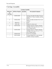
..., Cutter Assembly and Line Sensor) 1 Cutter Assembly (Includes Screw and Washer) 1 Screw 1 Washer for cutter screw 1 Trailing Cable (60" Model) (Includes Trailing Cable Clip and screws, Cover Cap, Trailing Ferrite) 1 Trailing Cable (42" Model) (Includes Trailing Cable Clip and screws, Cover Cap, Trailing Ferrite) Lens Cover Assembly 1 Carriage Height Tool (Also Included with the Carriage Assembly) 7-36 HP DesignJet 5000...
..., Cutter Assembly and Line Sensor) 1 Cutter Assembly (Includes Screw and Washer) 1 Screw 1 Washer for cutter screw 1 Trailing Cable (60" Model) (Includes Trailing Cable Clip and screws, Cover Cap, Trailing Ferrite) 1 Trailing Cable (42" Model) (Includes Trailing Cable Clip and screws, Cover Cap, Trailing Ferrite) Lens Cover Assembly 1 Carriage Height Tool (Also Included with the Carriage Assembly) 7-36 HP DesignJet 5000...
Service Manual
Page 251
... Encoder Strip 8-34 Trailing Cable 8-36 Tensioner Assembly 8-42 Carriage Assembly and Belt 8-46 Scan-Axis Motor 8-55 Cutter Assembly 8-58 Ink Supply Station (ISS) 8-62 Air Pressurization System (APS) 8-65 Service Station Assembly 8-67 Drop Detector Assembly 8-70 Hard Disk Drive (HDD) 8-72 LAN... Assembly) 8-92 Pinch-Wheels 8-93 Pinch-Wheel Cam 8-95 Vacuum Fan 8-98 Paper-Axis Motor Assembly 8-100 Booster Fan 8-103 Media Sensor 8-104 Entry Roller 8-106 Center Guide Assembly 8-107 Drive Roller Gear 8-109 Front Platen Assembly 8-110 Center Platen Assembly 8-112 Deflectors 8-114 HP DesignJet 5000 ...
... Encoder Strip 8-34 Trailing Cable 8-36 Tensioner Assembly 8-42 Carriage Assembly and Belt 8-46 Scan-Axis Motor 8-55 Cutter Assembly 8-58 Ink Supply Station (ISS) 8-62 Air Pressurization System (APS) 8-65 Service Station Assembly 8-67 Drop Detector Assembly 8-70 Hard Disk Drive (HDD) 8-72 LAN... Assembly) 8-92 Pinch-Wheels 8-93 Pinch-Wheel Cam 8-95 Vacuum Fan 8-98 Paper-Axis Motor Assembly 8-100 Booster Fan 8-103 Media Sensor 8-104 Entry Roller 8-106 Center Guide Assembly 8-107 Drive Roller Gear 8-109 Front Platen Assembly 8-110 Center Platen Assembly 8-112 Deflectors 8-114 HP DesignJet 5000 ...

Service Manual
Page 308
Lift up the Carriage Cover and remove ALL the Printheads and close the Carriage Cover. 8-58 HP DesignJet 5000 Series Printers Service Manual Open the Top Cover. 2. Refer to the position shown. 3. Removal and Installation Cutter Assembly Removal WARNING NOTE Switch off the Printer and remove the Power Cord. Pull the Carriage out along the Printer to the table on Page 8-4 for information on screw types. 1.
Lift up the Carriage Cover and remove ALL the Printheads and close the Carriage Cover. 8-58 HP DesignJet 5000 Series Printers Service Manual Open the Top Cover. 2. Refer to the position shown. 3. Removal and Installation Cutter Assembly Removal WARNING NOTE Switch off the Printer and remove the Power Cord. Pull the Carriage out along the Printer to the table on Page 8-4 for information on screw types. 1.

Service Manual
Page 363
... to the Overdrive Wheels. HP DesignJet 5000 Series Printers Service Manual 8-113 n Carriage Height Calibration ⇒ Page 5-18. WARNING When installing the Center Platen Assembly, make sure the foam guides under the Platen are placed in their slots as shown below. Remove the complete Center Platen Assembly (includes the Overdrive Assembly and the Cutter guide). Removal and...
... to the Overdrive Wheels. HP DesignJet 5000 Series Printers Service Manual 8-113 n Carriage Height Calibration ⇒ Page 5-18. WARNING When installing the Center Platen Assembly, make sure the foam guides under the Platen are placed in their slots as shown below. Remove the complete Center Platen Assembly (includes the Overdrive Assembly and the Cutter guide). Removal and...
Service Manual
Page 396
... 8-113 Parts List 7-40 Removal 8-112 Cleaning General 9-10 Cockle 1-15 Color Accuracy Configuration 6-18 Consistency problems 6-17 Color differences 1-11 Cooling Fans Removal 8-90 Cutter Assembly Parts List 7-36 Problems 1-19 Removal 8-58 D Deflectors Parts List 7-44 Removal 8-114 Diagnostic Print 6-4 No Printing Defects 6-16 Diagnostic Print Utility 4-34 Diagnostics ... Removal 8-34 Entry Roller Parts List 7-44 Removal 8-106 Extension Cover Removal 8-17 F Firmware Upgrade Problems 1-23 Firmware Upgrade CD 7-52 Firmware Upgrades 9-11 Index-2 HP DesignJet 5000 Series Printers Service Manual
... 8-113 Parts List 7-40 Removal 8-112 Cleaning General 9-10 Cockle 1-15 Color Accuracy Configuration 6-18 Consistency problems 6-17 Color differences 1-11 Cooling Fans Removal 8-90 Cutter Assembly Parts List 7-36 Problems 1-19 Removal 8-58 D Deflectors Parts List 7-44 Removal 8-114 Diagnostic Print 6-4 No Printing Defects 6-16 Diagnostic Print Utility 4-34 Diagnostics ... Removal 8-34 Entry Roller Parts List 7-44 Removal 8-106 Extension Cover Removal 8-17 F Firmware Upgrade Problems 1-23 Firmware Upgrade CD 7-52 Firmware Upgrades 9-11 Index-2 HP DesignJet 5000 Series Printers Service Manual
Service Manual
Page 399
... 6-19 Parts List 7-32 Color to Color Alignment 6-19 HP DesignJet 5000 Series Printers Service Manual Index-5 Index Parts List Removal 8-86 APS Assembly 7-22 Main Back Cover 7-10 Parts List 7-32 Booster Fan 7-16 Removal 8-79 Carriage Assembly 7-36 Pinch-Wheel Cam Center Guide 7-44 Installation 8-97 Cutter Assembly 7-36 Removal 8-95 Deflectors 7-44 Pinch-Wheels...
... 6-19 Parts List 7-32 Color to Color Alignment 6-19 HP DesignJet 5000 Series Printers Service Manual Index-5 Index Parts List Removal 8-86 APS Assembly 7-22 Main Back Cover 7-10 Parts List 7-32 Booster Fan 7-16 Removal 8-79 Carriage Assembly 7-36 Pinch-Wheel Cam Center Guide 7-44 Installation 8-97 Cutter Assembly 7-36 Removal 8-95 Deflectors 7-44 Pinch-Wheels...

Service Manual
Page 400
...21 R Removal Air Pressurization System 8-65 Back Cover 8-23 Booster Fan 8-103 Carriage Assembly and Belt 8-46 Center Guide Assembly 8-107 Center Platen Assembly 8-112 Cooling Fans 8-90 Cutter Assembly 8-58 Deflectors 8-114 DIMM's 8-75 Drive Roller Gear 8-109 Drop Detector Assembly 8-70 Electronics Module 8-92 Electronics Module Cover 8-77 EMC Covers 8-32 Encoder Strip... Lubrification 9-7 S Scan Axis Test 4-10 Scan-Axis Calibration 5-7 Scan-Axis Motor Installation 8-58 Parts List 7-20 Removal 8-55 Scheduled Maintenance 9-2 Scratches 1-15 Index-6 HP DesignJet 5000 Series Printers Service Manual
...21 R Removal Air Pressurization System 8-65 Back Cover 8-23 Booster Fan 8-103 Carriage Assembly and Belt 8-46 Center Guide Assembly 8-107 Center Platen Assembly 8-112 Cooling Fans 8-90 Cutter Assembly 8-58 Deflectors 8-114 DIMM's 8-75 Drive Roller Gear 8-109 Drop Detector Assembly 8-70 Electronics Module 8-92 Electronics Module Cover 8-77 EMC Covers 8-32 Encoder Strip... Lubrification 9-7 S Scan Axis Test 4-10 Scan-Axis Calibration 5-7 Scan-Axis Motor Installation 8-58 Parts List 7-20 Removal 8-55 Scheduled Maintenance 9-2 Scratches 1-15 Index-6 HP DesignJet 5000 Series Printers Service Manual


