Service Manual
Page 10
... 8-20 Left Hand Trim 8-22 Back Cover 8-23 Ink Tubes System 8-25 EMC Covers 8-32 Encoder Strip 8-34 Trailing Cable 8-36 Tensioner Assembly 8-42 Carriage Assembly and Belt 8-46 Scan-Axis Motor 8-53 Cutter Assembly 8-56 Ink Supply Station (ISS) 8-60 Air Pressurization System (APS) 8-63 Service Station Assembly 8-65 Drop Detector... 8-101 Media Sensor 8-102 Entry Roller 8-104 Center Guide Assembly 8-105 Drive Roller Gear 8-107 Front Platen Assembly 8-108 Center Platen Assembly 8-110 Deflectors 8-112 8 HP DesignJet 5000 Series Printers Service Manual
... 8-20 Left Hand Trim 8-22 Back Cover 8-23 Ink Tubes System 8-25 EMC Covers 8-32 Encoder Strip 8-34 Trailing Cable 8-36 Tensioner Assembly 8-42 Carriage Assembly and Belt 8-46 Scan-Axis Motor 8-53 Cutter Assembly 8-56 Ink Supply Station (ISS) 8-60 Air Pressurization System (APS) 8-63 Service Station Assembly 8-65 Drop Detector... 8-101 Media Sensor 8-102 Entry Roller 8-104 Center Guide Assembly 8-105 Drive Roller Gear 8-107 Front Platen Assembly 8-108 Center Platen Assembly 8-110 Deflectors 8-112 8 HP DesignJet 5000 Series Printers Service Manual
Service Manual
Page 11
... Wiper 9-6 Roller Lubrification Kit 9-7 Slider Rods Lubrification Kit 9-8 Cleaning the Platen 9-9 Moisture on the Printer 9-10 Noisy Carriage Bushing 9-10 Belt Swelling 9-10 General Cleaning 9-10 Firmware Upgrade 9-11 Functional Overview 10-1 Introduction 10-2 Electrical System 10-2 Front Panel 10-3 Scan Axis 10-3 Paper Axis 10-4 ...-8 Service Station 10-9 Print Head Cleaner (PHC) 10-9 Printer Specifications 10-10 Printable Area 10-13 Interface Specifications 10-13 Glossary Index Table of Contents HP DesignJet 5000 Series Printers Service Manual 9
... Wiper 9-6 Roller Lubrification Kit 9-7 Slider Rods Lubrification Kit 9-8 Cleaning the Platen 9-9 Moisture on the Printer 9-10 Noisy Carriage Bushing 9-10 Belt Swelling 9-10 General Cleaning 9-10 Firmware Upgrade 9-11 Functional Overview 10-1 Introduction 10-2 Electrical System 10-2 Front Panel 10-3 Scan Axis 10-3 Paper Axis 10-4 ...-8 Service Station 10-9 Print Head Cleaner (PHC) 10-9 Printer Specifications 10-10 Printable Area 10-13 Interface Specifications 10-13 Glossary Index Table of Contents HP DesignJet 5000 Series Printers Service Manual 9
Service Manual
Page 20
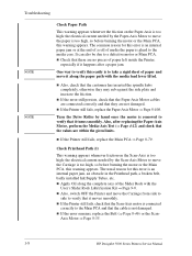
... the Belt (⇒ Page 8-46) or the Scan- n If the Printer still fails, replace the Paper-Axis Motor ⇒ Page 8-100. Axis Motor ⇒ Page 8-55. 1-8 HP DesignJet 5000 Series Printers Service Manual n Also, check that it turns smoothly. n Also, switch OFF the Printer and move the Carriage from side... spindle hubs completely, otherwise they are within the given limits. Also, after a paper jam. It can also be due to move the Carriage is not damaged. One way to verify this easily is to take a rigid sheet of the Slider Rods with the media load lever lifted...
... the Belt (⇒ Page 8-46) or the Scan- n If the Printer still fails, replace the Paper-Axis Motor ⇒ Page 8-100. Axis Motor ⇒ Page 8-55. 1-8 HP DesignJet 5000 Series Printers Service Manual n Also, check that it turns smoothly. n Also, switch OFF the Printer and move the Carriage from side... spindle hubs completely, otherwise they are within the given limits. Also, after a paper jam. It can also be due to move the Carriage is not damaged. One way to verify this easily is to take a rigid sheet of the Slider Rods with the media load lever lifted...

Service Manual
Page 107
...8-55. 4. If necessary, replace the Carriage Belt ⇒ Page 8-46. n All values reported in the test. To check if the values displayed after each one: 1. Clean Slider Rods and Apply Oil along the complete axis of the Printer. HP DesignJet 5000 Series Printers Service Manual 4-11 Replace the ...Tensioner Assembly ⇒ Page 8-42. 5. NOTE Service Tests and Utilities Report the values to the nearest HP Response Center or HP Support Office to determine whether values are not...
...8-55. 4. If necessary, replace the Carriage Belt ⇒ Page 8-46. n All values reported in the test. To check if the values displayed after each one: 1. Clean Slider Rods and Apply Oil along the complete axis of the Printer. HP DesignJet 5000 Series Printers Service Manual 4-11 Replace the ...Tensioner Assembly ⇒ Page 8-42. 5. NOTE Service Tests and Utilities Report the values to the nearest HP Response Center or HP Support Office to determine whether values are not...

Service Manual
Page 149
... hand side of the Printer for correct calibration. HP DesignJet 5000 Series Printers Service Manual 5-19 NOTE Service Calibrations During the Carriage Height Calibration procedure the Carriage Assembly has to Page 8-23. 3. Remove the Top Cover - Make sure that the Carriage Assembly is only ever moved by pulling the Belt and never by direct contact with the...
... hand side of the Printer for correct calibration. HP DesignJet 5000 Series Printers Service Manual 5-19 NOTE Service Calibrations During the Carriage Height Calibration procedure the Carriage Assembly has to Page 8-23. 3. Remove the Top Cover - Make sure that the Carriage Assembly is only ever moved by pulling the Belt and never by direct contact with the...

Service Manual
Page 151
... a scraping sound is positioned when printing), move the Carriage Assembly back and forth along the length of the Printer. HP DesignJet 5000 Series Printers Service Manual 5-21 Loosen the two T10 screws at the back of the paper is heard. NOTE Service Calibrations 7. Using the Belt, and beginning on the left hand side of the...
... a scraping sound is positioned when printing), move the Carriage Assembly back and forth along the length of the Printer. HP DesignJet 5000 Series Printers Service Manual 5-21 Loosen the two T10 screws at the back of the paper is heard. NOTE Service Calibrations 7. Using the Belt, and beginning on the left hand side of the...
Service Manual
Page 251
... 8-20 Left Hand Trim 8-22 Back Cover 8-23 Ink Tubes System 8-25 EMC Covers 8-32 Encoder Strip 8-34 Trailing Cable 8-36 Tensioner Assembly 8-42 Carriage Assembly and Belt 8-46 Scan-Axis Motor 8-55 Cutter Assembly 8-58 Ink Supply Station (ISS) 8-62 Air Pressurization System (APS) 8-65 Service Station Assembly 8-67 Drop Detector... 8-103 Media Sensor 8-104 Entry Roller 8-106 Center Guide Assembly 8-107 Drive Roller Gear 8-109 Front Platen Assembly 8-110 Center Platen Assembly 8-112 Deflectors 8-114 HP DesignJet 5000 Series Printers Service Manual 8-1
... 8-20 Left Hand Trim 8-22 Back Cover 8-23 Ink Tubes System 8-25 EMC Covers 8-32 Encoder Strip 8-34 Trailing Cable 8-36 Tensioner Assembly 8-42 Carriage Assembly and Belt 8-46 Scan-Axis Motor 8-55 Cutter Assembly 8-58 Ink Supply Station (ISS) 8-62 Air Pressurization System (APS) 8-65 Service Station Assembly 8-67 Drop Detector... 8-103 Media Sensor 8-104 Entry Roller 8-106 Center Guide Assembly 8-107 Drive Roller Gear 8-109 Front Platen Assembly 8-110 Center Platen Assembly 8-112 Deflectors 8-114 HP DesignJet 5000 Series Printers Service Manual 8-1

Service Manual
Page 295
Insert Encoder Strip Encoder Sensor HP DesignJet 5000 Series Printers Service Manual 8-45 When installing the Encoder Strip, make sure it is inserted in the Encoder Sensor on the rear of Tensioner Assembly NOTE Before installation, clean and oil the Slider Rods using the User's Slider Rods Lubrification Kit (Refer to twist the Belt when installing the Tensioner Assembly. Removal and Installation Installation of the Carriage Assembly as shown below. WARNING WARNING Be careful not to Page 9-8).
Insert Encoder Strip Encoder Sensor HP DesignJet 5000 Series Printers Service Manual 8-45 When installing the Encoder Strip, make sure it is inserted in the Encoder Sensor on the rear of Tensioner Assembly NOTE Before installation, clean and oil the Slider Rods using the User's Slider Rods Lubrification Kit (Refer to twist the Belt when installing the Tensioner Assembly. Removal and Installation Installation of the Carriage Assembly as shown below. WARNING WARNING Be careful not to Page 9-8).

Service Manual
Page 296
Removal and Installation Carriage Assembly and Belt NOTE Please be replaced by removing the 2 T-8 screws. Remove the Right Rear Cover - Refer to break the Encoder Guide. If necessary, it , remove the 2 T-8 screws at the rear of the Carriage and install the new Encoder Guide. ... To replace it can be very careful when handling the Encoder Guide at the rear of the Carriage Assembly. Remove the Right Hand Cover - Pull out Printhead Cleaner Carriage. 8-46 HP DesignJet 5000 Series Printers Service Manual Refer to Page 8-6. 2. If you break the Encoder Guide, a spare...
Removal and Installation Carriage Assembly and Belt NOTE Please be replaced by removing the 2 T-8 screws. Remove the Right Rear Cover - Refer to break the Encoder Guide. If necessary, it , remove the 2 T-8 screws at the rear of the Carriage and install the new Encoder Guide. ... To replace it can be very careful when handling the Encoder Guide at the rear of the Carriage Assembly. Remove the Right Hand Cover - Pull out Printhead Cleaner Carriage. 8-46 HP DesignJet 5000 Series Printers Service Manual Refer to Page 8-6. 2. If you break the Encoder Guide, a spare...

Service Manual
Page 301
Remove the Belt from the Carriage by releasing it from the retaining clips underneath the Carriage. Slide out Removal and Installation 18. Slide the Trailing Cable Guide out of the Printer. 20. HP DesignJet 5000 Series Printers Service Manual 8-51 Slide the Carriage (including the Belt) to the left and out of the Carriage. 19.
Remove the Belt from the Carriage by releasing it from the retaining clips underneath the Carriage. Slide out Removal and Installation 18. Slide the Trailing Cable Guide out of the Printer. 20. HP DesignJet 5000 Series Printers Service Manual 8-51 Slide the Carriage (including the Belt) to the left and out of the Carriage. 19.

Service Manual
Page 302
Line up the Carriage Guide, on the underside of the Carriage indicates position and direction. 2. Insert belt as follows: 1. TIP An arrow on the bottom of the carriage, with the Slider Rods on the underside of Carriage and Belt Before installation, clean and oil the Slider Rods using the User's Slider Rods Lubrification Kit (Refer to the User's Guide). WARNING Make sure you install the Carriage Assembly and Belt as indicated on the Printer. 8-52 HP DesignJet 5000 Series Printers Service Manual Removal and Installation NOTE Installation of Carriage.
Line up the Carriage Guide, on the underside of the Carriage indicates position and direction. 2. Insert belt as follows: 1. TIP An arrow on the bottom of the carriage, with the Slider Rods on the underside of Carriage and Belt Before installation, clean and oil the Slider Rods using the User's Slider Rods Lubrification Kit (Refer to the User's Guide). WARNING Make sure you install the Carriage Assembly and Belt as indicated on the Printer. 8-52 HP DesignJet 5000 Series Printers Service Manual Removal and Installation NOTE Installation of Carriage.

Service Manual
Page 307
From the right-hand side, lift the Tensioner Belt off the Scan-Axis Motor. 10. Lower the Scan-Axis Motor and remove from the Printer. Installation of the Carriage Assembly. While supporting the Scan-Axis Motor, remove 2 T-15 screws (Type B). 11. WARNING When installing the Encoder Strip, make sure it is inserted in... Motor NOTE Before installation, clean and oil the Slider Rods using the User's Slider Rods Lubrification Kit (Refer to Page 9-8). Insert Encoder Strip Encoder Sensor HP DesignJet 5000 Series Printers Service Manual 8-57 Removal and Installation 9.
From the right-hand side, lift the Tensioner Belt off the Scan-Axis Motor. 10. Lower the Scan-Axis Motor and remove from the Printer. Installation of the Carriage Assembly. While supporting the Scan-Axis Motor, remove 2 T-15 screws (Type B). 11. WARNING When installing the Encoder Strip, make sure it is inserted in... Motor NOTE Before installation, clean and oil the Slider Rods using the User's Slider Rods Lubrification Kit (Refer to Page 9-8). Insert Encoder Strip Encoder Sensor HP DesignJet 5000 Series Printers Service Manual 8-57 Removal and Installation 9.

Service Manual
Page 365
Preventive Maintenance 9 Introduction 9-2 Service Preventive Maintenance 9-2 Warning/Stop Triggers 9-3 Routine Maintenance 9-5 Lens Maintenance 9-5 Carriage Interconnect Wiper 9-6 Roller Lubrification Kit 9-7 Slider Rods Lubrification Kit 9-8 Cleaning the Platen 9-9 Noisy Carriage Bushing 9-10 Belt Swelling 9-10 General Cleaning 9-10 Firmware Upgrade 9-11 HP DesignJet 5000 Series Printers Service Manual 9-1
Preventive Maintenance 9 Introduction 9-2 Service Preventive Maintenance 9-2 Warning/Stop Triggers 9-3 Routine Maintenance 9-5 Lens Maintenance 9-5 Carriage Interconnect Wiper 9-6 Roller Lubrification Kit 9-7 Slider Rods Lubrification Kit 9-8 Cleaning the Platen 9-9 Noisy Carriage Bushing 9-10 Belt Swelling 9-10 General Cleaning 9-10 Firmware Upgrade 9-11 HP DesignJet 5000 Series Printers Service Manual 9-1

Service Manual
Page 374
...Carriage, and from moisture condensation, turn the Printer Off, and, using it free of dust accumulation, ink, and other contamination. see the User's Guide. Do not use the Printer in an environment between 20% and 80% relative humidity. Use a mild soap and water solution if necessary. Belt... you need to do this - General Cleaning To maintain the Printer in their bags with a soft lint-free cloth. 9-10 HP DesignJet 5000 Series Printers Service Manual To recover from the Slider Rods along which the bushing moves. Preventive Maintenance Moisture on the Printer Users should...
...Carriage, and from moisture condensation, turn the Printer Off, and, using it free of dust accumulation, ink, and other contamination. see the User's Guide. Do not use the Printer in an environment between 20% and 80% relative humidity. Use a mild soap and water solution if necessary. Belt... you need to do this - General Cleaning To maintain the Printer in their bags with a soft lint-free cloth. 9-10 HP DesignJet 5000 Series Printers Service Manual To recover from the Slider Rods along which the bushing moves. Preventive Maintenance Moisture on the Printer Users should...

Service Manual
Page 379
... the LED Sensor on top of the display are : n Scan-Axis Motor - determines the position of the Carriage using the Belt. The display has an LED backlight to improve its position with respect to the media. Speed). n 1 key on the upper right corner is used to ... at the same time. The display is a 128 x 64 pixel graphic LCD and can also be adjusted. Quality, Productivity or Max. The contrast of the Belt. Functional Overview Front Panel The Front Panel is used to set the Printer to Standby mode. n Tensioner - HP DesignJet 5000 Series Printers Service Manual 10-3
... the LED Sensor on top of the display are : n Scan-Axis Motor - determines the position of the Carriage using the Belt. The display has an LED backlight to improve its position with respect to the media. Speed). n 1 key on the upper right corner is used to ... at the same time. The display is a 128 x 64 pixel graphic LCD and can also be adjusted. Quality, Productivity or Max. The contrast of the Belt. Functional Overview Front Panel The Front Panel is used to set the Printer to Standby mode. n Tensioner - HP DesignJet 5000 Series Printers Service Manual 10-3
Service Manual
Page 396
Index 2006 5-33 2007 5-33 2008 5-33 2101 (through to 2607) 5-34 Calibrations Service 5-3 Carriage Assembly and Belt Installation 8-52 Parts List 7-36 Removal 8-46 Carriage Height Calibration 5-18 Carriage Interconnect Wiper 9-6 Carriage Usage Cycles 9-3 Center Guide Assembly Parts List 7-44 Removal 8-107 Center Platen Assembly Installation 8-113 Parts List 7-40 Removal 8-112 ... Entry Roller Parts List 7-44 Removal 8-106 Extension Cover Removal 8-17 F Firmware Upgrade Problems 1-23 Firmware Upgrade CD 7-52 Firmware Upgrades 9-11 Index-2 HP DesignJet 5000 Series Printers Service Manual
Index 2006 5-33 2007 5-33 2008 5-33 2101 (through to 2607) 5-34 Calibrations Service 5-3 Carriage Assembly and Belt Installation 8-52 Parts List 7-36 Removal 8-46 Carriage Height Calibration 5-18 Carriage Interconnect Wiper 9-6 Carriage Usage Cycles 9-3 Center Guide Assembly Parts List 7-44 Removal 8-107 Center Platen Assembly Installation 8-113 Parts List 7-40 Removal 8-112 ... Entry Roller Parts List 7-44 Removal 8-106 Extension Cover Removal 8-17 F Firmware Upgrade Problems 1-23 Firmware Upgrade CD 7-52 Firmware Upgrades 9-11 Index-2 HP DesignJet 5000 Series Printers Service Manual
Service Manual
Page 397
... Station (ISS) PCA Removal 8-86 Ink Tubes System Installation 8-30 Parts List 7-24 Removal 8-25 Installation Air Pressurization System 8-66 Carriage Assembly and Belt 8-52 Center Platen Assembly 8-113 Encoder Strip 8-35 Hard Disk Drive 8-73 Ink Supply Station 8-64 Ink Tubes System 8-30 Left...8-45 Trailing Cable 8-39 Vacuum Fan 8-99 Interface Specifications 10-13 ISS see Ink Supply Station ISS PCA see Ink Supply Station PCA HP DesignJet 5000 Series Printers Service Manual Index-3 Firmware Version 1-2 Front Panel Assembly Parts List 7-6 Removal 8-14 Front Panel Display 3-6 Front Platen Assembly ...
... Station (ISS) PCA Removal 8-86 Ink Tubes System Installation 8-30 Parts List 7-24 Removal 8-25 Installation Air Pressurization System 8-66 Carriage Assembly and Belt 8-52 Center Platen Assembly 8-113 Encoder Strip 8-35 Hard Disk Drive 8-73 Ink Supply Station 8-64 Ink Tubes System 8-30 Left...8-45 Trailing Cable 8-39 Vacuum Fan 8-99 Interface Specifications 10-13 ISS see Ink Supply Station ISS PCA see Ink Supply Station PCA HP DesignJet 5000 Series Printers Service Manual Index-3 Firmware Version 1-2 Front Panel Assembly Parts List 7-6 Removal 8-14 Front Panel Display 3-6 Front Platen Assembly ...

Service Manual
Page 400
... 1-10 Vertical Banding 6-20 Vertical Line Straightness 6-13 Warped Lines on Media 6-21 R Removal Air Pressurization System 8-65 Back Cover 8-23 Booster Fan 8-103 Carriage Assembly and Belt 8-46 Center Guide Assembly 8-107 Center Platen Assembly 8-112 Cooling Fans 8-90 Cutter Assembly 8-58 Deflectors 8-114 DIMM's 8-75 Drive Roller Gear 8-109 Drop... 8-16 Roller Lubrification 9-7 S Scan Axis Test 4-10 Scan-Axis Calibration 5-7 Scan-Axis Motor Installation 8-58 Parts List 7-20 Removal 8-55 Scheduled Maintenance 9-2 Scratches 1-15 Index-6 HP DesignJet 5000 Series Printers Service Manual
... 1-10 Vertical Banding 6-20 Vertical Line Straightness 6-13 Warped Lines on Media 6-21 R Removal Air Pressurization System 8-65 Back Cover 8-23 Booster Fan 8-103 Carriage Assembly and Belt 8-46 Center Guide Assembly 8-107 Center Platen Assembly 8-112 Cooling Fans 8-90 Cutter Assembly 8-58 Deflectors 8-114 DIMM's 8-75 Drive Roller Gear 8-109 Drop... 8-16 Roller Lubrification 9-7 S Scan Axis Test 4-10 Scan-Axis Calibration 5-7 Scan-Axis Motor Installation 8-58 Parts List 7-20 Removal 8-55 Scheduled Maintenance 9-2 Scratches 1-15 Index-6 HP DesignJet 5000 Series Printers Service Manual


