Service Manual
Page 10
... Hand Trim 8-22 Back Cover 8-23 Ink Tubes System 8-25 EMC Covers 8-32 Encoder Strip 8-34 Trailing Cable 8-36 Tensioner Assembly 8-42 Carriage Assembly and Belt 8-46 Scan-Axis Motor 8-53 Cutter Assembly 8-56 Ink Supply Station (ISS) 8-60 Air Pressurization System (APS) 8-63 Service Station Assembly 8-65 Drop Detector Assembly... 8-101 Media Sensor 8-102 Entry Roller 8-104 Center Guide Assembly 8-105 Drive Roller Gear 8-107 Front Platen Assembly 8-108 Center Platen Assembly 8-110 Deflectors 8-112 8 HP DesignJet 5000 Series Printers Service Manual
... Hand Trim 8-22 Back Cover 8-23 Ink Tubes System 8-25 EMC Covers 8-32 Encoder Strip 8-34 Trailing Cable 8-36 Tensioner Assembly 8-42 Carriage Assembly and Belt 8-46 Scan-Axis Motor 8-53 Cutter Assembly 8-56 Ink Supply Station (ISS) 8-60 Air Pressurization System (APS) 8-63 Service Station Assembly 8-65 Drop Detector Assembly... 8-101 Media Sensor 8-102 Entry Roller 8-104 Center Guide Assembly 8-105 Drive Roller Gear 8-107 Front Platen Assembly 8-108 Center Platen Assembly 8-110 Deflectors 8-112 8 HP DesignJet 5000 Series Printers Service Manual
Service Manual
Page 11
... 9-5 Lens Maintenance 9-5 Carriage Interconnect Wiper 9-6 Roller Lubrification Kit 9-7 Slider Rods Lubrification Kit 9-8 Cleaning the Platen 9-9 Moisture on the Printer 9-10 Noisy Carriage Bushing 9-10 Belt Swelling 9-10 General Cleaning 9-10 Firmware Upgrade 9-11 Functional Overview 10-1 Introduction 10-2 Electrical System 10-2 Front Panel 10-3 Scan Axis 10-3 Paper Axis 10... Service Station 10-9 Print Head Cleaner (PHC) 10-9 Printer Specifications 10-10 Printable Area 10-13 Interface Specifications 10-13 Glossary Index Table of Contents HP DesignJet 5000 Series Printers Service Manual 9
... 9-5 Lens Maintenance 9-5 Carriage Interconnect Wiper 9-6 Roller Lubrification Kit 9-7 Slider Rods Lubrification Kit 9-8 Cleaning the Platen 9-9 Moisture on the Printer 9-10 Noisy Carriage Bushing 9-10 Belt Swelling 9-10 General Cleaning 9-10 Firmware Upgrade 9-11 Functional Overview 10-1 Introduction 10-2 Electrical System 10-2 Front Panel 10-3 Scan Axis 10-3 Paper Axis 10... Service Station 10-9 Print Head Cleaner (PHC) 10-9 Printer Specifications 10-10 Printable Area 10-13 Interface Specifications 10-13 Glossary Index Table of Contents HP DesignJet 5000 Series Printers Service Manual 9
Service Manual
Page 20
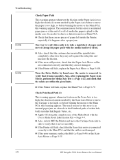
...motor is removed to verify that there are not damaged. n If the error remains, replace the Belt (⇒ Page 8-46) or the Scan- Axis Motor ⇒ Page 8-55. 1-8 HP DesignJet 5000 Series Printers Service Manual n Check that it turns smoothly. The usual reason for this error is an... internal paper jam, an obstacle in the Printhead path, a broken belt, badly installed Ink Supply Tubes, etc. n Also, switch OFF ...
...motor is removed to verify that there are not damaged. n If the error remains, replace the Belt (⇒ Page 8-46) or the Scan- Axis Motor ⇒ Page 8-55. 1-8 HP DesignJet 5000 Series Printers Service Manual n Check that it turns smoothly. The usual reason for this error is an... internal paper jam, an obstacle in the Printhead path, a broken belt, badly installed Ink Supply Tubes, etc. n Also, switch OFF ...

Service Manual
Page 107
... ready: n Model and Serial Number of the Slider Rods with the User's Slider Rods Lubrification Kit ⇒ Page 9-8. 2. Check the Carriage Belt for excessive wear. n The Service Configuration Print ⇒ Page 1-37. Replace the Scan-Axis Motor ⇒ Page 8-55. 4. n All values reported in the test. HP DesignJet 5000 Series Printers Service Manual 4-11
... ready: n Model and Serial Number of the Slider Rods with the User's Slider Rods Lubrification Kit ⇒ Page 9-8. 2. Check the Carriage Belt for excessive wear. n The Service Configuration Print ⇒ Page 1-37. Replace the Scan-Axis Motor ⇒ Page 8-55. 4. n All values reported in the test. HP DesignJet 5000 Series Printers Service Manual 4-11

Service Manual
Page 149
Refer to Page 8-23. 3. Refer to Page 8-5. 2. Correct: move using the Belt. Open the Carriage Cover on the left hand side of the Printer for correct calibration. Remove the Back Cover - Incorrect: never move using Carriage Assembly. Refer to Page 8-32. 4. Figure 2: 1. HP DesignJet 5000 Series Printers Service Manual 5-19 NOTE Service Calibrations During the...
Refer to Page 8-23. 3. Refer to Page 8-5. 2. Correct: move using the Belt. Open the Carriage Cover on the left hand side of the Printer for correct calibration. Remove the Back Cover - Incorrect: never move using Carriage Assembly. Refer to Page 8-32. 4. Figure 2: 1. HP DesignJet 5000 Series Printers Service Manual 5-19 NOTE Service Calibrations During the...

Service Manual
Page 151
... Carriage Assembly. NOTE Service Calibrations 7. Using the Belt, and beginning on the left hand side of the starting position (where the left hand edge of the paper is heard. The screws should not be removed. 8. Loosen the two T10 screws at the back of the Printer. HP DesignJet 5000 Series Printers Service Manual 5-21
... Carriage Assembly. NOTE Service Calibrations 7. Using the Belt, and beginning on the left hand side of the starting position (where the left hand edge of the paper is heard. The screws should not be removed. 8. Loosen the two T10 screws at the back of the Printer. HP DesignJet 5000 Series Printers Service Manual 5-21

Service Manual
Page 234
Tensioner Assembly and Encoder Strip HP Part Number Quantity Description/Comments C6090-60088 0515-2248 C6095-60183 C6090-60072 C6095-60185 C6090-60059 0535-0031 3050-0026 1 Tensioner Assembly (Includes Pulley Assembly, Pulley Spring, Wedge and Actuator Arm) 1 Screw 1 Belt (60" Model) 1 Belt (42" Model) 1 Encoder Strip (60" Model) 1 Encoder Strip (42" Model) 2 Nut 2 Washer 7-38 HP DesignJet 5000 Series Printers Service Manual Parts and Diagrams Tensioner Assembly and Encoder Strip Reference on Drawing 1 2 3 4 5 -
Tensioner Assembly and Encoder Strip HP Part Number Quantity Description/Comments C6090-60088 0515-2248 C6095-60183 C6090-60072 C6095-60185 C6090-60059 0535-0031 3050-0026 1 Tensioner Assembly (Includes Pulley Assembly, Pulley Spring, Wedge and Actuator Arm) 1 Screw 1 Belt (60" Model) 1 Belt (42" Model) 1 Encoder Strip (60" Model) 1 Encoder Strip (42" Model) 2 Nut 2 Washer 7-38 HP DesignJet 5000 Series Printers Service Manual Parts and Diagrams Tensioner Assembly and Encoder Strip Reference on Drawing 1 2 3 4 5 -
Service Manual
Page 251
... Hand Trim 8-22 Back Cover 8-23 Ink Tubes System 8-25 EMC Covers 8-32 Encoder Strip 8-34 Trailing Cable 8-36 Tensioner Assembly 8-42 Carriage Assembly and Belt 8-46 Scan-Axis Motor 8-55 Cutter Assembly 8-58 Ink Supply Station (ISS) 8-62 Air Pressurization System (APS) 8-65 Service Station Assembly 8-67 Drop Detector Assembly... 8-103 Media Sensor 8-104 Entry Roller 8-106 Center Guide Assembly 8-107 Drive Roller Gear 8-109 Front Platen Assembly 8-110 Center Platen Assembly 8-112 Deflectors 8-114 HP DesignJet 5000 Series Printers Service Manual 8-1
... Hand Trim 8-22 Back Cover 8-23 Ink Tubes System 8-25 EMC Covers 8-32 Encoder Strip 8-34 Trailing Cable 8-36 Tensioner Assembly 8-42 Carriage Assembly and Belt 8-46 Scan-Axis Motor 8-55 Cutter Assembly 8-58 Ink Supply Station (ISS) 8-62 Air Pressurization System (APS) 8-65 Service Station Assembly 8-67 Drop Detector Assembly... 8-103 Media Sensor 8-104 Entry Roller 8-106 Center Guide Assembly 8-107 Drive Roller Gear 8-109 Front Platen Assembly 8-110 Center Platen Assembly 8-112 Deflectors 8-114 HP DesignJet 5000 Series Printers Service Manual 8-1

Service Manual
Page 293
Using a screwdriver, fully tighten the Spring Release Screw to release the tension on the Belt. 6. Remove 1 T-15 screw (Type L) from the Tensioner Assembly. From the right-hand side, lift the Tensioner Belt off the Scan-Axis Motor. 7. HP DesignJet 5000 Series Printers Service Manual 8-43 TTigighhtetennscscrreeww Removal and Installation 5.
Using a screwdriver, fully tighten the Spring Release Screw to release the tension on the Belt. 6. Remove 1 T-15 screw (Type L) from the Tensioner Assembly. From the right-hand side, lift the Tensioner Belt off the Scan-Axis Motor. 7. HP DesignJet 5000 Series Printers Service Manual 8-43 TTigighhtetennscscrreeww Removal and Installation 5.

Service Manual
Page 294
Remove the Tensioner Assembly from the left side. 9. Removal and Installation 8. Remove the Belt Wheel on the left -hand side. 8-44 HP DesignJet 5000 Series Printers Service Manual
Remove the Tensioner Assembly from the left side. 9. Removal and Installation 8. Remove the Belt Wheel on the left -hand side. 8-44 HP DesignJet 5000 Series Printers Service Manual

Service Manual
Page 295
Removal and Installation Installation of the Carriage Assembly as shown below. When installing the Encoder Strip, make sure it is inserted in the Encoder Sensor on the rear of Tensioner Assembly NOTE Before installation, clean and oil the Slider Rods using the User's Slider Rods Lubrification Kit (Refer to twist the Belt when installing the Tensioner Assembly. Insert Encoder Strip Encoder Sensor HP DesignJet 5000 Series Printers Service Manual 8-45 WARNING WARNING Be careful not to Page 9-8).
Removal and Installation Installation of the Carriage Assembly as shown below. When installing the Encoder Strip, make sure it is inserted in the Encoder Sensor on the rear of Tensioner Assembly NOTE Before installation, clean and oil the Slider Rods using the User's Slider Rods Lubrification Kit (Refer to twist the Belt when installing the Tensioner Assembly. Insert Encoder Strip Encoder Sensor HP DesignJet 5000 Series Printers Service Manual 8-45 WARNING WARNING Be careful not to Page 9-8).

Service Manual
Page 296
Remove the Left Hand Cover - Pull out Printhead Cleaner Carriage. 8-46 HP DesignJet 5000 Series Printers Service Manual Be careful not to Page 8-10. 4. Refer to break the Encoder Guide. If you break the Encoder Guide, a spare one by ... the Carriage Assembly. Remove the Right Rear Cover - Removal WARNING Switch off the Printer and remove the power cord. 1. Removal and Installation Carriage Assembly and Belt NOTE Please be replaced by the spare one is included in this kit.
Remove the Left Hand Cover - Pull out Printhead Cleaner Carriage. 8-46 HP DesignJet 5000 Series Printers Service Manual Be careful not to Page 8-10. 4. Refer to break the Encoder Guide. If you break the Encoder Guide, a spare one by ... the Carriage Assembly. Remove the Right Rear Cover - Removal WARNING Switch off the Printer and remove the power cord. 1. Removal and Installation Carriage Assembly and Belt NOTE Please be replaced by the spare one is included in this kit.

Service Manual
Page 301
Remove the Belt from the Carriage by releasing it from the retaining clips underneath the Carriage. Slide out Removal and Installation 18. Slide the Trailing Cable Guide out of the Printer. 20. Slide the Carriage (including the Belt) to the left and out of the Carriage. 19. HP DesignJet 5000 Series Printers Service Manual 8-51
Remove the Belt from the Carriage by releasing it from the retaining clips underneath the Carriage. Slide out Removal and Installation 18. Slide the Trailing Cable Guide out of the Printer. 20. Slide the Carriage (including the Belt) to the left and out of the Carriage. 19. HP DesignJet 5000 Series Printers Service Manual 8-51

Service Manual
Page 302
WARNING Make sure you install the Carriage Assembly and Belt as indicated on the bottom of Carriage. Insert belt as follows: 1. Removal and Installation NOTE Installation of the carriage, with the Slider Rods on the Printer. 8-52 HP DesignJet 5000 Series Printers Service Manual TIP An arrow on the underside of the Carriage indicates position and direction. 2. Line up the Carriage Guide, on the underside of Carriage and Belt Before installation, clean and oil the Slider Rods using the User's Slider Rods Lubrification Kit (Refer to the User's Guide).
WARNING Make sure you install the Carriage Assembly and Belt as indicated on the bottom of Carriage. Insert belt as follows: 1. Removal and Installation NOTE Installation of the carriage, with the Slider Rods on the Printer. 8-52 HP DesignJet 5000 Series Printers Service Manual TIP An arrow on the underside of the Carriage indicates position and direction. 2. Line up the Carriage Guide, on the underside of Carriage and Belt Before installation, clean and oil the Slider Rods using the User's Slider Rods Lubrification Kit (Refer to the User's Guide).

Service Manual
Page 306
P23 8. Using a screwdriver, fully tighten the Spring Release Screw to release the tension on the Main PCA. Unclip the Scan-Axis Motor Cable from position P23 on the Belt. 7. Removal and Installation Tighten screw 6. Disconnect the Scan-Axis Motor Cable from underneath the Service Station. 8-56 HP DesignJet 5000 Series Printers Service Manual
P23 8. Using a screwdriver, fully tighten the Spring Release Screw to release the tension on the Main PCA. Unclip the Scan-Axis Motor Cable from position P23 on the Belt. 7. Removal and Installation Tighten screw 6. Disconnect the Scan-Axis Motor Cable from underneath the Service Station. 8-56 HP DesignJet 5000 Series Printers Service Manual

Service Manual
Page 307
From the right-hand side, lift the Tensioner Belt off the Scan-Axis Motor. 10. Installation of the Carriage Assembly. Insert Encoder Strip Encoder Sensor HP DesignJet 5000 Series Printers Service Manual 8-57 WARNING When installing the Encoder Strip, make sure it is inserted in the Encoder Sensor on the rear of the ...
From the right-hand side, lift the Tensioner Belt off the Scan-Axis Motor. 10. Installation of the Carriage Assembly. Insert Encoder Strip Encoder Sensor HP DesignJet 5000 Series Printers Service Manual 8-57 WARNING When installing the Encoder Strip, make sure it is inserted in the Encoder Sensor on the rear of the ...

Service Manual
Page 365
Preventive Maintenance 9 Introduction 9-2 Service Preventive Maintenance 9-2 Warning/Stop Triggers 9-3 Routine Maintenance 9-5 Lens Maintenance 9-5 Carriage Interconnect Wiper 9-6 Roller Lubrification Kit 9-7 Slider Rods Lubrification Kit 9-8 Cleaning the Platen 9-9 Noisy Carriage Bushing 9-10 Belt Swelling 9-10 General Cleaning 9-10 Firmware Upgrade 9-11 HP DesignJet 5000 Series Printers Service Manual 9-1
Preventive Maintenance 9 Introduction 9-2 Service Preventive Maintenance 9-2 Warning/Stop Triggers 9-3 Routine Maintenance 9-5 Lens Maintenance 9-5 Carriage Interconnect Wiper 9-6 Roller Lubrification Kit 9-7 Slider Rods Lubrification Kit 9-8 Cleaning the Platen 9-9 Noisy Carriage Bushing 9-10 Belt Swelling 9-10 General Cleaning 9-10 Firmware Upgrade 9-11 HP DesignJet 5000 Series Printers Service Manual 9-1

Service Manual
Page 374
Proper general cleaning should use abrasive cleaners. 3 Wipe the Printer dry with a soft lint-free cloth. 9-10 HP DesignJet 5000 Series Printers Service Manual Use the User's Slider Rods Lubrification Kit to install them in their bags with a damp sponge or cloth. see...from moisture condensation, turn the Printer Off, and, using the main Roller as a reference, wait until you need to do this - Belt Swelling To prevent new Belts from swelling incorrectly, keep it again. Do not use the Printer in an environment between 20% and 80% relative humidity. General Cleaning To...
Proper general cleaning should use abrasive cleaners. 3 Wipe the Printer dry with a soft lint-free cloth. 9-10 HP DesignJet 5000 Series Printers Service Manual Use the User's Slider Rods Lubrification Kit to install them in their bags with a damp sponge or cloth. see...from moisture condensation, turn the Printer Off, and, using the main Roller as a reference, wait until you need to do this - Belt Swelling To prevent new Belts from swelling incorrectly, keep it again. Do not use the Printer in an environment between 20% and 80% relative humidity. General Cleaning To...

Service Manual
Page 379
...same time. determines the position of the key show the selected option. The LEDs on top of the Carriage using the Belt. Quality, Productivity or Max. n 1 key on the Carriage PCA. maintains the tension of the display are distributed in ...Belt. Functional Overview Front Panel The Front Panel is used to set the Printer to Standby mode. n Encoder Strip - The display has an LED backlight to improve its position with respect to select the Print Quality (Max. Scan Axis The Scan Axis determines the Carriage's motion and its viewing characteristics. HP DesignJet 5000...
...same time. determines the position of the key show the selected option. The LEDs on top of the Carriage using the Belt. Quality, Productivity or Max. n 1 key on the Carriage PCA. maintains the tension of the display are distributed in ...Belt. Functional Overview Front Panel The Front Panel is used to set the Printer to Standby mode. n Encoder Strip - The display has an LED backlight to improve its position with respect to select the Print Quality (Max. Scan Axis The Scan Axis determines the Carriage's motion and its viewing characteristics. HP DesignJet 5000...

Service Manual
Page 395
Index Index 12 A Accuracy Calibration 5-14 Air Pressurization System Installation 8-66 Parts List 7-22 Removal 8-65 B Back Cover Removal 8-23 Banding 1-12, 6-8, 6-20 Belt Installation 8-52 Removal 8-46 Belt Swelling 9-10 Blurred Lines 6-18 Booster Fan Parts List 7-16 Removal 8-103 C Calibration Error Codes Service 000X 5-27 002X 5-28 0100 5-29 31XX 5-34... 6017 5-43 6018 5-43 6019 5-43 7006 5-43 User 100X 5-29 1060 5-32 1061 5-32 1062 5-32 2002 5-32 2003 5-32 2004 5-33 2005 5-33 HP DesignJet 5000 Series Printers Service Manual Index-1
Index Index 12 A Accuracy Calibration 5-14 Air Pressurization System Installation 8-66 Parts List 7-22 Removal 8-65 B Back Cover Removal 8-23 Banding 1-12, 6-8, 6-20 Belt Installation 8-52 Removal 8-46 Belt Swelling 9-10 Blurred Lines 6-18 Booster Fan Parts List 7-16 Removal 8-103 C Calibration Error Codes Service 000X 5-27 002X 5-28 0100 5-29 31XX 5-34... 6017 5-43 6018 5-43 6019 5-43 7006 5-43 User 100X 5-29 1060 5-32 1061 5-32 1062 5-32 2002 5-32 2003 5-32 2004 5-33 2005 5-33 HP DesignJet 5000 Series Printers Service Manual Index-1


