Service Manual
Page 11
... supply ...266 Remove the stapler power supply 266 Interconnect board (ICB 267 Remove the ICB 267 Reinstall the ICB 269 DC controller PCA and tray 270 Remove the DC controller PCA and tray 270 Low-voltage power supply (LVPS 273 Remove the LVPS 273 Scanner-control board (SCB 279 Remove the SCB 279 Reinstall the SCB...
... supply ...266 Remove the stapler power supply 266 Interconnect board (ICB 267 Remove the ICB 267 Reinstall the ICB 269 DC controller PCA and tray 270 Remove the DC controller PCA and tray 270 Low-voltage power supply (LVPS 273 Remove the LVPS 273 Scanner-control board (SCB 279 Remove the SCB 279 Reinstall the SCB...
Service Manual
Page 204
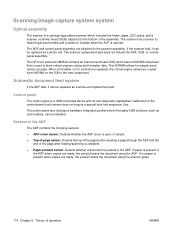
... present in the ADF The ADF contains the following sensors: ● ADF-cover sensor. Sensors in the ADF. The HP Color LaserJet CM3530 contains an interconnect board (ICB) which includes the frame, glass, LED optics, and a scanner controller board (SCB) attached to the bottom of the assembly. This NVRAM allows for simpler save/ restore process. Calibration of the...
... present in the ADF The ADF contains the following sensors: ● ADF-cover sensor. Sensors in the ADF. The HP Color LaserJet CM3530 contains an interconnect board (ICB) which includes the frame, glass, LED optics, and a scanner controller board (SCB) attached to the bottom of the assembly. This NVRAM allows for simpler save/ restore process. Calibration of the...
Service Manual
Page 213
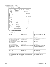
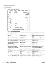
...: fuser sensors J127: pre-exposure LEDs (rear), SR17, SL1 J105: interconnect board (ICB) J116: HVPS upper J130: registration density (RD) sensors (front and rear) J106: 500-sheet feeder, developing home position, laser motors J117: fuser motor J131: pickup motor J107: duplex sensor, tray 1 ... to HVPS lower J111: CK laser J122: OHT out J139: fuser sensors J112: pre-exposure LEDs (front) J123: pressure release, bin full, fuser delivery J140: lift motor, tray present, stack surface J113: 24 v to high-voltage power supply J124: 24 v to scanner-control board (HVPS) upper (SCB) J143:...
...: fuser sensors J127: pre-exposure LEDs (rear), SR17, SL1 J105: interconnect board (ICB) J116: HVPS upper J130: registration density (RD) sensors (front and rear) J106: 500-sheet feeder, developing home position, laser motors J117: fuser motor J131: pickup motor J107: duplex sensor, tray 1 ... to HVPS lower J111: CK laser J122: OHT out J139: fuser sensors J112: pre-exposure LEDs (front) J123: pressure release, bin full, fuser delivery J140: lift motor, tray present, stack surface J113: 24 v to high-voltage power supply J124: 24 v to scanner-control board (HVPS) upper (SCB) J143:...
Service Manual
Page 309
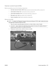
... assembly on page 242. CAUTION: Dust or debris can scratch the scanner glass and cause print-quality problems. If possible, place the scanner on page 218. ● Control-panel assembly. See Control-panel overlay on a clean lint-free cloth. 2. Scanner-control board (SCB) Before proceeding, remove the following components: ● Automatic document feeder (ADF). See Automatic document...
... assembly on page 242. CAUTION: Dust or debris can scratch the scanner glass and cause print-quality problems. If possible, place the scanner on page 218. ● Control-panel assembly. See Control-panel overlay on a clean lint-free cloth. 2. Scanner-control board (SCB) Before proceeding, remove the following components: ● Automatic document feeder (ADF). See Automatic document...
Service Manual
Page 386
...Main-drive assembly on page 339. ● Main-drive assembly. Formatter PCA on page 270. ● Low-voltage power supply (LVPS). See DC controller PCA and tray on page 192. ● Fuser. See Secondary transfer assembly on page 300. ● High-voltage power supply lower. See Power-...207. ● Front-upper cover. See Front-upper cover on page 238. ● Scanner assembly. See Rear cover on page 225 ● Right-rear cover. See Interconnect board (ICB) on page 262 ● Interconnect board (ICB). See Rear-top cover on page 267. See High-voltage power supply lower on...
...Main-drive assembly on page 339. ● Main-drive assembly. Formatter PCA on page 270. ● Low-voltage power supply (LVPS). See DC controller PCA and tray on page 192. ● Fuser. See Secondary transfer assembly on page 300. ● High-voltage power supply lower. See Power-...207. ● Front-upper cover. See Front-upper cover on page 238. ● Scanner assembly. See Rear cover on page 225 ● Right-rear cover. See Interconnect board (ICB) on page 262 ● Interconnect board (ICB). See Rear-top cover on page 267. See High-voltage power supply lower on...
Service Manual
Page 391
... Rear cover on page 267. ● DC controller PCA. See Interconnect board (ICB) on page 238. ● Scanner assembly. See Main-drive assembly on page 233. ● Rear-upper cover. See Left cover on page 346. ● Fuser-drive assembly. See Scanner assembly on page 300. ● High-voltage power... supply lower. See Power-supply fan and fan duct on page 242. ● Front-top cover. See Fuser-drive assembly on page 262 ● Interconnect board (ICB). See Rear-top cover on page...
... Rear cover on page 267. ● DC controller PCA. See Interconnect board (ICB) on page 238. ● Scanner assembly. See Main-drive assembly on page 233. ● Rear-upper cover. See Left cover on page 346. ● Fuser-drive assembly. See Scanner assembly on page 300. ● High-voltage power... supply lower. See Power-supply fan and fan duct on page 242. ● Front-top cover. See Fuser-drive assembly on page 262 ● Interconnect board (ICB). See Rear-top cover on page...
Service Manual
Page 396
.... ● Power-supply fan and fan duct. See Left cover on page 267. ● DC controller PCA. See Interconnect board (ICB) on page 233. ● Rear-upper cover. See High-voltage power supply upper on page 238. ● Scanner assembly. Duplex-drive assembly Before proceeding, remove the following components: ● Fuser. See Rear...
.... ● Power-supply fan and fan duct. See Left cover on page 267. ● DC controller PCA. See Interconnect board (ICB) on page 233. ● Rear-upper cover. See High-voltage power supply upper on page 238. ● Scanner assembly. Duplex-drive assembly Before proceeding, remove the following components: ● Fuser. See Rear...
Service Manual
Page 442
...: fuser sensors J127: pre-exposure LEDs (rear), SR17, SL1 J105: interconnect board (ICB) J116: HVPS upper J130: registration density (RD) sensors (front and rear) J106: 500-sheet feeder, developing home position, laser motors J117: fuser motor J131: pickup motor J107: duplex sensor, tray 1 ... to HVPS lower J111: CK laser J122: OHT out J139: fuser sensors J112: pre-exposure LEDs (front) J123: pressure release, bin full, fuser delivery J140: lift motor, tray present, stack surface J113: 24 v to high-voltage power supply J124: 24 v to scanner-control board (HVPS) upper (SCB) J143:...
...: fuser sensors J127: pre-exposure LEDs (rear), SR17, SL1 J105: interconnect board (ICB) J116: HVPS upper J130: registration density (RD) sensors (front and rear) J106: 500-sheet feeder, developing home position, laser motors J117: fuser motor J131: pickup motor J107: duplex sensor, tray 1 ... to HVPS lower J111: CK laser J122: OHT out J139: fuser sensors J112: pre-exposure LEDs (front) J123: pressure release, bin full, fuser delivery J140: lift motor, tray present, stack surface J113: 24 v to high-voltage power supply J124: 24 v to scanner-control board (HVPS) upper (SCB) J143:...
Service Manual
Page 449
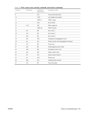
...motors, fans, switches, solenoids, and clutches (continued) Location Connector Component abbreviation Component name 9 ICB Interconnect board (ICB) 10 LVPS Low-voltage power supply 11 HVPS (t) HVPS-T upper 12 DCC DC Controller 13 J119 FM1 Power-supply fan 14 HVPS (d) HVPS-D (lower) 15 J41 M3 Drum motor 1...19 J8 SL1 Primary transfer roller disengagement solenoid 20 J15 M2 Fuser motor 21 J55 M9 Yellow/magenta scanner motor 22 J56 M8 Cyan/black scanner motor 23 J20 M11 Duplex reverse motor 24 J21 SL2 Duplex reverse solenoid 25 J6 M13 Pickup ...
...motors, fans, switches, solenoids, and clutches (continued) Location Connector Component abbreviation Component name 9 ICB Interconnect board (ICB) 10 LVPS Low-voltage power supply 11 HVPS (t) HVPS-T upper 12 DCC DC Controller 13 J119 FM1 Power-supply fan 14 HVPS (d) HVPS-D (lower) 15 J41 M3 Drum motor 1...19 J8 SL1 Primary transfer roller disengagement solenoid 20 J15 M2 Fuser motor 21 J55 M9 Yellow/magenta scanner motor 22 J56 M8 Cyan/black scanner motor 23 J20 M11 Duplex reverse motor 24 J21 SL2 Duplex reverse solenoid 25 J6 M13 Pickup ...
Service Manual
Page 473
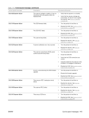
... scanner-control board (SCB) cannot communicate with the product. 1. Replace the SCB. See Scanner assembly on page 242. 30.01.40 Scanner failure The scanner AFE 2 failed. 1. Replace the scanner. See Scanner assembly on page 279. 30.01.39 Scanner failure There was a SCB error. 1. See Scanner-control board (SCB) on page 279. 30.01.18 Scanner failure The SCB ASIC failed. 1. See Scanner-control board...
... scanner-control board (SCB) cannot communicate with the product. 1. Replace the SCB. See Scanner assembly on page 242. 30.01.40 Scanner failure The scanner AFE 2 failed. 1. Replace the scanner. See Scanner assembly on page 279. 30.01.39 Scanner failure There was a SCB error. 1. See Scanner-control board (SCB) on page 279. 30.01.18 Scanner failure The SCB ASIC failed. 1. See Scanner-control board...
Service Manual
Page 474
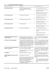
...Load Tray : [Type] [Size] The specified tray is loaded with the size and type indicated. Replace the SCB. Check the SCB connections. 4. See Scanner-control board (SCB) on . 2. The Touch OK to the error condition: 1. Turn the product off and then on A firmware error has occurred. This problem ... use it has been acclimated. If the error is another tray is not adjusted correctly. Replace the SCB. See Scanner-control board (SCB) on page 279. 30.01.44 Scanner failure Communication failed on . 2. The tray is a cassette and there is not cleared, turn the product off ...
...Load Tray : [Type] [Size] The specified tray is loaded with the size and type indicated. Replace the SCB. Check the SCB connections. 4. See Scanner-control board (SCB) on . 2. The Touch OK to the error condition: 1. Turn the product off and then on A firmware error has occurred. This problem ... use it has been acclimated. If the error is another tray is not adjusted correctly. Replace the SCB. See Scanner-control board (SCB) on page 279. 30.01.44 Scanner failure Communication failed on . 2. The tray is a cassette and there is not cleared, turn the product off ...
Service Manual
Page 529
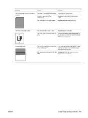
...The roller or media feed guide is damaged. Replace the print cartridge. If the dirt does not come off, replace the fuser. The scanner-control board (SCB) has Replace the SCB. Replace any dirty components. See Fuser on page 279. The paper feed guide is dirty. The ... paper-feed-guide unit. Execute a Pressure roller clean mode. ENWW Solve image-quality problems 499 sure that no media is dirty. See Scanner-control failed. The front of the page is deformed or has deteriorated. Problem The printed page contains wrinkles or creases. A roller is dirty....
...The roller or media feed guide is damaged. Replace the print cartridge. If the dirt does not come off, replace the fuser. The scanner-control board (SCB) has Replace the SCB. Replace any dirty components. See Fuser on page 279. The paper feed guide is dirty. The ... paper-feed-guide unit. Execute a Pressure roller clean mode. ENWW Solve image-quality problems 499 sure that no media is dirty. See Scanner-control failed. The front of the page is deformed or has deteriorated. Problem The printed page contains wrinkles or creases. A roller is dirty....
Service Manual
Page 534
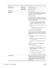
...calendar year. NOTE: A six-day grace period is 17, so that the product was first used on the control panel. ENWW YY = 12. 2. If there is the date. Since there is 2002. 2. 287 divided... following formula to get the actual year that is the tenth month of warranty. If you replace a formatter board in a country/region that is stored in step 2 is built into the installation date as follows: 1....reset, the paper size that uses A4 as follows: 2002 - 1990 = 12. Menu item Scanner Settings Serial number SERVICE ID Cold Reset Paper 504 Chapter 7 Solve problems Sub-menu item ADF ...
...calendar year. NOTE: A six-day grace period is 17, so that the product was first used on the control panel. ENWW YY = 12. 2. If there is the date. Since there is 2002. 2. 287 divided... following formula to get the actual year that is the tenth month of warranty. If you replace a formatter board in a country/region that is stored in step 2 is built into the installation date as follows: 1....reset, the paper size that uses A4 as follows: 2002 - 1990 = 12. Menu item Scanner Settings Serial number SERVICE ID Cold Reset Paper 504 Chapter 7 Solve problems Sub-menu item ADF ...
Service Manual
Page 588
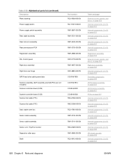
... page 523 Right door assembly on page 525 Internal components (4 of 5) on page 533 Formatter components on page 549 ADF/scanner assembly on page 521 ADF/scanner assembly on page 521 PCAs on page 547 Internal components (4 of 5) on page 533 Internal components (4 of 5) on ...Rear pre-exposure PCA Registration assembly Rib, Control panel Right door assembly Right door rear hinge SATA hard drive cable power/data Scanner assembly (ADF assembly and SCB PCA are not included) Scanner controller board (SCB) Scanner controller board (SCB) Scanner flat cable (FFC) Scanner flat cable (FFC) Seal, waste toner...
... page 523 Right door assembly on page 525 Internal components (4 of 5) on page 533 Formatter components on page 549 ADF/scanner assembly on page 521 ADF/scanner assembly on page 521 PCAs on page 547 Internal components (4 of 5) on page 533 Internal components (4 of 5) on ...Rear pre-exposure PCA Registration assembly Rib, Control panel Right door assembly Right door rear hinge SATA hard drive cable power/data Scanner assembly (ADF assembly and SCB PCA are not included) Scanner controller board (SCB) Scanner controller board (SCB) Scanner flat cable (FFC) Scanner flat cable (FFC) Seal, waste toner...
Service Manual
Page 591
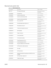
... Numerical parts list Part number Description 5851-3141 PCI express RoHS cable CC452-60001 CC453-60001 CC454-60002 Formatter PCA Interconnect board (ICB) Scanner controller board (SCB) CC454-60002 CC456-60001 Scanner controller board (SCB) Fax controller PCA CC468-67906 500-sheet paper feeder right door kit CC468-67907 ITB assembly service kit CC468-67914 Transfer roller assembly...
... Numerical parts list Part number Description 5851-3141 PCI express RoHS cable CC452-60001 CC453-60001 CC454-60002 Formatter PCA Interconnect board (ICB) Scanner controller board (SCB) CC454-60002 CC456-60001 Scanner controller board (SCB) Fax controller PCA CC468-67906 500-sheet paper feeder right door kit CC468-67907 ITB assembly service kit CC468-67914 Transfer roller assembly...


