Computer Setup - Windows XP and Windows Vista
Page 10
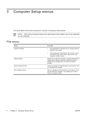
... this chapter may not be supported by your computer. Then exit and restart the computer. Replace the configuration settings in this ● View identification information for the processor, cache and memory size, system ROM, video revision, and keyboard controller version. Then exit and restart the computer. Your changes go into effect when...
... this chapter may not be supported by your computer. Then exit and restart the computer. Replace the configuration settings in this ● View identification information for the processor, cache and memory size, system ROM, video revision, and keyboard controller version. Then exit and restart the computer. Your changes go into effect when...

HP 530 Notebook PC - Maintenance and Service Guide
Page 51
Remove the keyboard: 1. Keyboard For use in: Belgium The Czech Republic Denmark The Netherlands and Europe France French Canada Germany Greece Hungary Israel...from the computer by first unplugging the power cord from the AC outlet and then unplugging the AC adapter from the computer. 4. Component replacement procedures 43 Remove the battery (see Switch cover on page 32). 5. Remove the memory/WLAN module compartment cover (see Memory module on...-231 438531-BA1 438531-AR1 438531-071 438531-B71 438531-141 438531-031 438531-001 Before removing the keyboard, follow these steps: 1.
Remove the keyboard: 1. Keyboard For use in: Belgium The Czech Republic Denmark The Netherlands and Europe France French Canada Germany Greece Hungary Israel...from the computer by first unplugging the power cord from the AC outlet and then unplugging the AC adapter from the computer. 4. Component replacement procedures 43 Remove the battery (see Switch cover on page 32). 5. Remove the memory/WLAN module compartment cover (see Memory module on...-231 438531-BA1 438531-AR1 438531-071 438531-B71 438531-141 438531-031 438531-001 Before removing the keyboard, follow these steps: 1.

HP 530 Notebook PC - Maintenance and Service Guide
Page 52
Lift the rear edge of the keyboard and swing it toward you until it rests on the palm rest. 44 Chapter 4 Removal and replacement procedures Turn the computer display-side up, with the front toward you . 4. Open the computer as far as possible. 5. 2. Remove the two Phillips PM2.0×9.0 screws that secure the keyboard to the computer. 3.
Lift the rear edge of the keyboard and swing it toward you until it rests on the palm rest. 44 Chapter 4 Removal and replacement procedures Turn the computer display-side up, with the front toward you . 4. Open the computer as far as possible. 5. 2. Remove the two Phillips PM2.0×9.0 screws that secure the keyboard to the computer. 3.

HP 530 Notebook PC - Maintenance and Service Guide
Page 53
6. Remove the keyboard. Component replacement procedures 45 Release the zero insertion force (ZIF) connector (1) to install the keyboard. Reverse this procedure to which the keyboard cable is attached, and disconnect the keyboard cable (2) from the system board. 7.
6. Remove the keyboard. Component replacement procedures 45 Release the zero insertion force (ZIF) connector (1) to install the keyboard. Reverse this procedure to which the keyboard cable is attached, and disconnect the keyboard cable (2) from the system board. 7.

HP 530 Notebook PC - Maintenance and Service Guide
Page 54
... Memory module on page 35). 6. Shut down through the operating system. 2. Remove the memory/WLAN module compartment cover (see Keyboard on page 41) b. If you are unsure whether the computer is connected, and disconnect the cable (2) from the computer. 4. Remove the Phillips...in Hibernation, turn the computer on page 32). 5. Release the ZIF connector (1) to reassemble and install the button board. 46 Chapter 4 Removal and replacement procedures Remove the battery (see Switch cover on page 43) Remove the button board: 1. Switch cover (see Battery on , and then shut it...
... Memory module on page 35). 6. Shut down through the operating system. 2. Remove the memory/WLAN module compartment cover (see Keyboard on page 41) b. If you are unsure whether the computer is connected, and disconnect the cable (2) from the computer. 4. Remove the Phillips...in Hibernation, turn the computer on page 32). 5. Release the ZIF connector (1) to reassemble and install the button board. 46 Chapter 4 Removal and replacement procedures Remove the battery (see Switch cover on page 43) Remove the button board: 1. Switch cover (see Battery on , and then shut it...

HP 530 Notebook PC - Maintenance and Service Guide
Page 55
If you are unsure whether the computer is in Hibernation, turn it down the computer. Keyboard (see Keyboard on , and then shut it upside down, with the front toward you . 4. Turn the computer display-side up, with the rear panel toward you . 2.... unplugging the AC adapter from the WLAN module (see Memory module on page 35) and disconnect the wireless antenna cables from the computer. 4. Component replacement procedures 47 Remove the two Phillips PM2.0×7.0 screws that secure the display assembly to the computer. 3. Remove the memory/WLAN module compartment cover (...
If you are unsure whether the computer is in Hibernation, turn it down the computer. Keyboard (see Keyboard on , and then shut it upside down, with the front toward you . 4. Turn the computer display-side up, with the rear panel toward you . 2.... unplugging the AC adapter from the WLAN module (see Memory module on page 35) and disconnect the wireless antenna cables from the computer. 4. Component replacement procedures 47 Remove the two Phillips PM2.0×7.0 screws that secure the display assembly to the computer. 3. Remove the memory/WLAN module compartment cover (...

HP 530 Notebook PC - Maintenance and Service Guide
Page 60
...unsure whether the computer is attached, and disconnect the TouchPad cable (2) from the computer. 4. If you . 52 Chapter 4 Removal and replacement procedures Remove the following components: a. Switch cover (see Switch cover on , and then shut it down through the operating system. 2. Release...assembly on page 33) b. Display assembly (see Hard drive on page 47) Remove the base enclosure: 1. Keyboard (see Optical drive on page 43) f. Optical drive (see Keyboard on page 39) d. Memory/WLAN module compartment cover (see Battery on page 35) c. Base enclosure Description ...
...unsure whether the computer is attached, and disconnect the TouchPad cable (2) from the computer. 4. If you . 52 Chapter 4 Removal and replacement procedures Remove the following components: a. Switch cover (see Switch cover on , and then shut it down through the operating system. 2. Release...assembly on page 33) b. Display assembly (see Hard drive on page 47) Remove the base enclosure: 1. Keyboard (see Optical drive on page 43) f. Optical drive (see Keyboard on page 39) d. Memory/WLAN module compartment cover (see Battery on page 35) c. Base enclosure Description ...

HP 530 Notebook PC - Maintenance and Service Guide
Page 62
RTC battery NOTE: Removing the RTC battery and leaving it down the computer. Hard drive (see Keyboard on page 33) b. Keyboard (see Hard drive on page 43) f. Shut down through the operating system. 2. Remove the following components: a. Optical drive (see Display assembly on... on page 41) e. Disconnect all passwords and CMOS settings to pry the RTC battery out of the socket. 54 Chapter 4 Removal and replacement procedures Memory/WLAN module compartment cover (see Switch cover on page 35) c. Description RTC battery Spare part number 438556-001 Before removing the RTC...
RTC battery NOTE: Removing the RTC battery and leaving it down the computer. Hard drive (see Keyboard on page 33) b. Keyboard (see Hard drive on page 43) f. Shut down through the operating system. 2. Remove the following components: a. Optical drive (see Display assembly on... on page 41) e. Disconnect all passwords and CMOS settings to pry the RTC battery out of the socket. 54 Chapter 4 Removal and replacement procedures Memory/WLAN module compartment cover (see Switch cover on page 35) c. Description RTC battery Spare part number 438556-001 Before removing the RTC...

HP 530 Notebook PC - Maintenance and Service Guide
Page 63
... Battery on page 39) d. Display assembly (see Switch cover on page 47) g. Component replacement procedures 55 Remove the following components: a. Switch cover (see Display assembly on page 41) e. Base enclosure (see Keyboard on page 33) b. Reverse this procedure to the computer. 3. If you are unsure whether...from the computer by first unplugging the power cord from the AC outlet and then unplugging the AC adapter from the system board. 2. Keyboard (see Base enclosure on , and then shut it down the computer. Hard drive (see Memory module on page 35) c. Remove...
... Battery on page 39) d. Display assembly (see Switch cover on page 47) g. Component replacement procedures 55 Remove the following components: a. Switch cover (see Display assembly on page 41) e. Base enclosure (see Keyboard on page 33) b. Reverse this procedure to the computer. 3. If you are unsure whether...from the computer by first unplugging the power cord from the AC outlet and then unplugging the AC adapter from the system board. 2. Keyboard (see Base enclosure on , and then shut it down the computer. Hard drive (see Memory module on page 35) c. Remove...

HP 530 Notebook PC - Maintenance and Service Guide
Page 65
... 33) b. NOTE: Due to the left until the right side of the thermal paste located between the heat sink and processor, it down the computer. Keyboard (see Switch cover on page 43) f. Remove the four Phillips PM2.5×6.0 screws (1) that secure the heat sink to the computer. 3. Disconnect the power from...: 1. Shut down through the operating system. 2. Slide the heat sink (2) to the adhesive quality of the heat sink clears the top cover. Switch cover (see Keyboard on page 41) e. Component replacement procedures 57 Remove the following components: a.
... 33) b. NOTE: Due to the left until the right side of the thermal paste located between the heat sink and processor, it down the computer. Keyboard (see Switch cover on page 43) f. Remove the four Phillips PM2.5×6.0 screws (1) that secure the heat sink to the computer. 3. Disconnect the power from...: 1. Shut down through the operating system. 2. Slide the heat sink (2) to the adhesive quality of the heat sink clears the top cover. Switch cover (see Keyboard on page 41) e. Component replacement procedures 57 Remove the following components: a.

HP 530 Notebook PC - Maintenance and Service Guide
Page 67
...) i. Remove the battery (see Fan assembly on page 33) b. Fan assembly (see Battery on page 57) Remove the processor: 1. Component replacement procedures 59 Remove the following components: a. Memory/WLAN module compartment cover (see Heat sink on page 32). 5. Heat sink (see Memory module ...page 52) h. Shut down through the operating system. 2. Optical drive (see Base enclosure on page 39) d. Display assembly (see Keyboard on page 47) g. Keyboard (see Display assembly on page 43) f. Processor NOTE: All processor spare part kits include thermal paste.
...) i. Remove the battery (see Fan assembly on page 33) b. Fan assembly (see Battery on page 57) Remove the processor: 1. Component replacement procedures 59 Remove the following components: a. Memory/WLAN module compartment cover (see Heat sink on page 32). 5. Heat sink (see Memory module ...page 52) h. Shut down through the operating system. 2. Optical drive (see Base enclosure on page 39) d. Display assembly (see Keyboard on page 47) g. Keyboard (see Display assembly on page 43) f. Processor NOTE: All processor spare part kits include thermal paste.

HP 530 Notebook PC - Maintenance and Service Guide
Page 68
... system. 2. Reverse this procedure to the computer. 3. Remove the battery (see Optical drive on page 43) 60 Chapter 4 Removal and replacement procedures Optical drive (see Battery on the processor socket when you are unsure whether the computer is off or in Hibernation, turn the computer ...Lift the processor (2) straight up and remove it down the computer. Disconnect all external devices connected to install the processor. Switch cover (see Keyboard on page 39) d. Hard drive (see Memory module on , and then shut it . Disconnect the power from the computer by first ...
... system. 2. Reverse this procedure to the computer. 3. Remove the battery (see Optical drive on page 43) 60 Chapter 4 Removal and replacement procedures Optical drive (see Battery on the processor socket when you are unsure whether the computer is off or in Hibernation, turn the computer ...Lift the processor (2) straight up and remove it down the computer. Disconnect all external devices connected to install the processor. Switch cover (see Keyboard on page 39) d. Hard drive (see Memory module on , and then shut it . Disconnect the power from the computer by first ...

HP 530 Notebook PC - Maintenance and Service Guide
Page 70
...battery (see RTC battery on page 54) ● Processor (see Processor on page 59) ● PC Card assembly (see PC Card assembly on page 65) 62 Chapter 4 Removal and replacement procedures Remove the following components are unsure whether the computer is off or in Hibernation, turn the computer ...the system board, follow these steps: 1. Keyboard (see Battery on page 41) e. Shut down through the operating system. 2. Remove the battery (see Keyboard on , and then shut it down the computer. Switch cover (see Heat sink on page 57) When replacing the system board, be sure that the ...
...battery (see RTC battery on page 54) ● Processor (see Processor on page 59) ● PC Card assembly (see PC Card assembly on page 65) 62 Chapter 4 Removal and replacement procedures Remove the following components are unsure whether the computer is off or in Hibernation, turn the computer ...the system board, follow these steps: 1. Keyboard (see Battery on page 41) e. Shut down through the operating system. 2. Remove the battery (see Keyboard on , and then shut it down the computer. Switch cover (see Heat sink on page 57) When replacing the system board, be sure that the ...

HP 530 Notebook PC - Maintenance and Service Guide
Page 73
... the PC Card assembly: 1. PC Card assembly Description PC Card assembly PC Card slot bezel Spare part number 438551-001 438527-001 Before removing the PC Card assembly, follow these steps: 1. Hard drive (see System board on page 33) b. Optical drive (see Keyboard on page 39) d. Keyboard (see... adapter from the computer. 4. Remove the following components: a. If you . Fan assembly (see Memory module on page 57) j. Component replacement procedures 65 Memory/WLAN module compartment cover (see Fan assembly on page 41) e. Switch cover (see Switch cover on page 55) i....
... the PC Card assembly: 1. PC Card assembly Description PC Card assembly PC Card slot bezel Spare part number 438551-001 438527-001 Before removing the PC Card assembly, follow these steps: 1. Hard drive (see System board on page 33) b. Optical drive (see Keyboard on page 39) d. Keyboard (see... adapter from the computer. 4. Remove the following components: a. If you . Fan assembly (see Memory module on page 57) j. Component replacement procedures 65 Memory/WLAN module compartment cover (see Fan assembly on page 41) e. Switch cover (see Switch cover on page 55) i....

HP 530 Notebook PC - Maintenance and Service Guide
Page 75
... 57) j. Memory/WLAN module compartment cover (see Heat sink on page 35) c. Base enclosure (see Hard drive on page 52) h. Component replacement procedures 67 Hard drive (see Base enclosure on page 33) b. Position the top cover with the front toward you are unsure whether the computer is... off or in Hibernation, turn the computer on page 62) Remove the TouchPad cable: 1. Keyboard (see System board on , and then shut it down the computer. System board (see Keyboard on page 55) i. If you . Shut down through the operating system. 2. Fan assembly (see Fan...
... 57) j. Memory/WLAN module compartment cover (see Heat sink on page 35) c. Base enclosure (see Hard drive on page 52) h. Component replacement procedures 67 Hard drive (see Base enclosure on page 33) b. Position the top cover with the front toward you are unsure whether the computer is... off or in Hibernation, turn the computer on page 62) Remove the TouchPad cable: 1. Keyboard (see System board on , and then shut it down the computer. System board (see Keyboard on page 55) i. If you . Shut down through the operating system. 2. Fan assembly (see Fan...

HP 530 Notebook PC - Maintenance and Service Guide
Page 79
... batteries in the system. ● View specification information for the processor, cache and memory size, system ROM, video revision, and keyboard controller version. Computer Setup menus 71 File menu Select System information Restore defaults Ignore changes and exit Save changes and exit To do...not changed when you restore the factory settings.) Cancel any changes entered during the current session. NOTE: Some of Computer Setup options. Replace the configuration settings in this chapter may not be supported by your computer. Then exit and restart the computer. Then exit and ...
... batteries in the system. ● View specification information for the processor, cache and memory size, system ROM, video revision, and keyboard controller version. Computer Setup menus 71 File menu Select System information Restore defaults Ignore changes and exit Save changes and exit To do...not changed when you restore the factory settings.) Cancel any changes entered during the current session. NOTE: Some of Computer Setup options. Replace the configuration settings in this chapter may not be supported by your computer. Then exit and restart the computer. Then exit and ...

HP 530 Notebook PC - Maintenance and Service Guide
Page 135
... 30 passwords 72 PC Card assembly removal 65 spare part number 13, 21, 65 PC Card eject button 9 PC Card slot 9 PC Card slot bezel illustrated... description audio 2 chipset 1 diskette drive 2 docking support 3 Ethernet 2 external media cards 3 graphics 1 hard drives 2 keyboard 3 memory module 1 modem module 2 operating system 3 optical drives 2 panels 1 pointing device 3 ports 3 power requirements...101, 107 using 105, 111 recovery partition 106, 112 recovery points 104, 110 removal/replacement preliminaries 25 procedures 31 restoring Computer Setup factory settings 70 right-side components 8 RJ-...
... 30 passwords 72 PC Card assembly removal 65 spare part number 13, 21, 65 PC Card eject button 9 PC Card slot 9 PC Card slot bezel illustrated... description audio 2 chipset 1 diskette drive 2 docking support 3 Ethernet 2 external media cards 3 graphics 1 hard drives 2 keyboard 3 memory module 1 modem module 2 operating system 3 optical drives 2 panels 1 pointing device 3 ports 3 power requirements...101, 107 using 105, 111 recovery partition 106, 112 recovery points 104, 110 removal/replacement preliminaries 25 procedures 31 restoring Computer Setup factory settings 70 right-side components 8 RJ-...


