
Service Manual
Page 7
...Assembly 6-21 Left and Right Side Covers 6-23 Tray 1 Inner Cover 6-24 Right and Left Corner Covers 6-26 Removing Assemblies 6-27 Transfer Roller Assembly 6-28 Fuser 6-30 Paper Handling PCA 6-31 Main Gear Assembly 6-35 Pickup Gear Assembly 6-37 Tray 1 Pickup Solenoid 6-39 Fan 6-40 Formatter Assembly 6-41 Tray 1 ... Sensor 6-60 Face Down Bin Full Sensor 6-61 Power Connection 6-63 Registration Assembly 6-64 Upper Delivery Assembly 6-66 Delivery Roller Removal 6-68 Laser Scanner Assembly 6-70 Main Motor 6-71 Toner Cartridge Guides 6-72 Power Inlet Assembly 6-73 4 Contents EN
...Assembly 6-21 Left and Right Side Covers 6-23 Tray 1 Inner Cover 6-24 Right and Left Corner Covers 6-26 Removing Assemblies 6-27 Transfer Roller Assembly 6-28 Fuser 6-30 Paper Handling PCA 6-31 Main Gear Assembly 6-35 Pickup Gear Assembly 6-37 Tray 1 Pickup Solenoid 6-39 Fan 6-40 Formatter Assembly 6-41 Tray 1 ... Sensor 6-60 Face Down Bin Full Sensor 6-61 Power Connection 6-63 Registration Assembly 6-64 Upper Delivery Assembly 6-66 Delivery Roller Removal 6-68 Laser Scanner Assembly 6-70 Main Motor 6-71 Toner Cartridge Guides 6-72 Power Inlet Assembly 6-73 4 Contents EN

Service Manual
Page 24
...; Use long-grain paper. Some paper causes print quality problems, jamming, or damage to printer. faulty paper lot. Store paper flat in its moistureproof wrapping. Jamming, damage to the printer. Do not use conventional 20 lb (75 g/m2) paper. EN Paper Specifications 1-15 ...Guidelines for Using Paper Symptom Problem with feeding. Problems with cutouts or perforations. Increased gray background shading. Set FUSER MODE=LOW. Cutouts or perforations....
...; Use long-grain paper. Some paper causes print quality problems, jamming, or damage to printer. faulty paper lot. Store paper flat in its moistureproof wrapping. Jamming, damage to the printer. Do not use conventional 20 lb (75 g/m2) paper. EN Paper Specifications 1-15 ...Guidelines for Using Paper Symptom Problem with feeding. Problems with cutouts or perforations. Increased gray background shading. Set FUSER MODE=LOW. Cutouts or perforations....

Service Manual
Page 54
... select YES, scroll back to NORMAL by default. Note To see the default fuser mode for each paper type. (This is only necessary if you are experiencing problems printing on certain paper types.) NO: The fuser mode menu items are set to the Information Menu, and print a menu map ...(page 3-6). [TYPE]= NORMAL NORMAL LOW HIGH VELLUM This item appears only when CONFIGURE FUSER MODE MENU=YES. ROUGH=HIGH VELLUM=VELLUM For a complete list of supported paper types, see below). EN Control Panel Menus 3-9 YES: Additional items appear...
... select YES, scroll back to NORMAL by default. Note To see the default fuser mode for each paper type. (This is only necessary if you are experiencing problems printing on certain paper types.) NO: The fuser mode menu items are set to the Information Menu, and print a menu map ...(page 3-6). [TYPE]= NORMAL NORMAL LOW HIGH VELLUM This item appears only when CONFIGURE FUSER MODE MENU=YES. ROUGH=HIGH VELLUM=VELLUM For a complete list of supported paper types, see below). EN Control Panel Menus 3-9 YES: Additional items appear...

Service Manual
Page 88
... Paper Pickup, Feed, and Use a water-dampened, lint-free cloth. Transfer Roller Use a dry, lint-free cloth. Fuser Use a water-dampened, lint-free cloth. Cleaning the Printer Component Cleaning Method / Notes Outside Covers Use a water-dampened cloth. Separation Rollers Separation Pad Use a dry, lint-free cloth.... EN Cleaning the Printer and Accessories 4-3 Inside General With a dry lint-free cloth, wipe any dust, spilled toner, and paper particles from the paper path...
... Paper Pickup, Feed, and Use a water-dampened, lint-free cloth. Transfer Roller Use a dry, lint-free cloth. Fuser Use a water-dampened, lint-free cloth. Cleaning the Printer Component Cleaning Method / Notes Outside Covers Use a water-dampened cloth. Separation Rollers Separation Pad Use a dry, lint-free cloth.... EN Cleaning the Printer and Accessories 4-3 Inside General With a dry lint-free cloth, wipe any dust, spilled toner, and paper particles from the paper path...
Service Manual
Page 90
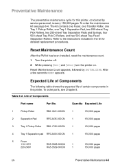
...Rollers. Reset Maintenance Count After the PM kit has been installed, reset the maintenance count. 1 Turn the printer off. 2 While pressing [Item-] and [Value-] turn the printer on. Expected Life of Components The following table shows the expected life of Components Part name Part No.... this printer, conducted by INITIALIZING. Quantity Expected Life 1 Pickup Roller RB2-1821-000CN 1 150,000 pages 2 Separation Pad RF5-2435-000CN 1 150,000 pages 3 Tray 1 Pickup Roller RB2-1795-000CN 1 150,000 pages 4 Tray 1 Separation pad RF5-2400-000CN 1 150,000 pages 5 Fuser 110...
...Rollers. Reset Maintenance Count After the PM kit has been installed, reset the maintenance count. 1 Turn the printer off. 2 While pressing [Item-] and [Value-] turn the printer on. Expected Life of Components The following table shows the expected life of Components Part name Part No.... this printer, conducted by INITIALIZING. Quantity Expected Life 1 Pickup Roller RB2-1821-000CN 1 150,000 pages 2 Separation Pad RF5-2435-000CN 1 150,000 pages 3 Tray 1 Pickup Roller RB2-1795-000CN 1 150,000 pages 4 Tray 1 Separation pad RF5-2400-000CN 1 150,000 pages 5 Fuser 110...

Service Manual
Page 103
The Formatter PCA receives a print job from the Configuration Menu) conserves power by shutting down the Fuser and exhaust fans after the printer has been idle for an adjustable period of time. Formatter System The Formatter PCA is POWERSAVE ON, with the Paper ...Output Systems, and then signals the Formatter to send the print image data. q Storing font information. q Monitoring Control Panel inputs and relaying printer status information (through the Bidirectional Interface. The DC Controller Board synchronizes the Image Formation System with a 30-minute idle time. 5-12 Functional ...
The Formatter PCA receives a print job from the Configuration Menu) conserves power by shutting down the Fuser and exhaust fans after the printer has been idle for an adjustable period of time. Formatter System The Formatter PCA is POWERSAVE ON, with the Paper ...Output Systems, and then signals the Formatter to send the print image data. q Storing font information. q Monitoring Control Panel inputs and relaying printer status information (through the Bidirectional Interface. The DC Controller Board synchronizes the Image Formation System with a 30-minute idle time. 5-12 Functional ...

Service Manual
Page 110
Figure 5-6 Image Formation System After the image has been transferred to the paper, it is then fused onto the paper by heat and pressure at the Fuser. EN Image Formation System 5-19
Figure 5-6 Image Formation System After the image has been transferred to the paper, it is then fused onto the paper by heat and pressure at the Fuser. EN Image Formation System 5-19

Service Manual
Page 118
If the fusing system overheats (about 446° F/230° C), a relay opens, interrupting power to the Fuser. The DC Controller Board maintains a variable fuser temperature that provides heat for the fusing process. The paper passes between a heated fusing roller and a soft pressure roller. ... fusing system exceeds 464° F (240° C), the thermal fuse will open, cutting off power to the Fusing Heater, causing a Fuser error message (50.X FUSER ERROR). The fusing roller contains a ceramic heating element that is monitored by heat and pressure to produce a permanent image.
If the fusing system overheats (about 446° F/230° C), a relay opens, interrupting power to the Fuser. The DC Controller Board maintains a variable fuser temperature that provides heat for the fusing process. The paper passes between a heated fusing roller and a soft pressure roller. ... fusing system exceeds 464° F (240° C), the thermal fuse will open, cutting off power to the Fusing Heater, causing a Fuser error message (50.X FUSER ERROR). The fusing roller contains a ceramic heating element that is monitored by heat and pressure to produce a permanent image.

Service Manual
Page 119
... might be optimal for most users. When CONFIGURE FUSER MODE is set to the default of NO, paper types are not displayed in the menu. If transparencies or light media are then displayed in the printer. The default mode is Normal and should be appropriate. Variable Fusing Temperature Figure 5-15 Fusing Temperature...
... might be optimal for most users. When CONFIGURE FUSER MODE is set to the default of NO, paper types are not displayed in the menu. If transparencies or light media are then displayed in the printer. The default mode is Normal and should be appropriate. Variable Fusing Temperature Figure 5-15 Fusing Temperature...

Service Manual
Page 121
... time after the top of page sensor (PS402) detects the leading edge of a paper jam. The paper then passes through the transfer unit, separation unit, fuser, and deliver unit and is corrected. The paper passes through the registration roller paper sensor (PS403) and stops at the registration roller to loop the...
... time after the top of page sensor (PS402) detects the leading edge of a paper jam. The paper then passes through the transfer unit, separation unit, fuser, and deliver unit and is corrected. The paper passes through the registration roller paper sensor (PS403) and stops at the registration roller to loop the...

Service Manual
Page 122
When the Formatter PCA sends the /PRNT (print signal) to the printer, the CPU turns the Tray 1 pickup solenoid (SL404) on within a specified loopforming time and feeds the paper through the registration roller paper sensor (PS403) and ... main motor (M1) and the scanner motor to start and the printer to be ready to feed one sheet is fed into the printer as the Tray 1 feed roller rotates. The paper passes through the transfer unit, the separation unit, the fuser, and the delivery unit, and outputs it onto the tray. EN...
When the Formatter PCA sends the /PRNT (print signal) to the printer, the CPU turns the Tray 1 pickup solenoid (SL404) on within a specified loopforming time and feeds the paper through the registration roller paper sensor (PS403) and ... main motor (M1) and the scanner motor to start and the printer to be ready to feed one sheet is fed into the printer as the Tray 1 feed roller rotates. The paper passes through the transfer unit, the separation unit, the fuser, and the delivery unit, and outputs it onto the tray. EN...

Service Manual
Page 124
...paper and corrects its skew. Figure 5-18 Tray 2 Paper Path EN Paper Feed System 5-33 The paper passes through the transfer unit, separation unit, fuser, and delivery unit and outputs it onto the tray. The CPU turns the feed roller clutch (CL406) off within a specified loop-forming time and stops... tray. The paper is not turning, loops the leading edge of paper from Tray 2 When the Formatter PCA sends the /PRNT (print signal) to the printer, the CPU turns the Tray 2 pickup solenoid (SL306) on about 0.15 seconds after the main motor (M1) starts rotating, then turns on about 1.3 ...
...paper and corrects its skew. Figure 5-18 Tray 2 Paper Path EN Paper Feed System 5-33 The paper passes through the transfer unit, separation unit, fuser, and delivery unit and outputs it onto the tray. The CPU turns the feed roller clutch (CL406) off within a specified loop-forming time and stops... tray. The paper is not turning, loops the leading edge of paper from Tray 2 When the Formatter PCA sends the /PRNT (print signal) to the printer, the CPU turns the Tray 2 pickup solenoid (SL306) on about 0.15 seconds after the main motor (M1) starts rotating, then turns on about 1.3 ...

Service Manual
Page 128
EN Paper Feed System 5-37 Paper Jam To detect the presence of paper and whether the paper has been correctly fed, the following paper sensors are installed: q Registration roller paper sensor (PS403) q Top of page sensor (PS402) q Fuser paper delivery sensor (PS1306) If the paper does not reach or pass through any of the sensors within the specified period of time, the microprocessor (CPU) on the DC Controller PCA notifies the Formatter of a paper jam.
EN Paper Feed System 5-37 Paper Jam To detect the presence of paper and whether the paper has been correctly fed, the following paper sensors are installed: q Registration roller paper sensor (PS403) q Top of page sensor (PS402) q Fuser paper delivery sensor (PS1306) If the paper does not reach or pass through any of the sensors within the specified period of time, the microprocessor (CPU) on the DC Controller PCA notifies the Formatter of a paper jam.

Service Manual
Page 169
... Rear Door and Rear output bin (page 6-10). 2 Facing the back of printer) Item A B C D Explanation Pressure Release Handles Fuser Screws Screw driver lifting point 6-30 Removing and Replacing Parts EN The fuser power connection is on the left side of the chassis. See Figure 6-22. ...3 Using a small, flat bladed screw driver, lift at "D" to disengage the Fuser Assembly detents. Grasp the...
... Rear Door and Rear output bin (page 6-10). 2 Facing the back of printer) Item A B C D Explanation Pressure Release Handles Fuser Screws Screw driver lifting point 6-30 Removing and Replacing Parts EN The fuser power connection is on the left side of the chassis. See Figure 6-22. ...3 Using a small, flat bladed screw driver, lift at "D" to disengage the Fuser Assembly detents. Grasp the...

Service Manual
Page 236
... Log) which requires a power cycle of the Event Log printout with the Control Panel error message. The Event Log may record errors in the printer. Write the error next to gain a clear picture of sensors blocked in a different format than the Control Panel Display. q Use the Event ... Follow the Recommended Action listed in the left-most column. Events usually conclude with the 02 signifying that event. For example, should a 50.1 FUSER ERROR / CYCLE POWER be displayed on the Control Panel, a good practice is the error at the same page count are displayed on the Control...
... Log) which requires a power cycle of the Event Log printout with the Control Panel error message. The Event Log may record errors in the printer. Write the error next to gain a clear picture of sensors blocked in a different format than the Control Panel Display. q Use the Event ... Follow the Recommended Action listed in the left-most column. Events usually conclude with the 02 signifying that event. For example, should a 50.1 FUSER ERROR / CYCLE POWER be displayed on the Control Panel, a good practice is the error at the same page count are displayed on the Control...

Service Manual
Page 248
... page 7-88. 13.10 PAPER JAM 13.10 or 13.22 Paper delay jam at the Fuser. 3. Paper stopped jam at duplexer. 1. Check PS1307 for proper operation. Paper jam at Fuser. Replace the Duplexer if a sensor is defective. Replace any defective sensors or flags. Check PS1701... and PS1703 in the Duplexer for proper operation. Check the paper path for obstructions or damage. 2. EN Troubleshooting the Printing System 7-27 For locations of the printer for obstructions...
... page 7-88. 13.10 PAPER JAM 13.10 or 13.22 Paper delay jam at the Fuser. 3. Paper stopped jam at duplexer. 1. Check PS1307 for proper operation. Paper jam at Fuser. Replace the Duplexer if a sensor is defective. Replace any defective sensors or flags. Check PS1701... and PS1703 in the Duplexer for proper operation. Check the paper path for obstructions or damage. 2. EN Troubleshooting the Printing System 7-27 For locations of the printer for obstructions...

Service Manual
Page 249
...closed. 3. it might have tried to print the data than can fit in the printer Control Panel, set PAGE PROTECT=ON, print the job, then return PAGE PROTECT=AUTO... 1. fonts, or complex graphics. 21 PAGE TOO COMPLEX alternates with PRESS GO TO CONTINUE The printer received more Press [Go] to transfer simplify the print job or too many macros, soft install... Menu in its transferred data (some available memory. Press [Go] to the printer was too complex. Numerical Printer Messages (continued) Control Panel Message Event Explanation Log Message Recommended Action 13.20 ...
...closed. 3. it might have tried to print the data than can fit in the printer Control Panel, set PAGE PROTECT=ON, print the job, then return PAGE PROTECT=AUTO... 1. fonts, or complex graphics. 21 PAGE TOO COMPLEX alternates with PRESS GO TO CONTINUE The printer received more Press [Go] to transfer simplify the print job or too many macros, soft install... Menu in its transferred data (some available memory. Press [Go] to the printer was too complex. Numerical Printer Messages (continued) Control Panel Message Event Explanation Log Message Recommended Action 13.20 ...

Service Manual
Page 253
... between connectors J1308-3 and J1308-1 with the Fuser removed. Figure 7-3 Fuser Connectors 7-32 Troubleshooting EN Check continuity between 5 Inconsistent Fuser. Check 4 Faulty Fuser. If there is no continuity, replace the Fuser. 4. Reseat the Fuser. 2 Fuser warm up service. 3. connectors J1307-1 and J1307-2. If there is no continuity, replace the Fuser. Numerical Printer Messages (continued) Control Panel Message Event Explanation...
... between connectors J1308-3 and J1308-1 with the Fuser removed. Figure 7-3 Fuser Connectors 7-32 Troubleshooting EN Check continuity between 5 Inconsistent Fuser. Check 4 Faulty Fuser. If there is no continuity, replace the Fuser. 4. Reseat the Fuser. 2 Fuser warm up service. 3. connectors J1307-1 and J1307-2. If there is no continuity, replace the Fuser. Numerical Printer Messages (continued) Control Panel Message Event Explanation...

Service Manual
Page 256
... be reprinted. 2. X Description 0 Motor error. 1 Motor start-up error. 2 Motor rotation error. 1. Table 7-6. The page error occurred. Replace the Fan. 59.x PRINTER ERROR A motor error occurred. Make sure the Fuser or Toner Cartridge is not blocked. 2. Replace the Formatter PCA. 4. Check the Fan's connector and make sure the Fan is not hindering...
... be reprinted. 2. X Description 0 Motor error. 1 Motor start-up error. 2 Motor rotation error. 1. Table 7-6. The page error occurred. Replace the Fan. 59.x PRINTER ERROR A motor error occurred. Make sure the Fuser or Toner Cartridge is not blocked. 2. Replace the Formatter PCA. 4. Check the Fan's connector and make sure the Fan is not hindering...

Service Manual
Page 272
...clean the high voltage contacts. The high PCA. Clean using the blue cleaning tool or compressed air. Light is contaminated or damaged. Table 7-10. the printer. Inspect the Fusing Assembly for a scratched photosensitive drum or toner leaking through worn seals. Try cleaning with alcohol. Replace the Fusing Assembly if damaged. ... and protrude into Ensure all covers are dirty or damaged, replace the High Voltage Power Supply defective. Static Eliminator teeth are mounted on the fuser rollers. If springs are in place. Replace the Toner Cartridge. Table 7-9.
...clean the high voltage contacts. The high PCA. Clean using the blue cleaning tool or compressed air. Light is contaminated or damaged. Table 7-10. the printer. Inspect the Fusing Assembly for a scratched photosensitive drum or toner leaking through worn seals. Try cleaning with alcohol. Replace the Fusing Assembly if damaged. ... and protrude into Ensure all covers are dirty or damaged, replace the High Voltage Power Supply defective. Static Eliminator teeth are mounted on the fuser rollers. If springs are in place. Replace the Toner Cartridge. Table 7-9.


