
Service Manual
Page 10
... 173 Figure 6-32 High-voltage power supply removal and replacement (newer version HP Color LaserJet 4500 and HP Color LaserJet 4550 printers 174 Figure 6-33 High-voltage power supply removal and replacement (older version HP Color LaserJet 4500 printers 175 Figure 6-34 Drum drive assembly removal and replacement (1 of 3 176 Figure 6-35 Drum drive assembly removal and replacement (2 of 3 177 Figure 6-36 Drum drive...
... 173 Figure 6-32 High-voltage power supply removal and replacement (newer version HP Color LaserJet 4500 and HP Color LaserJet 4550 printers 174 Figure 6-33 High-voltage power supply removal and replacement (older version HP Color LaserJet 4500 printers 175 Figure 6-34 Drum drive assembly removal and replacement (1 of 3 176 Figure 6-35 Drum drive assembly removal and replacement (2 of 3 177 Figure 6-36 Drum drive...

Service Manual
Page 27
... of each major assembly in Chapter 3. 11 1 10 2 9 8 7 3 6 4 5 Figure 1-6 Front view, HP Color LaserJet 4500 and HP Color LaserJet 4550 (shown with 500-sheet paper feeder and duplex unit) 1 Top output bin 2 Printer control panel 3 Power switch (standby button) 4 Duplex unit drawer (optional on 4500, 4500N, 4550 and 4550N models) 6 Tray 2 (250-sheets standard tray) 7 Intermediate Transfer Belt (ITB) drawer (transfer belt access...
... of each major assembly in Chapter 3. 11 1 10 2 9 8 7 3 6 4 5 Figure 1-6 Front view, HP Color LaserJet 4500 and HP Color LaserJet 4550 (shown with 500-sheet paper feeder and duplex unit) 1 Top output bin 2 Printer control panel 3 Power switch (standby button) 4 Duplex unit drawer (optional on 4500, 4500N, 4550 and 4550N models) 6 Tray 2 (250-sheets standard tray) 7 Intermediate Transfer Belt (ITB) drawer (transfer belt access...

Service Manual
Page 51
...HP recommends having two or more people lift or move any of the 500-sheet paper feeder (serves as printer base). 2 Place the 500-sheet feeder in case you need to 77 kg (169 lb), and must support all four corners of the printers. 1 Using safe lifting techniques, remove the printer and the printer... guide pins while assembling the printer. 3 Using the guide pins for proper alignment, carefully assemble the printer and accessories.pen the ITB drawer and remove the packing tape, then close the drawer. 4 Open the ITB drawer and remove the packing tape, then close the drawer. 4 C7085-90921...
...HP recommends having two or more people lift or move any of the 500-sheet paper feeder (serves as printer base). 2 Place the 500-sheet feeder in case you need to 77 kg (169 lb), and must support all four corners of the printers. 1 Using safe lifting techniques, remove the printer and the printer... guide pins while assembling the printer. 3 Using the guide pins for proper alignment, carefully assemble the printer and accessories.pen the ITB drawer and remove the packing tape, then close the drawer. 4 Open the ITB drawer and remove the packing tape, then close the drawer. 4 C7085-90921...
Service Manual
Page 114
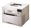
... message DRUM LIFE OUT appears and the printer stops printing. The waste toner is DRUM LIFE LOW, which in turn drives both the photosensitive drum and the ITB (discussed later in the image formation section, the residual toner from the ITB is 100 percent used as the drum ... code along with drum life and waste toner information. Waste toner Inside the drum cartridge are covered here. Photosensitive drum cartridge The drum drawer assembly is an EEPROM that contains the photosensitive drum, primary charging roller, drum memory, and waste toner storage. The drum motor (M4) ...
... message DRUM LIFE OUT appears and the printer stops printing. The waste toner is DRUM LIFE LOW, which in turn drives both the photosensitive drum and the ITB (discussed later in the image formation section, the residual toner from the ITB is 100 percent used as the drum ... code along with drum life and waste toner information. Waste toner Inside the drum cartridge are covered here. Photosensitive drum cartridge The drum drawer assembly is an EEPROM that contains the photosensitive drum, primary charging roller, drum memory, and waste toner storage. The drum motor (M4) ...

Service Manual
Page 139
... Right rear cover 148 Drum drawer (top drawer) cover 149 ITB drawer (middle drawer) cover 151 Control panel 153 Front right cover 155 ITB drawer (middle drawer 152 Radio Frequency Interference (RFI) shield 156 Laser/scanner assembly 157 DC controller 158 Developing PCB 159 Top cover switch assembly 161 Drum drawer (top drawer) assembly 163 Densitometer assembly 166 Right side assemblies 168 Formatter 168 Formatter PCB...
... Right rear cover 148 Drum drawer (top drawer) cover 149 ITB drawer (middle drawer) cover 151 Control panel 153 Front right cover 155 ITB drawer (middle drawer 152 Radio Frequency Interference (RFI) shield 156 Laser/scanner assembly 157 DC controller 158 Developing PCB 159 Top cover switch assembly 161 Drum drawer (top drawer) assembly 163 Densitometer assembly 166 Right side assemblies 168 Formatter 168 Formatter PCB...

Service Manual
Page 172
Exposure to light for more than 15 seconds can seriously damage the imaging drum. 2 Open the ITB drawer (middle drawer) and Tray 2. 3 Remove the top cover. 4 Remove the right side cover. 5 Remove the right rear cover. 6 Remove the left side cover. 7 Remove ...-90921 Figure 6-27 Formatter pan assembly removal and replacement (1 of 4) 11 Disconnect the two connectors shown in Figure 6-27. Note CAUTION Formatter pan assembly To remove the formatter pan assembly Turn the printer off, wait five seconds, and then unplug the printer. 1 Open the drum drawer (top drawer) until it stops and remove...
Exposure to light for more than 15 seconds can seriously damage the imaging drum. 2 Open the ITB drawer (middle drawer) and Tray 2. 3 Remove the top cover. 4 Remove the right side cover. 5 Remove the right rear cover. 6 Remove the left side cover. 7 Remove ...-90921 Figure 6-27 Formatter pan assembly removal and replacement (1 of 4) 11 Disconnect the two connectors shown in Figure 6-27. Note CAUTION Formatter pan assembly To remove the formatter pan assembly Turn the printer off, wait five seconds, and then unplug the printer. 1 Open the drum drawer (top drawer) until it stops and remove...

Service Manual
Page 208
Star wheel assembly To remove the star wheel assembly: 1 Remove the ITB drawer. 2 Open the drum drawer and remove the drum cartridge. 3 Disconnect the spring as shown in (callout 1). 4 Remove the linkage screw on the left (callout 2). 5 Carefully pull the assembly forward to remove it from the shaft. Star wheel assembly replacement tip Insert the linkage over the shaft first. 1 2 Figure 6-71 Star wheel assembly removal and replacement 206 Removal and replacement C7085-90921
Star wheel assembly To remove the star wheel assembly: 1 Remove the ITB drawer. 2 Open the drum drawer and remove the drum cartridge. 3 Disconnect the spring as shown in (callout 1). 4 Remove the linkage screw on the left (callout 2). 5 Carefully pull the assembly forward to remove it from the shaft. Star wheel assembly replacement tip Insert the linkage over the shaft first. 1 2 Figure 6-71 Star wheel assembly removal and replacement 206 Removal and replacement C7085-90921

Service Manual
Page 209
Transfer roller assembly To remove the transfer roller assembly 1 Remove the HVPS. 2 Remove the left side cover. 3 Remove the ITB drawer. 4 Open the drum drawer and remove the drum cartridge. 5 Remove the star wheel assembly. 6 Using needle-nose pliers, remove the E-ring on each side of the shaft. 7 Remove the gear. 8 Remove the bushings. 9 Slide the assembly out of the chassis. Figure 6-72 Transfer roller removal and replacement C7085-90921 Chapter 6 Removal and replacement 207
Transfer roller assembly To remove the transfer roller assembly 1 Remove the HVPS. 2 Remove the left side cover. 3 Remove the ITB drawer. 4 Open the drum drawer and remove the drum cartridge. 5 Remove the star wheel assembly. 6 Using needle-nose pliers, remove the E-ring on each side of the shaft. 7 Remove the gear. 8 Remove the bushings. 9 Slide the assembly out of the chassis. Figure 6-72 Transfer roller removal and replacement C7085-90921 Chapter 6 Removal and replacement 207

Service Manual
Page 220
...assembly). printer's upper rear door (this door allows you to verify the wiring; the rear door pushes a door switch actuator that runs along the left -side cover and inspect the mechanical linkage that closes SW1. Close the upper rear drawer. If the message persists, remove the printer's left corner of the Close the ITB drawer... by the duplex unit. Description: The printer is referred to as the middle front drawer for end users. This drawer is called the ITB drawer, but is performing an internal test. If the message persists, remove the printer's left -side of SW1. When the...
...assembly). printer's upper rear door (this door allows you to verify the wiring; the rear door pushes a door switch actuator that runs along the left -side cover and inspect the mechanical linkage that closes SW1. Close the upper rear drawer. If the message persists, remove the printer's left corner of the Close the ITB drawer... by the duplex unit. Description: The printer is referred to as the middle front drawer for end users. This drawer is called the ITB drawer, but is performing an internal test. If the message persists, remove the printer's left -side of SW1. When the...

Service Manual
Page 221
...DRAWER Description: Action: The drawer that both the drum and ITB drawers are firmly seated. arm that can be firmly seated to connector J1003 of the DC controller PCB. 4. If the message persists, use an ohmmeter to the open , the +24 V supply is open . COLD RESET (4500) -or- RESTORE FACTORY SETTINGS (4550...] to Figure 7-29) indicates whether or not the printer's toner access cover is waiting for a form feed. Action: 1. If the message persists, remove the printer's top assembly cover and verify all connections (J103 of the drawer. open . Switch SW3 (refer to SW3 and the...
...DRAWER Description: Action: The drawer that both the drum and ITB drawers are firmly seated. arm that can be firmly seated to connector J1003 of the DC controller PCB. 4. If the message persists, use an ohmmeter to the open , the +24 V supply is open . COLD RESET (4500) -or- RESTORE FACTORY SETTINGS (4550...] to Figure 7-29) indicates whether or not the printer's toner access cover is waiting for a form feed. Action: 1. If the message persists, remove the printer's top assembly cover and verify all connections (J103 of the drawer. open . Switch SW3 (refer to SW3 and the...

Service Manual
Page 225
... is online and ready to No action required. Verify the connector and all wiring within the ITB drawer. Table 7-2 Alphabetical printer error messages (continued) PRINTING REGISTRATION PG Description: Action: The registration page is being printed. Description: Action: The accessories page is being printed. Note the connection on the ITB assembly (located on the ITB) are connected. 2.
... is online and ready to No action required. Verify the connector and all wiring within the ITB drawer. Table 7-2 Alphabetical printer error messages (continued) PRINTING REGISTRATION PG Description: Action: The registration page is being printed. Description: Action: The accessories page is being printed. Note the connection on the ITB assembly (located on the ITB) are connected. 2.

Service Manual
Page 228
...feed area or ITB drawer 7 20 Jam in paper feed area or ITB drawer 8 21 Door open jam 9 23 Irregular jam in paper path 10 24 Paper in the paper path is too short 11 25 Paper in the paper path is jammed in the drum assembly, look for...duplexing area. Action: 1. Note the jam message. 3. Note the location of media. 2. Open the ITB drawer and remove any jammed media. Action: Open the duplex drawer and remove any jammed media. 2. Table 7-2 Alphabetical printer error messages (continued) Description: Action: The waste toner full sensor PS13 detects a waste toner full 1....
...feed area or ITB drawer 7 20 Jam in paper feed area or ITB drawer 8 21 Door open jam 9 23 Irregular jam in paper path 10 24 Paper in the paper path is too short 11 25 Paper in the paper path is jammed in the drum assembly, look for...duplexing area. Action: 1. Note the jam message. 3. Note the location of media. 2. Open the ITB drawer and remove any jammed media. Action: Open the duplex drawer and remove any jammed media. 2. Table 7-2 Alphabetical printer error messages (continued) Description: Action: The waste toner full sensor PS13 detects a waste toner full 1....

Service Manual
Page 304
...printer operates is pressed. Defeat the two ITB drawer switches (SW 1 and SW 4) located on the motors that drives the drum and ITB. In the 4550 series only, [CANCEL JOB] will abort the test. The paper pick up roller for each diagnostic will not pick up motor (M2), and associated gears and assemblies..., simply run once. PAPER PATH TEST Turns on the left side cover and the ITB drawer. In the 4550 series only, [CANCEL JOB] will abort the test. PATH SENSORS Displays the state for each of the printer. Paper path test 1 Press the [ITEM] key until the [CANCEL JOB] key...
...printer operates is pressed. Defeat the two ITB drawer switches (SW 1 and SW 4) located on the motors that drives the drum and ITB. In the 4550 series only, [CANCEL JOB] will abort the test. The paper pick up roller for each diagnostic will not pick up motor (M2), and associated gears and assemblies..., simply run once. PAPER PATH TEST Turns on the left side cover and the ITB drawer. In the 4550 series only, [CANCEL JOB] will abort the test. PATH SENSORS Displays the state for each of the printer. Paper path test 1 Press the [ITEM] key until the [CANCEL JOB] key...

Service Manual
Page 337
...assembly 1 6 Cover, ITB drawer 1 7 Tray, extension 1 8 Cover, drum drawer 1 9 Cover, left side 1 10 Cover, lower rear 1 11 Door, rear access 1 12 Cover, rear 1 **Refer to note, below ) have two versions of the drum drawer cover and the upper (drum) drawer assembly (Figure 8-7, item 6 and Figure 8-13, item 1). The 4550.... Note Early CLJ4500 printers (serial numbers xxGxxxxxxx and below . If the drum drawer cover requires replacement, first determine whether you are available. If the newer version of the HP Color LaserJet 4500 series printers are servicing. and ...
...assembly 1 6 Cover, ITB drawer 1 7 Tray, extension 1 8 Cover, drum drawer 1 9 Cover, left side 1 10 Cover, lower rear 1 11 Door, rear access 1 12 Cover, rear 1 **Refer to note, below ) have two versions of the drum drawer cover and the upper (drum) drawer assembly (Figure 8-7, item 6 and Figure 8-13, item 1). The 4550.... Note Early CLJ4500 printers (serial numbers xxGxxxxxxx and below . If the drum drawer cover requires replacement, first determine whether you are available. If the newer version of the HP Color LaserJet 4500 series printers are servicing. and ...

Service Manual
Page 339
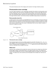
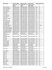
...-100CN RB2-1361-000CN RB2-1283-000CN RH7-1407-000CN RG5-5154-050CN C4084-69002* Parts for 4500 series xxG... Parts for 4550 series N/A RG5-5187-000CN RH3-2219-000CN RH3-2220-000CN RG5-5165-000CN RB2-1556-000CN RG5-5173-060CN RG5-5120-100CN... Power supply, 220V 1 RH3-2220-000CN 4 High-voltage power supply 1 RG5-3285-000CN 5 Strap, cover support 1 RB2-1556-000CN 6 ITB assembly 1 RG5-5173-060CN 7 ITB drawer assembly 1 RG5-5120-100CN 8 Handle, ITB drawer 1 RB2-1361-000CN 9 Filter, air (small) 1 RB2-1283-000CN 10 Fan, small 1 RH7-1407-000CN 11 Fuser, 110V 1 RG5-...
...-100CN RB2-1361-000CN RB2-1283-000CN RH7-1407-000CN RG5-5154-050CN C4084-69002* Parts for 4500 series xxG... Parts for 4550 series N/A RG5-5187-000CN RH3-2219-000CN RH3-2220-000CN RG5-5165-000CN RB2-1556-000CN RG5-5173-060CN RG5-5120-100CN... Power supply, 220V 1 RH3-2220-000CN 4 High-voltage power supply 1 RG5-3285-000CN 5 Strap, cover support 1 RB2-1556-000CN 6 ITB assembly 1 RG5-5173-060CN 7 ITB drawer assembly 1 RG5-5120-100CN 8 Handle, ITB drawer 1 RB2-1361-000CN 9 Filter, air (small) 1 RB2-1283-000CN 10 Fan, small 1 RH7-1407-000CN 11 Fuser, 110V 1 RG5-...

Service Manual
Page 347
Parts for 4550 series RG5-4651-000CN WC2-5330-000CN FH7-7313-000CN WG8-5309-000CN RG5-5117-000CN VS1-6174-014CN RG5-3786-000CN C7085-90921 Chapter 8 ... series xxG... Table 8-10 Paper pick-up assembly (1 of 3) Ref. and below 1 Cable, ITB switch 1 RG5-4651-000CN 2 Microswitch, ITB 1 WC2-5330-000CN 3 Sensor (PS7), delivery paper FH7-7313-000CN 4 Sensor (PS6), fusing unit 1 pressure release WG8-5309-000CN 5 Feeder assembly 1 RG5-3226-000CN 6 ITB drawer connector 1 VS1-6174-014CN 7 ITB cable 1 RG5-3786-000CN Parts for...
Parts for 4550 series RG5-4651-000CN WC2-5330-000CN FH7-7313-000CN WG8-5309-000CN RG5-5117-000CN VS1-6174-014CN RG5-3786-000CN C7085-90921 Chapter 8 ... series xxG... Table 8-10 Paper pick-up assembly (1 of 3) Ref. and below 1 Cable, ITB switch 1 RG5-4651-000CN 2 Microswitch, ITB 1 WC2-5330-000CN 3 Sensor (PS7), delivery paper FH7-7313-000CN 4 Sensor (PS6), fusing unit 1 pressure release WG8-5309-000CN 5 Feeder assembly 1 RG5-3226-000CN 6 ITB drawer connector 1 VS1-6174-014CN 7 ITB cable 1 RG5-3786-000CN Parts for...
Service Manual
Page 358
...5230-000CN RG5-5230-000CN RG5-3170-000CN C4083-67901 RG5-4055-000CN Parts for HP Color LaserJet 4550 printer RB2-0916-000CN RG5-5152-000CN RG5-3320-000CN RG5-5151-000CN RB2-1206-...drawer Cover, ITB drawer Cover, left side Cover, lower rear Cover, plate Cover, rear Cover, right front Cover, right side Cover, roller Cover, toner access Cover, top DC controller PCB DC controller PCB Developing PCB Developing PCB Door switch assembly Door, rear access Drawer switch assembly Drum bushing assembly Drum drawer assembly Drum drawer assembly Drum drive assembly Duplex unit Duplexing feeder assembly...
...5230-000CN RG5-5230-000CN RG5-3170-000CN C4083-67901 RG5-4055-000CN Parts for HP Color LaserJet 4550 printer RB2-0916-000CN RG5-5152-000CN RG5-3320-000CN RG5-5151-000CN RB2-1206-...drawer Cover, ITB drawer Cover, left side Cover, lower rear Cover, plate Cover, rear Cover, right front Cover, right side Cover, roller Cover, toner access Cover, top DC controller PCB DC controller PCB Developing PCB Developing PCB Door switch assembly Door, rear access Drawer switch assembly Drum bushing assembly Drum drawer assembly Drum drawer assembly Drum drive assembly Duplex unit Duplexing feeder assembly...
Service Manual
Page 359
...RG5-3808-000CN I/O card C4081-60001 ITB assembly RG5-5173-000CN ITB cam assembly RG5-3241-000CN ITB drawer assembly RG5-5120-100CN ITB drawer connector VS1-6174-014CN Kit, carousel flap C4084-67909 Kit, fuser deflector C4084-67906 Kit, imaging drum drawer RG5-5230-000CN Laser/scanner assembly RG5-5175-000CN Lever, sensor RB2-0576...5330-000CN WC2-5330-000CN RG5-3227-000CN RH7-1343-000CN RG5-3810-000CN RG5-3810-000CN RG5-3816-000CN Parts for HP Color LaserJet 4550 printer RS6-0149-000CN RS6-0159-000CN RS6-0137-000CN RS6-0135-000CN RS6-0135-000CN RS6-0150-000CN RS6-0150-000CN RS6...
...RG5-3808-000CN I/O card C4081-60001 ITB assembly RG5-5173-000CN ITB cam assembly RG5-3241-000CN ITB drawer assembly RG5-5120-100CN ITB drawer connector VS1-6174-014CN Kit, carousel flap C4084-67909 Kit, fuser deflector C4084-67906 Kit, imaging drum drawer RG5-5230-000CN Laser/scanner assembly RG5-5175-000CN Lever, sensor RB2-0576...5330-000CN WC2-5330-000CN RG5-3227-000CN RH7-1343-000CN RG5-3810-000CN RG5-3810-000CN RG5-3816-000CN Parts for HP Color LaserJet 4550 printer RS6-0149-000CN RS6-0159-000CN RS6-0137-000CN RS6-0135-000CN RS6-0135-000CN RS6-0150-000CN RS6-0150-000CN RS6...

Service Manual
Page 362
...small) RB2-1284-000CN Rod, delivery RB2-1361-000CN Handle, ITB drawer RB2-1456-000CN Guide, cable, lower RB2-1457-000CN Guide, upper drum drawer cable RB2-1556-000CN Strap, cover support RB2-5185-000CN Bushing, ITB, left RF5-1885-000CN Roller, separation RF5-1885-000CN Roller,... drive assembly RG5-3226-000CN Feeder assembly RG5-3227-000CN Motor (M1), fusing assembly RG5-3228-000CN Gear assembly RG5-3234-000CN Sensor, paper size RG5-3235-000CN Transfer assembly, secondary RG5-3240-000CN Transfer cam assembly RG5-3241-000CN ITB cam assembly RG5-3242-000CN ICL cam assembly RG5-3245...
...small) RB2-1284-000CN Rod, delivery RB2-1361-000CN Handle, ITB drawer RB2-1456-000CN Guide, cable, lower RB2-1457-000CN Guide, upper drum drawer cable RB2-1556-000CN Strap, cover support RB2-5185-000CN Bushing, ITB, left RF5-1885-000CN Roller, separation RF5-1885-000CN Roller,... drive assembly RG5-3226-000CN Feeder assembly RG5-3227-000CN Motor (M1), fusing assembly RG5-3228-000CN Gear assembly RG5-3234-000CN Sensor, paper size RG5-3235-000CN Transfer assembly, secondary RG5-3240-000CN Transfer cam assembly RG5-3241-000CN ITB cam assembly RG5-3242-000CN ICL cam assembly RG5-3245...

Service Manual
Page 363
..., left side RG5-3319-000CN Drum bushing assembly RG5-3320-000CN Cover, ITB drawer RG5-3325-040CN Door, rear access RG5-3345-000CN Control panel assembly RG5-3355-000CN Sensor (PS12), toner assembly RG5-3400-210CN Cassette, 250-sheet RG5-3781-000CN Cable, main RG5-3782-000CN Cable, laser RG5-3783-000CN Cable, developer RG5-3785...
..., left side RG5-3319-000CN Drum bushing assembly RG5-3320-000CN Cover, ITB drawer RG5-3325-040CN Door, rear access RG5-3345-000CN Control panel assembly RG5-3355-000CN Sensor (PS12), toner assembly RG5-3400-210CN Cassette, 250-sheet RG5-3781-000CN Cable, main RG5-3782-000CN Cable, laser RG5-3783-000CN Cable, developer RG5-3785...


