
Service Manual
Page 8
...125 Tray 1 assembly 126 Internal assemblies 130 Tray 1 pickup roller 130 Pickup sensor flag 132 Tray 1 separation pad 133 Tray 2 pickup roller 136 Tray 2 and 250-sheet feeder separation pad 139 Fan 140 Fuser 141 Laser/scanner 143 Laser/scanner plate 144 E-label reader 145 Formatter 147 Drive ...PCA 153 Solenoid 158 Access plate 159 Power supply 162 Top-output-bin delivery assembly 169 Registration-roller assembly 172 Transfer roller 174 Feed belts 175 Trays 176 250-sheet feeder and 500-sheet feeder pickup roller 176 500-sheet feeder separation pad 178 6 Contents ENWW
...125 Tray 1 assembly 126 Internal assemblies 130 Tray 1 pickup roller 130 Pickup sensor flag 132 Tray 1 separation pad 133 Tray 2 pickup roller 136 Tray 2 and 250-sheet feeder separation pad 139 Fan 140 Fuser 141 Laser/scanner 143 Laser/scanner plate 144 E-label reader 145 Formatter 147 Drive ...PCA 153 Solenoid 158 Access plate 159 Power supply 162 Top-output-bin delivery assembly 169 Registration-roller assembly 172 Transfer roller 174 Feed belts 175 Trays 176 250-sheet feeder and 500-sheet feeder pickup roller 176 500-sheet feeder separation pad 178 6 Contents ENWW

Service Manual
Page 12
...separation pad (2 of 3 134 Removing the tray 1 separation pad (3 of 3 135 Removing the tray 2 pickup roller (1 of 3 136 Removing the tray 2 pickup roller (2 of 3 137 Removing the tray 2 pickup roller (3 of 3 138 Removing the tray 2 and 250-sheet feeder separation pad 139 Removing the fan 140 Removing... the fuser (1 of 2 141 Removing the fuser (2 of 2 142 Removing the laser/scanner 143 Removing the e-...
...separation pad (2 of 3 134 Removing the tray 1 separation pad (3 of 3 135 Removing the tray 2 pickup roller (1 of 3 136 Removing the tray 2 pickup roller (2 of 3 137 Removing the tray 2 pickup roller (3 of 3 138 Removing the tray 2 and 250-sheet feeder separation pad 139 Removing the fan 140 Removing... the fuser (1 of 2 141 Removing the fuser (2 of 2 142 Removing the laser/scanner 143 Removing the e-...

Service Manual
Page 76
...and replace these parts. Variables such as media, environment, and usage can cause these parts can seriously affect the printer's performance. Periodic inspection of parts Periodic replacement parts are the parts that are found to be worn or damaged... assembly q transfer roller q separation pads (tray 1, tray 2, and tray 3) q pickup rollers (tray 1, tray 2, and tray 3) q output feed rollers (upper and lower) q transport belts and rollers See "Removal and replacement" in chapter 8 for information about suitable media, environment, and usage conditions. 74 Printer maintenance ENWW
...and replace these parts. Variables such as media, environment, and usage can cause these parts can seriously affect the printer's performance. Periodic inspection of parts Periodic replacement parts are the parts that are found to be worn or damaged... assembly q transfer roller q separation pads (tray 1, tray 2, and tray 3) q pickup rollers (tray 1, tray 2, and tray 3) q output feed rollers (upper and lower) q transport belts and rollers See "Removal and replacement" in chapter 8 for information about suitable media, environment, and usage conditions. 74 Printer maintenance ENWW

Service Manual
Page 105
...to the pickup roller. The media goes through the sheet feeder PCA. The sheet feeder pickup solenoids (SL2001, SL2002) are turned on when the following three requirements are driven by the printer and controlled by the printer's engine controller. The pickup roller makes a...printer. The paper sensor detects media. Pickup-feed paper path The main motor (M903) uses gears to the printer. The engine controller drives the solenoid at a necessary timing through the transfer, separation, and fuser/delivery blocks, and is shown). Sheet feeders HP LaserJet 2300 series printers...
...to the pickup roller. The media goes through the sheet feeder PCA. The sheet feeder pickup solenoids (SL2001, SL2002) are turned on when the following three requirements are driven by the printer and controlled by the printer's engine controller. The pickup roller makes a...printer. The paper sensor detects media. Pickup-feed paper path The main motor (M903) uses gears to the printer. The engine controller drives the solenoid at a necessary timing through the transfer, separation, and fuser/delivery blocks, and is shown). Sheet feeders HP LaserJet 2300 series printers...

Service Manual
Page 106
...(printer) PS2003: 500-sheet feeder media sensor SL2002: 500-sheet feeder pickup solenoid PS2001: 250-sheet feeder media sensor SL2001: 250-sheet feeder pickup solenoid 104 Theory of -page detection signal (/TOPSNS) Paper feeder paper detection signal (/FDSNS) Paper feeder pickup... rollers M904 Reverse motor M903 Main motor Photosensitive drum Paper feeder PCA Registration shutter Pressure roller Feed belts PS2305 Transfer charging roller Registration roller SL2002 (SL2001) Feed rollers PS2003 (PS2001) Optional tray 3 (250-sheet or 500-sheet feeder) Pickup roller Feed roller Figure...
...(printer) PS2003: 500-sheet feeder media sensor SL2002: 500-sheet feeder pickup solenoid PS2001: 250-sheet feeder media sensor SL2001: 250-sheet feeder pickup solenoid 104 Theory of -page detection signal (/TOPSNS) Paper feeder paper detection signal (/FDSNS) Paper feeder pickup... rollers M904 Reverse motor M903 Main motor Photosensitive drum Paper feeder PCA Registration shutter Pressure roller Feed belts PS2305 Transfer charging roller Registration roller SL2002 (SL2001) Feed rollers PS2003 (PS2001) Optional tray 3 (250-sheet or 500-sheet feeder) Pickup roller Feed roller Figure...

Service Manual
Page 111
...-side cover 124 Power switch 125 Tray 1 assembly 126 Internal assemblies 130 Tray 1 pickup roller 130 Pickup sensor flag 132 Tray 1 separation pad 133 Tray 2 pickup roller 136 Tray 2 and 250-sheet feeder separation pad 139 Fan 140 Fuser 141 Laser/scanner 143 Laser/scanner plate 144 E-label reader 145 Formatter 147 Drive assembly 148 Main motor...
...-side cover 124 Power switch 125 Tray 1 assembly 126 Internal assemblies 130 Tray 1 pickup roller 130 Pickup sensor flag 132 Tray 1 separation pad 133 Tray 2 pickup roller 136 Tray 2 and 250-sheet feeder separation pad 139 Fan 140 Fuser 141 Laser/scanner 143 Laser/scanner plate 144 E-label reader 145 Formatter 147 Drive assembly 148 Main motor...

Service Manual
Page 112
Trays 176 250-sheet feeder and 500-sheet feeder pickup roller 176 500-sheet feeder separation pad 178 110 Removal and replacement ENWW
Trays 176 250-sheet feeder and 500-sheet feeder pickup roller 176 500-sheet feeder separation pad 178 110 Removal and replacement ENWW

Service Manual
Page 132
Removing the tray 1 pickup roller (1 of the printer to release the tab on the cam at the right side of the pickup roller. 3 Slide the cam and the white, plastic roller toward the right side of 2) 130 Removal and replacement ENWW Figure 55. Internal assemblies Tray 1 pickup roller 1 Remove the following covers • I/O cover (see page 113) • DIMM cover (page 115) • rear cover (page 116) • front cover (page 119) 2 Use a flatblade screwdriver to release the pickup roller.
Removing the tray 1 pickup roller (1 of the printer to release the tab on the cam at the right side of the pickup roller. 3 Slide the cam and the white, plastic roller toward the right side of 2) 130 Removal and replacement ENWW Figure 55. Internal assemblies Tray 1 pickup roller 1 Remove the following covers • I/O cover (see page 113) • DIMM cover (page 115) • rear cover (page 116) • front cover (page 119) 2 Use a flatblade screwdriver to release the pickup roller.

Service Manual
Page 133
4 Rotate the pickup roller and lift it off of 2) ENWW Chapter 6 Removal and replacement 131 Figure 56. Removing the tray 1 pickup roller (2 of the pickup roller shaft.
4 Rotate the pickup roller and lift it off of 2) ENWW Chapter 6 Removal and replacement 131 Figure 56. Removing the tray 1 pickup roller (2 of the pickup roller shaft.

Service Manual
Page 138
Tray 2 pickup roller 1 Remove tray 2 and place the printer so that it rests on its rear cover. 2 Use a flatblade screwdriver to release the tab on the white, plastic lever (callout 1) at the left side of 3) 136 Removal and replacement ENWW Removing the tray 2 pickup roller (1 of the tray 2 pickup roller, and then rotate the lever to a position perpendicular to its original position. 12 Figure 61.
Tray 2 pickup roller 1 Remove tray 2 and place the printer so that it rests on its rear cover. 2 Use a flatblade screwdriver to release the tab on the white, plastic lever (callout 1) at the left side of 3) 136 Removal and replacement ENWW Removing the tray 2 pickup roller (1 of the tray 2 pickup roller, and then rotate the lever to a position perpendicular to its original position. 12 Figure 61.

Service Manual
Page 139
Figure 62. 3 Slide the lever toward the left side of the printer and through the hole to remove it. 4 Slide the pickup roller toward the left side of 3) ENWW Chapter 6 Removal and replacement 137 Removing the tray 2 pickup roller (2 of the printer.
Figure 62. 3 Slide the lever toward the left side of the printer and through the hole to remove it. 4 Slide the pickup roller toward the left side of 3) ENWW Chapter 6 Removal and replacement 137 Removing the tray 2 pickup roller (2 of the printer.

Service Manual
Page 140
5 Use a flatblade screwdriver to release the tab on the left side. Sliding the right-side lever releases the pickup roller shaft. 2 Figure 63. Removing the tray 2 pickup roller (3 of 3) 7 Lift the pickup roller out of the printer in the same manner as the lever on the lever (callout 2) at the right side of the pickup roller 6 Rotate the lever and slide it toward the right side of the printer. 138 Removal and replacement ENWW
5 Use a flatblade screwdriver to release the tab on the left side. Sliding the right-side lever releases the pickup roller shaft. 2 Figure 63. Removing the tray 2 pickup roller (3 of 3) 7 Lift the pickup roller out of the printer in the same manner as the lever on the lever (callout 2) at the right side of the pickup roller 6 Rotate the lever and slide it toward the right side of the printer. 138 Removal and replacement ENWW

Service Manual
Page 178
... photographs for removing the pickup roller from the feeder. 2 Press down the lift plate and pull the tray out of the feeder. 3 Turn the feeder so that it rests on its back side. 4 Insert the flatblade screwdriver into the slot on the right roller-shaft cover (callout 1)... 250-sheet feeder and 500-sheet feeder pickup roller Procedures for removing the pickup roller from a 250-sheet feeder are identical to the procedures for these procedures, a 500-sheet feeder is shown. 1 Lift the printer off of the feeder. 12 2 Figure 101. Removing the pickup roller from a 250-sheet or 500-sheet feeder...
... photographs for removing the pickup roller from the feeder. 2 Press down the lift plate and pull the tray out of the feeder. 3 Turn the feeder so that it rests on its back side. 4 Insert the flatblade screwdriver into the slot on the right roller-shaft cover (callout 1)... 250-sheet feeder and 500-sheet feeder pickup roller Procedures for removing the pickup roller from a 250-sheet feeder are identical to the procedures for these procedures, a 500-sheet feeder is shown. 1 Lift the printer off of the feeder. 12 2 Figure 101. Removing the pickup roller from a 250-sheet or 500-sheet feeder...

Service Manual
Page 179
... 3), and then rotate the tab towards the front of the tray to release the roller shaft. 7 Slide the lever toward the left side of the tray to remove it . ENWW Chapter 6 Removal and replacement 177 Removing the pickup roller from a 250-sheet or 500-sheet feeder (2 of 2) 8 Rotate the plastic lever... on the right side of the pickup roller shaft and then slide the lever toward the right side of the tray. 9 When the right...
... 3), and then rotate the tab towards the front of the tray to release the roller shaft. 7 Slide the lever toward the left side of the tray to remove it . ENWW Chapter 6 Removal and replacement 177 Removing the pickup roller from a 250-sheet or 500-sheet feeder (2 of 2) 8 Rotate the plastic lever... on the right side of the pickup roller shaft and then slide the lever toward the right side of the tray. 9 When the right...

Service Manual
Page 193
...XX is the jam code, Y is the device number, and Z is no jammed media, check the pickup roller and separation pad in tray X have been cleared, a sensor might be stuck or broken. XX is ... device type. XX is the jam code, Y is the device number, and Z is the device type. The printer received more data than can fit in the specified location. Check all jams have worn out. X is the number of... the tray: 2 = tray 2 3 = tray 3. Contact an HP-authorized service or support provider (see "Ordering parts and supplies and getting support" on page 205.) If ...
...XX is the jam code, Y is the device number, and Z is no jammed media, check the pickup roller and separation pad in tray X have been cleared, a sensor might be stuck or broken. XX is ... device type. XX is the jam code, Y is the device number, and Z is the device type. The printer received more data than can fit in the specified location. Check all jams have worn out. X is the number of... the tray: 2 = tray 2 3 = tray 3. Contact an HP-authorized service or support provider (see "Ordering parts and supplies and getting support" on page 205.) If ...
Service Manual
Page 210
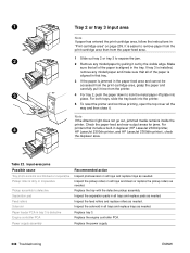
... in duplexer (HP LaserJet 2300d printer, HP LaserJet 2300dn printer, and HP LaserJet 2300dtn printer), check the duplexer area. Note If the Attention light does not go out, jammed media remains inside the printer. Table 22. Inspect the separation pads in the tray. Replace tray 3. Input-area jams Possible cause Tray photo sensors are blocked or inoperative Pickup roller is dirty or...
... in duplexer (HP LaserJet 2300d printer, HP LaserJet 2300dn printer, and HP LaserJet 2300dtn printer), check the duplexer area. Note If the Attention light does not go out, jammed media remains inside the printer. Table 22. Inspect the separation pads in the tray. Replace tray 3. Input-area jams Possible cause Tray photo sensors are blocked or inoperative Pickup roller is dirty or...

Service Manual
Page 226
...of reams directly on shelves. Print media absorbs and loses moisture rapidly. Printers using media that all printer users are responsible for wear or damage. Media stacking Consider the following areas: q pickup rollers q media guides Take extra time to evaporate. Make sure that creates... a lot of the printer is loaded correctly in the printer. Printer maintenance General cleanliness of dust and debris might require an aggressive...
...of reams directly on shelves. Print media absorbs and loses moisture rapidly. Printers using media that all printer users are responsible for wear or damage. Media stacking Consider the following areas: q pickup rollers q media guides Take extra time to evaporate. Make sure that creates... a lot of the printer is loaded correctly in the printer. Printer maintenance General cleanliness of dust and debris might require an aggressive...

Service Manual
Page 263
Table 37. Pickup assembly Ref Description Pickup assembly 1 Roller 2 Bushing, right 3 Bushing, left 4 Pickup roller 5 Arm, paper sensor Part number RM1-0332-000CN RB2-2892-000CN RB2-2895-000CN RB2-2896-000CN RB2-6304-000CN RB2-6310-000CN Quantity 1 2 1 1 1 1 ENWW Chapter 8 Parts and diagrams 261
Table 37. Pickup assembly Ref Description Pickup assembly 1 Roller 2 Bushing, right 3 Bushing, left 4 Pickup roller 5 Arm, paper sensor Part number RM1-0332-000CN RB2-2892-000CN RB2-2895-000CN RB2-2896-000CN RB2-6304-000CN RB2-6310-000CN Quantity 1 2 1 1 1 1 ENWW Chapter 8 Parts and diagrams 261

Service Manual
Page 267
Table 40. 250-sheet feeder Ref Description 250-sheet feeder Tray 2 or 250-sheet feeder (media tray only) 1 Pickup roller 2 Roller 3 Bushing, right 4 Bushing, left 14 Separation pad Part number Qty C4793-67901 1 RM1-0350-000CN 1 RB2-6304-000CN 1 RB2-2892-000CN 2 RB2-2895-000CN 1 RB2-2896-000CN 1 RC1-0954-000CN 1 ENWW Chapter 8 Parts and diagrams 265
Table 40. 250-sheet feeder Ref Description 250-sheet feeder Tray 2 or 250-sheet feeder (media tray only) 1 Pickup roller 2 Roller 3 Bushing, right 4 Bushing, left 14 Separation pad Part number Qty C4793-67901 1 RM1-0350-000CN 1 RB2-6304-000CN 1 RB2-2892-000CN 2 RB2-2895-000CN 1 RB2-2896-000CN 1 RC1-0954-000CN 1 ENWW Chapter 8 Parts and diagrams 265

Service Manual
Page 269
Table 41. 500-sheet feeder Ref Description 500-sheet feeder 1 Pickup roller 2 Roller 3 Bushing, right 4 Bushing, left 15 Pad, separation Part number Qty C7065-67901 1 RB2-6304-000CN 1 RB2-2892-000CN 2 RB2-2895-000CN 1 RB2-2896-000CN 1 RB2-9960-000CN 1 ENWW Chapter 8 Parts and diagrams 267
Table 41. 500-sheet feeder Ref Description 500-sheet feeder 1 Pickup roller 2 Roller 3 Bushing, right 4 Bushing, left 15 Pad, separation Part number Qty C7065-67901 1 RB2-6304-000CN 1 RB2-2892-000CN 2 RB2-2895-000CN 1 RB2-2896-000CN 1 RB2-9960-000CN 1 ENWW Chapter 8 Parts and diagrams 267


