HP LaserJet Printer Family - Print Media Specification Guide
Page 14
...laser printer must be printed successfully on the printer. Cutouts can interact with paper-path sensors or can be properly designed and manufactured to avoid feed or contamination problems and to a cutout location. Hewlett-Packard recommends that undergoes converting processes before it is too close to avoid wear on your HP LaserJet printer...: The area where material has been removed by offset lithography or engraving. q Avoid using paper" on HP LaserJet printers and has found that the media will not melt, vaporize, or release undesirable emissions when heated to virgin...
...laser printer must be printed successfully on the printer. Cutouts can interact with paper-path sensors or can be properly designed and manufactured to avoid feed or contamination problems and to a cutout location. Hewlett-Packard recommends that undergoes converting processes before it is too close to avoid wear on your HP LaserJet printer...: The area where material has been removed by offset lithography or engraving. q Avoid using paper" on HP LaserJet printers and has found that the media will not melt, vaporize, or release undesirable emissions when heated to virgin...
HP LaserJet Printer Family - Print Media Specification Guide
Page 15
...and free of labels, peeling. See the support documentation that cutouts are not made at a position where paper-path sensors are listed in this table generally apply to all corners of a cutout to prevent snagging or, in the support documentation that... edge rollover to prevent nesting, poor feeding, contamination, or wear on the printer. q Round all HP LaserJet printers. For more information about your printer's specifications, see the support documentation that came with your printer. CAUTION Note The following guidelines should be considered when working with a knowledgeable...
...and free of labels, peeling. See the support documentation that cutouts are not made at a position where paper-path sensors are listed in this table generally apply to all corners of a cutout to prevent snagging or, in the support documentation that... edge rollover to prevent nesting, poor feeding, contamination, or wear on the printer. q Round all HP LaserJet printers. For more information about your printer's specifications, see the support documentation that came with your printer. CAUTION Note The following guidelines should be considered when working with a knowledgeable...
HP LaserJet Printer Family - Print Media Specification Guide
Page 29
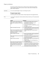
...-image curl. q Replace the paper in your printer. q Perform the printer cleaning procedures that are not well-bound to negotiate the basis weight that the paper is not near a window or a heat or air vent. For most HP LaserJet printers you can use a cleaning page to specification. ...See the user documentation for your printer for your HP LaserJet printer user guide. q Make sure that is not cut to remove build-up in your printer. q Use the correct output bin, as shown in the unit with the paper sensors. q Make sure that the paper meets the...
...-image curl. q Replace the paper in your printer. q Perform the printer cleaning procedures that are not well-bound to negotiate the basis weight that the paper is not near a window or a heat or air vent. For most HP LaserJet printers you can use a cleaning page to specification. ...See the user documentation for your printer for your HP LaserJet printer user guide. q Make sure that is not cut to remove build-up in your printer. q Use the correct output bin, as shown in the unit with the paper sensors. q Make sure that the paper meets the...

HP PCL/PJL reference - Printer Job Language Technical Reference Addendum
Page 150
... XX.XX PRINTER ERROR, CYCLE POWER XX.XX PRINTER ERROR, CYCLE POWER XX.XX PRINTER ERROR, CYCLE POWER XX.XX PRINTER ERROR, CYCLE POWER XX.XX PRINTER ERROR, CYCLE POWER XX.XX PRINTER ERROR, CYCLE POWER XX.XX PRINTER ERROR, CYCLE POWER XX.XX PRINTER ERROR, CYCLE POWER XX.XX PRINTER ERROR, CYCLE POWER ETB speed control sensor out of...
... XX.XX PRINTER ERROR, CYCLE POWER XX.XX PRINTER ERROR, CYCLE POWER XX.XX PRINTER ERROR, CYCLE POWER XX.XX PRINTER ERROR, CYCLE POWER XX.XX PRINTER ERROR, CYCLE POWER XX.XX PRINTER ERROR, CYCLE POWER XX.XX PRINTER ERROR, CYCLE POWER XX.XX PRINTER ERROR, CYCLE POWER XX.XX PRINTER ERROR, CYCLE POWER ETB speed control sensor out of...

Service Manual
Page 7
...Printer functionality and operation 73 Formatter system 74 Formatter hardware 75 Formatter subsystem 75 Engine control system 77 Engine control subsystems 78 Image formation system 80 Pickup/feed system 86 Sheet feeder 88 Media detection 90 Media detection 90 Media-size detection 90 Jam detection 91 Pickup sensors 91 Delivery sensors 91 Reversing sensors... 92 Duplexer sensors 92 Paper-feed sensor 92 6 Removal and replacement Removal and replacement strategies 95 ...
...Printer functionality and operation 73 Formatter system 74 Formatter hardware 75 Formatter subsystem 75 Engine control system 77 Engine control subsystems 78 Image formation system 80 Pickup/feed system 86 Sheet feeder 88 Media detection 90 Media detection 90 Media-size detection 90 Jam detection 91 Pickup sensors 91 Delivery sensors 91 Reversing sensors... 92 Duplexer sensors 92 Paper-feed sensor 92 6 Removal and replacement Removal and replacement strategies 95 ...
Service Manual
Page 8
... output delivery roller 126 Remove lower output delivery rollers 127 Remove laser/scanner assembly 128 Remove transport belts and rollers 130 Remove ribbon cable harness 132 Remove duplexer reverse motor 133 Remove printer drive assembly 134 Remove engine controller assembly 135 Remove main motor ...136 Remove motor plate 137 Remove printer drive assembly gears 139 Remove tray 1 pickup roller 140 Remove tray 1 pickup roller assembly 142 Remove tray 1 separation pad assembly 145 Remove tray 1 paper-sensor lever 146 Remove tray 1 solenoid 148 Remove tray 2 ...
... output delivery roller 126 Remove lower output delivery rollers 127 Remove laser/scanner assembly 128 Remove transport belts and rollers 130 Remove ribbon cable harness 132 Remove duplexer reverse motor 133 Remove printer drive assembly 134 Remove engine controller assembly 135 Remove main motor ...136 Remove motor plate 137 Remove printer drive assembly gears 139 Remove tray 1 pickup roller 140 Remove tray 1 pickup roller assembly 142 Remove tray 1 separation pad assembly 145 Remove tray 1 paper-sensor lever 146 Remove tray 1 solenoid 148 Remove tray 2 ...

Service Manual
Page 12
.... Remove EIO shield 113 Figure 81. Remove fuser assembly 116 Figure 85. Remove lower output delivery rollers 127 Figure 99. Remove the laser/scanner assembly mount screws 129 Figure 101. DIMM cover release button 99 Figure 59. Disengage the diverter locking pins 100 Figure 61. Rear... 82. Unplug wire harness 122 Figure 93. Unplug harness connectors 124 Figure 96. Pickup feed 89 Figure 51. Figure 50. Media detection sensors 90 Figure 52. Release top cover tabs (left cover latches 105 Figure 70. Release left tab shown 104 Figure 68. Unplug wire harness...
.... Remove EIO shield 113 Figure 81. Remove fuser assembly 116 Figure 85. Remove lower output delivery rollers 127 Figure 99. Remove the laser/scanner assembly mount screws 129 Figure 101. DIMM cover release button 99 Figure 59. Disengage the diverter locking pins 100 Figure 61. Rear... 82. Unplug wire harness 122 Figure 93. Unplug harness connectors 124 Figure 96. Pickup feed 89 Figure 51. Figure 50. Media detection sensors 90 Figure 52. Release top cover tabs (left cover latches 105 Figure 70. Release left tab shown 104 Figure 68. Unplug wire harness...

Service Manual
Page 13
...140 Figure 114. Remove tray 2 optic sensor and lever 155 Figure 135. Remove tray 3 (250-sheet feeder 166 Figure 147. Repetitive defect ruler 207 Figure 162. Printer paper path, sensors, and signals 220 Figure 166. General printer-component locations (1 of jams process flow 194... Figure 159. Remove tray 1 separation-pad assembly 145 Figure 121. Top down with infrared sensor port facing forward 149 Figure 125...
...140 Figure 114. Remove tray 2 optic sensor and lever 155 Figure 135. Remove tray 3 (250-sheet feeder 166 Figure 147. Repetitive defect ruler 207 Figure 162. Printer paper path, sensors, and signals 220 Figure 166. General printer-component locations (1 of jams process flow 194... Figure 159. Remove tray 1 separation-pad assembly 145 Figure 121. Top down with infrared sensor port facing forward 149 Figure 125...

Service Manual
Page 85
5 Theory of operation Chapter contents Basic operations 70 Power-on sequence 70 Basic print-period operating sequences 71 Printer timing 72 Printer functionality and operation 73 Formatter system 74 Formatter hardware 75 Formatter subsystem 75 Engine control system 77 Engine control subsystems 78 Image formation system 80 Pickup/feed system 86 Sheet feeder 88 Media detection 90 Media detection 90 Media-size detection 90 Jam detection 91 Pickup sensors 91 Delivery sensors 91 Reversing sensors 92 Duplexer sensors 92 Paper-feed sensor 92 C7058-90936 Chapter contents 69
5 Theory of operation Chapter contents Basic operations 70 Power-on sequence 70 Basic print-period operating sequences 71 Printer timing 72 Printer functionality and operation 73 Formatter system 74 Formatter hardware 75 Formatter subsystem 75 Engine control system 77 Engine control subsystems 78 Image formation system 80 Pickup/feed system 86 Sheet feeder 88 Media detection 90 Media detection 90 Media-size detection 90 Jam detection 91 Pickup sensors 91 Delivery sensors 91 Reversing sensors 92 Duplexer sensors 92 Paper-feed sensor 92 C7058-90936 Chapter contents 69

Service Manual
Page 86
... Basic operations Power-on sequence The sequence from power-on until the printer enters the standby (STBY) mode: 1 Power-on . 7 Residual paper check-After starting the main... motor, detection of residual media in the printer immediately before driving the main motor, and assesses a jam if residual media is detected. ... cartridge presence and cleans the transfer charging roller after the primary charging ac bias is detected, the printer assesses a jam or automatically delivers the residual media, according to the situation. 8 Failure or abnormality...
... Basic operations Power-on sequence The sequence from power-on until the printer enters the standby (STBY) mode: 1 Power-on . 7 Residual paper check-After starting the main... motor, detection of residual media in the printer immediately before driving the main motor, and assesses a jam if residual media is detected. ... cartridge presence and cleans the transfer charging roller after the primary charging ac bias is detected, the printer assesses a jam or automatically delivers the residual media, according to the situation. 8 Failure or abnormality...

Service Manual
Page 87
Table 25. Clears the drum surface potential and cleans the transfer charging roller. sensor detects the trailing edge of the WAIT Maintains the printer in a period until 1.2 seconds photosensitive drum in the formatter until the main motor stops rotating. Print period ... instruction command from the transfer charging the formatter, the printer roller. C7058-90936 Basic operations 71 Detects whether the cartridge is complete. page sensor. Delivers the final page out If a print instruction of the printer and cleans command is switched on the engine controller printed...
Table 25. Clears the drum surface potential and cleans the transfer charging roller. sensor detects the trailing edge of the WAIT Maintains the printer in a period until 1.2 seconds photosensitive drum in the formatter until the main motor stops rotating. Print period ... instruction command from the transfer charging the formatter, the printer roller. C7058-90936 Basic operations 71 Detects whether the cartridge is complete. page sensor. Delivers the final page out If a print instruction of the printer and cleans command is switched on the engine controller printed...

Service Manual
Page 93
... PCB Power supply PCB Reset /RSTX IC901 IC Fan motor control /BDI Formatter Sensors Solenoids Main motor Reverse motor Cooling fan Options Beam detection Scanner motor Laser/ scanner driver Figure 37. Engine control system The engine control system directly controls the... following subsystems: l laser/scanner control l paper-feed control l microswitch control l motor control l fuser-assembly control l power supply and control C7058-90936 Printer functionality and operation 77 The figure below illustrates the block diagram of...
... PCB Power supply PCB Reset /RSTX IC901 IC Fan motor control /BDI Formatter Sensors Solenoids Main motor Reverse motor Cooling fan Options Beam detection Scanner motor Laser/ scanner driver Figure 37. Engine control system The engine control system directly controls the... following subsystems: l laser/scanner control l paper-feed control l microswitch control l motor control l fuser-assembly control l power supply and control C7058-90936 Printer functionality and operation 77 The figure below illustrates the block diagram of...

Service Manual
Page 95
...is interrupted when the top cover is open. Cartridge Transfer charging roller Pressure roller Sensors Power supply PCB High-voltage power supply circut Fuser assembly fuser control circut Engine...Figure 38. This circuit supplies dc voltage (+24V, +5V, +3.3V) to the main motor, laser/scanner unit, interlock switch, formatter, solenoids, paper feeder, high-voltage power supply, and formatter. ... an overcurrent condition occurs because of the image formation system. Power supply PCB C7058-90936 Printer functionality and operation 79 l When input power is turned off then on the load side...
...is interrupted when the top cover is open. Cartridge Transfer charging roller Pressure roller Sensors Power supply PCB High-voltage power supply circut Fuser assembly fuser control circut Engine...Figure 38. This circuit supplies dc voltage (+24V, +5V, +3.3V) to the main motor, laser/scanner unit, interlock switch, formatter, solenoids, paper feeder, high-voltage power supply, and formatter. ... an overcurrent condition occurs because of the image formation system. Power supply PCB C7058-90936 Printer functionality and operation 79 l When input power is turned off then on the load side...

Service Manual
Page 102
...and the registration shutter corrects the media skew. The retransported paper is printed with one side of operation C7058-90936 The reversed paper sensor receives the paper, then signals the engine controller to the top or rear output bin unless duplex is retransported. Before the media... command to the duplex feed unit. This signal functions as a synchronization between the engine controller PCB and the formatter. To print duplex, this printer prints one side printed. The paper feed system automatically picks print media from tray 1, tray 2, or tray 3 (if installed) and delivers ...
...and the registration shutter corrects the media skew. The retransported paper is printed with one side of operation C7058-90936 The reversed paper sensor receives the paper, then signals the engine controller to the top or rear output bin unless duplex is retransported. Before the media... command to the duplex feed unit. This signal functions as a synchronization between the engine controller PCB and the formatter. To print duplex, this printer prints one side printed. The paper feed system automatically picks print media from tray 1, tray 2, or tray 3 (if installed) and delivers ...

Service Manual
Page 103
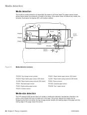
Pickup/feed system PS501: Reversed paper sensor PS503: Duplex pickup paper sensor PS2301: Delivery sensor PS3208: Tray 1 paper sensor SL1908: Cassette pickup solenoid PS502: Face-up detection signal (/FOUSNS) Delivery detection signal (/POSNS) Reverse motor drive ...CSTSNS) Duplex pickup paper detection signal (/DUPSNS) Top of -page sensor SL909: Duplex solenoid SL2908: Tray 1 pickup solenoid C7058-90936 Printer functionality and operation 87 Reversed paper detection signal (REVSNS) Face-up sensor PS1305: Cassette paper sensor PS2305: Top-of page detection signal (/TOPSNS) Tray 1 pickup...
Pickup/feed system PS501: Reversed paper sensor PS503: Duplex pickup paper sensor PS2301: Delivery sensor PS3208: Tray 1 paper sensor SL1908: Cassette pickup solenoid PS502: Face-up detection signal (/FOUSNS) Delivery detection signal (/POSNS) Reverse motor drive ...CSTSNS) Duplex pickup paper detection signal (/DUPSNS) Top of -page sensor SL909: Duplex solenoid SL2908: Tray 1 pickup solenoid C7058-90936 Printer functionality and operation 87 Reversed paper detection signal (REVSNS) Face-up sensor PS1305: Cassette paper sensor PS2305: Top-of page detection signal (/TOPSNS) Tray 1 pickup...

Service Manual
Page 104
...controlled by the printer's engine controller. The engine controller drives the solenoid at a necessary timing through the use of media is received from the formatter, the main motor (M903), reverse motor (M904), and scanner motor start of operation C7058-90936 The paper sensor detects media. The... sheet feeders are two optional sheet feeders: the 250-sheet feeder and the 500-sheet feeder. The pickup roller makes a rotation to the printer. The flow of gears.
...controlled by the printer's engine controller. The engine controller drives the solenoid at a necessary timing through the use of media is received from the formatter, the main motor (M903), reverse motor (M904), and scanner motor start of operation C7058-90936 The paper sensor detects media. The... sheet feeders are two optional sheet feeders: the 250-sheet feeder and the 500-sheet feeder. The pickup roller makes a rotation to the printer. The flow of gears.

Service Manual
Page 105
Reverse motor drive signal Main motor drive signal Top of -page sensor (printer) PS2003: Paper feeder paper sensor (500-sheet) SL2002: Paper feeder pickup solenoid (500-sheet) PS2001: Paper feeder paper sensor (250-sheet) SL2001: Paper feeder pickup solenoid (250-sheet) C7058-90936 Sheet feeder 89 Pickup feed PS2305: Top-of page detection signal (/TOPSNS...
Reverse motor drive signal Main motor drive signal Top of -page sensor (printer) PS2003: Paper feeder paper sensor (500-sheet) SL2002: Paper feeder pickup solenoid (500-sheet) PS2001: Paper feeder paper sensor (250-sheet) SL2001: Paper feeder pickup solenoid (250-sheet) C7058-90936 Sheet feeder 89 Pickup feed PS2305: Top-of page detection signal (/TOPSNS...
Service Manual
Page 106
...) SL2002: Paper feeder pickup solenoid (500-sheet) PS501: Reversed paper sensor PS503: Duplex pickup paper sensor PS2301: Delivery sensor PS2001: Paper feeder paper sensor (250-sheet) SL2001: Paper feeder pickup solenoid (250-sheet) PS502: Face-up sensor PS1305: Cassette paper sensor PS3208: Tray 1 paper sensor Media-size detection The HP LaserJet 2200 printer does not contain a media-size detection mechanism; The...
...) SL2002: Paper feeder pickup solenoid (500-sheet) PS501: Reversed paper sensor PS503: Duplex pickup paper sensor PS2301: Delivery sensor PS2001: Paper feeder paper sensor (250-sheet) SL2001: Paper feeder pickup solenoid (250-sheet) PS502: Face-up sensor PS1305: Cassette paper sensor PS3208: Tray 1 paper sensor Media-size detection The HP LaserJet 2200 printer does not contain a media-size detection mechanism; The...

Service Manual
Page 107
...readdress the pickup delay jam caused by the CPU checking for the presence of twice at the timing stored in the CPU. Pickup sensors Pickup delay jam This printer performs retry control to 270 mm: T=about 2.7 seconds l paper less than 200 mm: T=about 4.5 seconds Pickup stationary jam... A. If the top-of-page sensor (PS2305) cannot detect the media leading edge within the specified period of time (T) the printer performs the pickup operation again. If PS2305 cannot detect the media leading edge within a specified period of...
...readdress the pickup delay jam caused by the CPU checking for the presence of twice at the timing stored in the CPU. Pickup sensors Pickup delay jam This printer performs retry control to 270 mm: T=about 2.7 seconds l paper less than 200 mm: T=about 4.5 seconds Pickup stationary jam... A. If the top-of-page sensor (PS2305) cannot detect the media leading edge within the specified period of time (T) the printer performs the pickup operation again. If PS2305 cannot detect the media leading edge within a specified period of...

Service Manual
Page 108
...the reversed paper sensor (PS501) does not detect the leading edge of the forced laser emission. D. For jam detection, see "Pickup delay jam" on page 91. 92 Chapter 5 Theory of time (T) after the reversed paper sensor (PS501) detects the leading edge. Reversing sensors Reversing delay jam... for about 5.2 seconds C. When a pickup delay jam occurs-the printer enters the last rotation period to deliver the jammed media. Paper-feed sensor Paper feeder jam detection Jam detection for the printer. During pressure roller cleaning-a delivery stationary jam is same as that ...
...the reversed paper sensor (PS501) does not detect the leading edge of the forced laser emission. D. For jam detection, see "Pickup delay jam" on page 91. 92 Chapter 5 Theory of time (T) after the reversed paper sensor (PS501) detects the leading edge. Reversing sensors Reversing delay jam... for about 5.2 seconds C. When a pickup delay jam occurs-the printer enters the last rotation period to deliver the jammed media. Paper-feed sensor Paper feeder jam detection Jam detection for the printer. During pressure roller cleaning-a delivery stationary jam is same as that ...


