
Service Guide
Page 6
... board 60 USB board ...62 Power connector cable 63 Speakers ...65 Optical drive connector cable 67 Display assembly ...68 System board ...74 RTC battery ...78 Fan/heat sink assembly 79 Processor ...86 5 Setup Utility (BIOS) and System Diagnostics 89 Using Setup Utility ...89 Starting Setup Utility 89 Changing the language of...
... board 60 USB board ...62 Power connector cable 63 Speakers ...65 Optical drive connector cable 67 Display assembly ...68 System board ...74 RTC battery ...78 Fan/heat sink assembly 79 Processor ...86 5 Setup Utility (BIOS) and System Diagnostics 89 Using Setup Utility ...89 Starting Setup Utility 89 Changing the language of...

Service Guide
Page 22
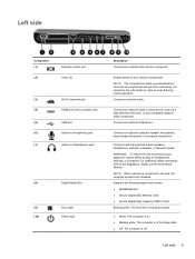
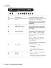
... monitor or projector. WARNING! Connects an optional computer headset microphone, stereo array microphone, or monaural microphone. It is normal for the internal fan to cool internal components. NOTE: The computer fan starts up automatically to the Regulatory, Safety, and Environmental Notices. Enable airflow to cycle on headphones, earbuds, or a headset. Left side...
... monitor or projector. WARNING! Connects an optional computer headset microphone, stereo array microphone, or monaural microphone. It is normal for the internal fan to cool internal components. NOTE: The computer fan starts up automatically to the Regulatory, Safety, and Environmental Notices. Enable airflow to cycle on headphones, earbuds, or a headset. Left side...
Service Guide
Page 24
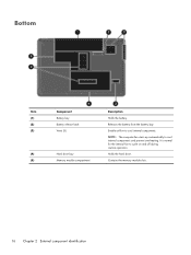
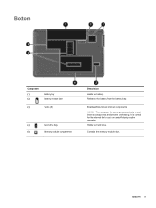
Contains the memory module slots. 16 Chapter 2 External component identification NOTE: The computer fan starts up automatically to cool internal components. Enable airflow to cool internal components and prevent overheating. Holds the hard drive. It is normal for the internal fan to cycle on and off during routine operation. Releases the battery from the battery bay. Bottom Item (1) (2) (3) (4) (5) Component Battery bay Battery release latch Vents (5) Hard drive bay Memory module compartment Description Holds the battery.
Contains the memory module slots. 16 Chapter 2 External component identification NOTE: The computer fan starts up automatically to cool internal components. Enable airflow to cool internal components and prevent overheating. Holds the hard drive. It is normal for the internal fan to cycle on and off during routine operation. Releases the battery from the battery bay. Bottom Item (1) (2) (3) (4) (5) Component Battery bay Battery release latch Vents (5) Hard drive bay Memory module compartment Description Holds the battery.
Service Guide
Page 31
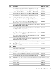
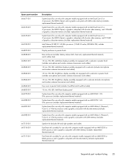
...-GHz processor (1.0-MB L2 cache, 800-MHz FSB) 534419-001 Intel Celeron SC B810 1.60-GHz processor (1.0-MB L2 cache, 800-MHz FSB) 646760-001 Fan/heat sink assembly (includes replacement thermal material): For use only with computer models equipped with an AMD Athlon II, Phenom II, Turion II, or V-Series...
...-GHz processor (1.0-MB L2 cache, 800-MHz FSB) 534419-001 Intel Celeron SC B810 1.60-GHz processor (1.0-MB L2 cache, 800-MHz FSB) 646760-001 Fan/heat sink assembly (includes replacement thermal material): For use only with computer models equipped with an AMD Athlon II, Phenom II, Turion II, or V-Series...
Service Guide
Page 42
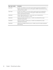
...RTC battery (includes cable and double-sided tape) Screw Kit Display Screw Kit (includes Mylar screw covers and screws) Webcam/microphone module Fan/heat sink assembly for use only with computer models equipped with an Intel Pentium processor and a graphics subsystem with discrete video memory ...(includes replacement thermal material) Fan/heat sink assembly for use only with computer models equipped with an Intel Pentium processor and a graphics subsystem with UMA video memory ...
...RTC battery (includes cable and double-sided tape) Screw Kit Display Screw Kit (includes Mylar screw covers and screws) Webcam/microphone module Fan/heat sink assembly for use only with computer models equipped with an Intel Pentium processor and a graphics subsystem with discrete video memory ...(includes replacement thermal material) Fan/heat sink assembly for use only with computer models equipped with an Intel Pentium processor and a graphics subsystem with UMA video memory ...
Service Guide
Page 43
... or V-Series processor and a graphics subsystem with UMA memory (includes replacement thermal material) Speaker Kit (includes left and right speakers and cable) Fan/heat sink assembly for use only with computer models equipped with an AMD E350 or E240 processor and a graphics subsystem with UMA memory (includes ...replacement thermal material) Fan/heat sink assembly for use only with computer models equipped with an Intel Dual Core i5 or i3 processor, the HM65 chipset, a ...
... or V-Series processor and a graphics subsystem with UMA memory (includes replacement thermal material) Speaker Kit (includes left and right speakers and cable) Fan/heat sink assembly for use only with computer models equipped with an AMD E350 or E240 processor and a graphics subsystem with UMA memory (includes ...replacement thermal material) Fan/heat sink assembly for use only with computer models equipped with an Intel Dual Core i5 or i3 processor, the HM65 chipset, a ...
Service Guide
Page 44
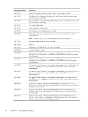
... replacement thermal material) 36 Chapter 3 Illustrated parts catalog Spare part number 647318-001 647319-001 649902-001 653337-001 653338-001 653339-001 Description Fan/heat sink assembly for use only with computer models equipped with an AMD Athlon II, Phenom II, Turion II, or V-Series processor and a... graphics subsystem with UMA memory (includes replacement thermal material) Fan/heat sink assembly for use only with computer models equipped with an AMD Athlon II, Phenom II, Turion II, or V-Series processor and a ...
... replacement thermal material) 36 Chapter 3 Illustrated parts catalog Spare part number 647318-001 647319-001 649902-001 653337-001 653338-001 653339-001 Description Fan/heat sink assembly for use only with computer models equipped with an AMD Athlon II, Phenom II, Turion II, or V-Series processor and a... graphics subsystem with UMA memory (includes replacement thermal material) Fan/heat sink assembly for use only with computer models equipped with an AMD Athlon II, Phenom II, Turion II, or V-Series processor and a ...
Service Guide
Page 83
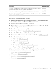
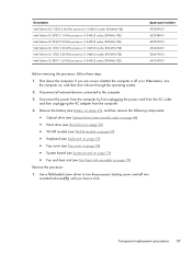
... the replacement system board: ● Memory module (see Memory module on page 49) ● RTC battery (see RTC battery on page 78) ● Fan and heat sink (see Fan/heat sink assembly on page 79) ● Processor (see Processor on , and then shut it down the computer. Remove the WLAN module (see...
... the replacement system board: ● Memory module (see Memory module on page 49) ● RTC battery (see RTC battery on page 78) ● Fan and heat sink (see Fan/heat sink assembly on page 79) ● Processor (see Processor on , and then shut it down the computer. Remove the WLAN module (see...
Service Guide
Page 87
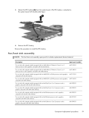
... install the RTC battery. Reverse this procedure to the system board with UMA video memory 646184-001 Component replacement procedures 79 Remove the RTC battery. Fan/heat sink assembly NOTE: The fan/heat sink assembly spare part kit includes replacement thermal material.
... install the RTC battery. Reverse this procedure to the system board with UMA video memory 646184-001 Component replacement procedures 79 Remove the RTC battery. Fan/heat sink assembly NOTE: The fan/heat sink assembly spare part kit includes replacement thermal material.
Service Guide
Page 88
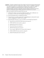
... computer is off or in ) of clearance on page 74) 80 Chapter 4 Removal and replacement procedures Before removing the fan/heat sink assembly, follow these steps: 1. The fan is controlled by a temperature sensor and is displaced through the operating system. 2. Disconnect the power from the computer by...the computer. Shut down through the ventilation grill located on , and then shut it down the computer. The computer uses an electric fan for ventilation. If you are affected by first unplugging the power cord from the AC outlet and then unplugging the AC adapter from the...
... computer is off or in ) of clearance on page 74) 80 Chapter 4 Removal and replacement procedures Before removing the fan/heat sink assembly, follow these steps: 1. The fan is controlled by a temperature sensor and is displaced through the operating system. 2. Disconnect the power from the computer by...the computer. Shut down through the ventilation grill located on , and then shut it down the computer. The computer uses an electric fan for ventilation. If you are affected by first unplugging the power cord from the AC outlet and then unplugging the AC adapter from the...
Service Guide
Page 89
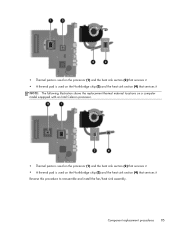
... material located between the heat sink and system board components, it may be necessary to detach it. 4. Remove the fan and heat sink (2). Loosen the captive screws (1) that secure the fan/heat sink assembly to the system board varies by computer model. NOTE: The following illustration shows the... fan/heat sink assembly removal process on a computer model equipped with the front toward you. 3. Disconnect the fan cable from side to side to move the heat sink from the system board. 2. Remove the fan/heat sink assembly: 1. NOTE: Due to ...
... material located between the heat sink and system board components, it may be necessary to detach it. 4. Remove the fan and heat sink (2). Loosen the captive screws (1) that secure the fan/heat sink assembly to the system board varies by computer model. NOTE: The following illustration shows the... fan/heat sink assembly removal process on a computer model equipped with the front toward you. 3. Disconnect the fan cable from side to side to move the heat sink from the system board. 2. Remove the fan/heat sink assembly: 1. NOTE: Due to ...
Service Guide
Page 90
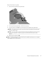
NOTE: The following illustration shows the fan/heat sink assembly removal process on a computer model equipped with an Intel processor, the Intel HM65 or HM55 chipset, and a graphics subsystem with UMA memory. 82 Chapter 4 Removal and replacement procedures NOTE: The following illustration shows the fan/heat sink assembly removal process on a computer model equipped with an Intel processor, the Intel HM65 or HM55 chipset, and a graphics subsystem with discrete memory.
NOTE: The following illustration shows the fan/heat sink assembly removal process on a computer model equipped with an Intel processor, the Intel HM65 or HM55 chipset, and a graphics subsystem with UMA memory. 82 Chapter 4 Removal and replacement procedures NOTE: The following illustration shows the fan/heat sink assembly removal process on a computer model equipped with an Intel processor, the Intel HM65 or HM55 chipset, and a graphics subsystem with discrete memory.
Service Guide
Page 91
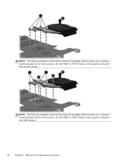
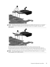
Component replacement procedures 83 NOTE: The following illustration shows the fan/heat sink assembly removal process on a computer model equipped with an AMD processor. NOTE: The following illustration shows the replacement thermal material locations on a computer ... thoroughly cleaned from the surfaces of the heat sink and the system board components each time the heat sink is included with the base enclosure, fan/heat sink assembly, processor, and system board spare part kits.
Component replacement procedures 83 NOTE: The following illustration shows the fan/heat sink assembly removal process on a computer model equipped with an AMD processor. NOTE: The following illustration shows the replacement thermal material locations on a computer ... thoroughly cleaned from the surfaces of the heat sink and the system board components each time the heat sink is included with the base enclosure, fan/heat sink assembly, processor, and system board spare part kits.
Service Guide
Page 93
... ● A thermal pad is used on the Northbridge chip (3) and the heat sink section (4) that services it Reverse this procedure to reassemble and install the fan/heat sink assembly.
... ● A thermal pad is used on the Northbridge chip (3) and the heat sink section (4) that services it Reverse this procedure to reassemble and install the fan/heat sink assembly.
Service Guide
Page 95
... Keyboard on page 53) ● Top cover (see Top cover on page 56) ● System board (see System board on page 74) ● Fan and heat sink (see Fan/heat sink assembly on , and then shut it down the computer. Use a flat-bladed screw driver to the computer. 3. Disconnect the power from...
... Keyboard on page 53) ● Top cover (see Top cover on page 56) ● System board (see System board on page 74) ● Fan and heat sink (see Fan/heat sink assembly on , and then shut it down the computer. Use a flat-bladed screw driver to the computer. 3. Disconnect the power from...
Service Guide
Page 120
... 23, 28, 34, 44 E electrostatic discharge 38 equipment guidelines 41 esc key 11 Ethernet, product description 5 external media cards, product description 6 external monitor port 14 F fan/heat sink assembly removal 79 spare part numbers 23, 34, 35, 36, 79 112 Index
... 23, 28, 34, 44 E electrostatic discharge 38 equipment guidelines 41 esc key 11 Ethernet, product description 5 external media cards, product description 6 external monitor port 14 F fan/heat sink assembly removal 79 spare part numbers 23, 34, 35, 36, 79 112 Index
Getting Started HP Notebook - Windows 7
Page 15
WARNING! NOTE: When a device is off during routine operation. NOTE: The computer fan starts up automatically to cool internal components. Enable airflow to cool internal components and prevent overheating. To reduce the risk...audio component. Connects a network cable. Connects an optional computer headset microphone, stereo array microphone, or monaural microphone. It is normal for the internal fan to the Regulatory, Safety, and Environmental Notices. Connects an optional USB device. Connects optional powered stereo speakers, headphones, earbuds, a headset, or television...
WARNING! NOTE: When a device is off during routine operation. NOTE: The computer fan starts up automatically to cool internal components. Enable airflow to cool internal components and prevent overheating. To reduce the risk...audio component. Connects a network cable. Connects an optional computer headset microphone, stereo array microphone, or monaural microphone. It is normal for the internal fan to the Regulatory, Safety, and Environmental Notices. Connects an optional USB device. Connects optional powered stereo speakers, headphones, earbuds, a headset, or television...
Getting Started HP Notebook - Windows 7
Page 17
Contains the memory module slots. Releases the battery from the battery bay. It is normal for the internal fan to cool internal components. Holds the hard drive. Enable airflow to cycle on and off during routine operation. NOTE: The computer fan starts up automatically to cool internal components and prevent overheating. Bottom 11 Bottom Component (1) (2) Battery bay Battery release latch (3) Vents (5) (4) Hard drive bay (5) Memory module compartment Description Holds the battery.
Contains the memory module slots. Releases the battery from the battery bay. It is normal for the internal fan to cool internal components. Holds the hard drive. Enable airflow to cycle on and off during routine operation. NOTE: The computer fan starts up automatically to cool internal components and prevent overheating. Bottom 11 Bottom Component (1) (2) Battery bay Battery release latch (3) Vents (5) (4) Hard drive bay (5) Memory module compartment Description Holds the battery.
HP 2000 Notebook PC - Maintenance and Service Guide
Page 6
... board ...56 USB board ...58 Power connector cable ...59 Speakers ...60 Optical drive connector cable 61 Display assembly ...62 System board ...69 RTC battery ...72 Fan/heat sink assembly ...73 Processor ...80 5 Setup Utility (BIOS) and System Diagnostics 82 Using Setup Utility ...82 Starting Setup Utility ...82 Changing the language of...
... board ...56 USB board ...58 Power connector cable ...59 Speakers ...60 Optical drive connector cable 61 Display assembly ...62 System board ...69 RTC battery ...72 Fan/heat sink assembly ...73 Processor ...80 5 Setup Utility (BIOS) and System Diagnostics 82 Using Setup Utility ...82 Starting Setup Utility ...82 Changing the language of...
HP 2000 Notebook PC - Maintenance and Service Guide
Page 20
It is normal for the internal fan to cool internal components and prevent overheating. WARNING! To reduce the risk of personal injury, adjust the volume before putting on . ● Blinking white: The ... device, such as a high-definition television, or any compatible digital or audio component. Enable airflow to the Regulatory, Safety, and Environmental Notices. NOTE: The computer fan starts up automatically to cycle on and off . 12 Chapter 2 External component identification Connect optional USB devices. Connects an optional computer headset microphone, stereo array...
It is normal for the internal fan to cool internal components and prevent overheating. WARNING! To reduce the risk of personal injury, adjust the volume before putting on . ● Blinking white: The ... device, such as a high-definition television, or any compatible digital or audio component. Enable airflow to the Regulatory, Safety, and Environmental Notices. NOTE: The computer fan starts up automatically to cycle on and off . 12 Chapter 2 External component identification Connect optional USB devices. Connects an optional computer headset microphone, stereo array...


