HP 15 Notebook PC Maintenance and Service Guide
Page 8
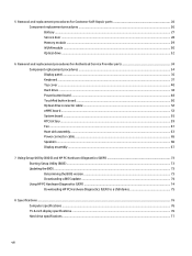
...board ...48 TouchPad button board ...50 Optical drive connector cable ...52 eMMC board ...53 System board ...55 RTC battery ...59 Fan ...61 Heat sink assembly ...63 Power connector cable ...65 Speakers ...66 Display assembly ...67 7 Using Setup Utility (BIOS) ... ...73 Updating the BIOS ...73 Determining the BIOS version ...73 Downloading a BIOS update ...74 Using HP PC Hardware Diagnostics (UEFI) ...74 Downloading HP PC Hardware Diagnostics (UEFI) to a USB device 75 8 Specifications ...76 Computer specifications ...76 15.6-inch display specifications ...76 Hard drive specifications ...77 viii
...board ...48 TouchPad button board ...50 Optical drive connector cable ...52 eMMC board ...53 System board ...55 RTC battery ...59 Fan ...61 Heat sink assembly ...63 Power connector cable ...65 Speakers ...66 Display assembly ...67 7 Using Setup Utility (BIOS) ... ...73 Updating the BIOS ...73 Determining the BIOS version ...73 Downloading a BIOS update ...74 Using HP PC Hardware Diagnostics (UEFI) ...74 Downloading HP PC Hardware Diagnostics (UEFI) to a USB device 75 8 Specifications ...76 Computer specifications ...76 15.6-inch display specifications ...76 Hard drive specifications ...77 viii
HP 15 Notebook PC Maintenance and Service Guide
Page 13
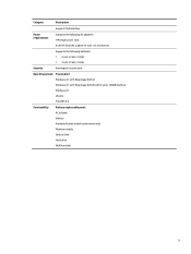
Category Description Support PS/2 interface Power requirements Supports the following AC adapters: 1M length power cord 45 W HP Smart AC adapter (3-wire, 4.5 mm barrel) Supports the following batteries: ● 4 cell, 41 Whr, 2.8 AH ● 3 cell, 31 Whr, 2.8 AH Security Kensington Security Lock Operating system Preinstalled: Windows 8.1 with...8.1 with Bing image (64 bit) with 2 years 100GB OneDrive Windows 8.1 Ubuntu FreeDOS 2.0 Serviceability End user replaceable parts: AC adapter Battery Keyboard (select model replacement only) Memory module Optical drive Hard drive WLAN module 3
Category Description Support PS/2 interface Power requirements Supports the following AC adapters: 1M length power cord 45 W HP Smart AC adapter (3-wire, 4.5 mm barrel) Supports the following batteries: ● 4 cell, 41 Whr, 2.8 AH ● 3 cell, 31 Whr, 2.8 AH Security Kensington Security Lock Operating system Preinstalled: Windows 8.1 with...8.1 with Bing image (64 bit) with 2 years 100GB OneDrive Windows 8.1 Ubuntu FreeDOS 2.0 Serviceability End user replaceable parts: AC adapter Battery Keyboard (select model replacement only) Memory module Optical drive Hard drive WLAN module 3
HP 15 Notebook PC Maintenance and Service Guide
Page 16
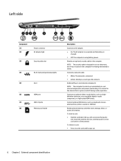
...) jack/status lights (5) Vent (6) HDMI port (7) USB 3.0 ports (8) Memory card reader Description Connects an AC adapter. ● On: The AC adapter is connected and the battery is charged. ● Off: The computer is designed to the computer. Connects a network cable. ● White: The network is connected. ● Amber: Activity is firmly... routine operation. Attaches an optional security cable to act as a deterrent, but it pops out. 6 Chapter 2 External component identification NOTE: The security cable is using battery power.
...) jack/status lights (5) Vent (6) HDMI port (7) USB 3.0 ports (8) Memory card reader Description Connects an AC adapter. ● On: The AC adapter is connected and the battery is charged. ● Off: The computer is designed to the computer. Connects a network cable. ● White: The network is connected. ● Amber: Activity is firmly... routine operation. Attaches an optional security cable to act as a deterrent, but it pops out. 6 Chapter 2 External component identification NOTE: The security cable is using battery power.
HP 15 Notebook PC Maintenance and Service Guide
Page 22
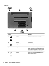
Enable airflow to cycle on and off during routine operation. It is normal for the internal fan to cool internal components. Holds the battery. NOTE: The computer fan starts up automatically to the wireless LAN (WLAN) module slot and the memory module slots. 12 Chapter 2 External component identification Provides access to cool internal components and prevent overheating. Bottom Component (1) Battery lock (2) Battery bay (3) Battery release latch (4) Vents (6) (5) Service door Description Locks and unlocks the battery in the battery bay. Releases the battery.
Enable airflow to cycle on and off during routine operation. It is normal for the internal fan to cool internal components. Holds the battery. NOTE: The computer fan starts up automatically to the wireless LAN (WLAN) module slot and the memory module slots. 12 Chapter 2 External component identification Provides access to cool internal components and prevent overheating. Bottom Component (1) Battery lock (2) Battery bay (3) Battery release latch (4) Vents (6) (5) Service door Description Locks and unlocks the battery in the battery bay. Releases the battery.
HP 15 Notebook PC Maintenance and Service Guide
Page 26
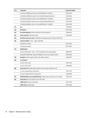
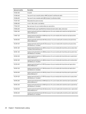
...752237-001 776906-001 776772-001 777664-001 779456-001 776777-001 776775-001 16 Chapter 3 Illustrated parts catalog Item (11) (12) (13) (14) (15) (16) (17) (18) (19) (20) (21) (22) Component Intel Core i3-4005U processor for use with Windows 8.1 Standard Intel Pentium ...8.1 Standard Intel Celeron N2830 processor for use in models without Windows 8.1 Intel Celeron N2830 processor for use with Windows 8.1 Standard Fan RTC battery Heat sink assembly (includes replacement thermal material): Power connector (includes bracket): Hard drive connector cable is available in the hardware kit, part ...
...752237-001 776906-001 776772-001 777664-001 779456-001 776777-001 776775-001 16 Chapter 3 Illustrated parts catalog Item (11) (12) (13) (14) (15) (16) (17) (18) (19) (20) (21) (22) Component Intel Core i3-4005U processor for use with Windows 8.1 Standard Intel Pentium ...8.1 Standard Intel Celeron N2830 processor for use in models without Windows 8.1 Intel Celeron N2830 processor for use with Windows 8.1 Standard Fan RTC battery Heat sink assembly (includes replacement thermal material): Power connector (includes bracket): Hard drive connector cable is available in the hardware kit, part ...
HP 15 Notebook PC Maintenance and Service Guide
Page 28
... 802.11 bgn 1×1 Wi-Fi and Bluetooth 4.0 combo adapter 2-GB memory module (PC3, 12800, 1600-MHz) 4-GB memory module (PC3, 12800, 1600-MHz) RTC battery HDMI to VGA adapter WLAN Realtek RTL8188EE 802.11bgn Wi-Fi Adapter for use on all computer models 18 Chapter 3 Illustrated parts catalog
... 802.11 bgn 1×1 Wi-Fi and Bluetooth 4.0 combo adapter 2-GB memory module (PC3, 12800, 1600-MHz) 4-GB memory module (PC3, 12800, 1600-MHz) RTC battery HDMI to VGA adapter WLAN Realtek RTL8188EE 802.11bgn Wi-Fi Adapter for use on all computer models 18 Chapter 3 Illustrated parts catalog
HP 15 Notebook PC Maintenance and Service Guide
Page 29
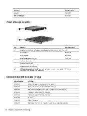
...includes 2 rubber screw covers) Speakers (include subwoofer, speaker cables, and 4 rubber isolators) 45 W HP Smart AC adapter (nPFC, RC, 3-wire, 4.5 mm), nslim Heat sink 4 cell, 41 Wh, 2.8-Ah, Li-ion battery Power cord for use in the United States, 3-pin, black, 1.00-m Power cord for use...black, 1.00-m Antenna Kit (includes left and right hinges and 2 rubber screw covers) Audio/USB port TouchPad button board (includes cable) 15.6-in the Netherlands (includes keyboard cable) Power button board (includes cable) Cover Kit (includes service door and wireless module compartment cover) Sequential ...
...includes 2 rubber screw covers) Speakers (include subwoofer, speaker cables, and 4 rubber isolators) 45 W HP Smart AC adapter (nPFC, RC, 3-wire, 4.5 mm), nslim Heat sink 4 cell, 41 Wh, 2.8-Ah, Li-ion battery Power cord for use in the United States, 3-pin, black, 1.00-m Power cord for use...black, 1.00-m Antenna Kit (includes left and right hinges and 2 rubber screw covers) Audio/USB port TouchPad button board (includes cable) 15.6-in the Netherlands (includes keyboard cable) Power button board (includes cable) Cover Kit (includes service door and wireless module compartment cover) Sequential ...
HP 15 Notebook PC Maintenance and Service Guide
Page 30
... (includes TouchPad and cable) Top cover for use in models with eMMC (includes TouchPad and cable) Webcamera/microphone module 3 cell, 31 Wh, 2.8-Ah, Li-ion battery Base enclosure for use in models without an optical drive DVD±RW Double-Layer SuperMulti Drive (includes bezel, bracket, cable, and screws) System board...
... (includes TouchPad and cable) Top cover for use in models with eMMC (includes TouchPad and cable) Webcamera/microphone module 3 cell, 31 Wh, 2.8-Ah, Li-ion battery Base enclosure for use in models without an optical drive DVD±RW Double-Layer SuperMulti Drive (includes bezel, bracket, cable, and screws) System board...
HP 15 Notebook PC Maintenance and Service Guide
Page 37
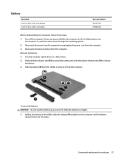
...release latch (1) to unlock the battery and slide the battery release latch (2) to remove it . Slide the battery (3) from the middle to release the battery. 3. Slide the battery in the middle, slide the battery (1) straight into the computer until the battery release latch locks into place. Disconnect... are unsure whether the computer is off the computer. Component replacement procedures 27 Battery Description 4 cell, 41-Wh, 2.8-Ah, Li-ion battery 3 cell, 31 Wh, 2.8-Ah, Li-ion battery Spare part number 752237-001 776906-001 Before disassembling the computer, follow these ...
...release latch (1) to unlock the battery and slide the battery release latch (2) to remove it . Slide the battery (3) from the middle to release the battery. 3. Slide the battery in the middle, slide the battery (1) straight into the computer until the battery release latch locks into place. Disconnect... are unsure whether the computer is off the computer. Component replacement procedures 27 Battery Description 4 cell, 41-Wh, 2.8-Ah, Li-ion battery 3 cell, 31 Wh, 2.8-Ah, Li-ion battery Spare part number 752237-001 776906-001 Before disassembling the computer, follow these ...
HP 15 Notebook PC Maintenance and Service Guide
Page 38
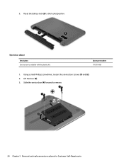
Reset the battery lock (2) to remove. 28 Chapter 5 Removal and replacement procedures for Customer Self-Repair parts Service door Description Service door is available with the plastics kit. Slide the service door (4) forward to the locked position. Lift the door (3). 3. Spare part number 776781-001 1. 2. Using a small Phillips screwdriver, loosen the service door screws (1) and (2). 2.
Reset the battery lock (2) to remove. 28 Chapter 5 Removal and replacement procedures for Customer Self-Repair parts Service door Description Service door is available with the plastics kit. Slide the service door (4) forward to the locked position. Lift the door (3). 3. Spare part number 776781-001 1. 2. Using a small Phillips screwdriver, loosen the service door screws (1) and (2). 2.
HP 15 Notebook PC Maintenance and Service Guide
Page 39
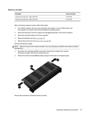
... a 45 degree angle. Remove the memory module (2) by unplugging the power cord from the computer. 4. Remove the service door (see Battery on page 28). Component replacement procedures 29 If you are unsure whether the computer is off the computer. Disconnect all external devices from the... system. 2. Reverse this procedure to release the memory module. (The memory module tilts up.) 2. Turn off or in the same slot. 1. Remove the battery (see Service door on page 27). 5. Memory module Description 4 GB memory module (PC3, 12800, 1600-MHz) 2 GB memory module (PC3, 12800, ...
... a 45 degree angle. Remove the memory module (2) by unplugging the power cord from the computer. 4. Remove the service door (see Battery on page 28). Component replacement procedures 29 If you are unsure whether the computer is off the computer. Disconnect all external devices from the... system. 2. Reverse this procedure to release the memory module. (The memory module tilts up.) 2. Turn off or in the same slot. 1. Remove the battery (see Service door on page 27). 5. Memory module Description 4 GB memory module (PC3, 12800, 1600-MHz) 2 GB memory module (PC3, 12800, ...

HP 15 Notebook PC Maintenance and Service Guide
Page 40
... computer. 3. Locate the WLAN module (1). The #2 WLAN antenna cable is connected to restore device functionality, and then contact technical support. Remove the service door (see Battery on , and then shut it down through the operating system. 2. Before removing the WLAN module, follow these steps: 1. If you are unsure whether the computer... system, replace the wireless module only with a wireless module authorized for Customer Self-Repair parts Disconnect the WLAN antenna cables (1) from the computer. 4. Remove the battery (see Service door on the WLAN module.
... computer. 3. Locate the WLAN module (1). The #2 WLAN antenna cable is connected to restore device functionality, and then contact technical support. Remove the service door (see Battery on , and then shut it down through the operating system. 2. Before removing the WLAN module, follow these steps: 1. If you are unsure whether the computer... system, replace the wireless module only with a wireless module authorized for Customer Self-Repair parts Disconnect the WLAN antenna cables (1) from the computer. 4. Remove the battery (see Service door on the WLAN module.
HP 15 Notebook PC Maintenance and Service Guide
Page 42
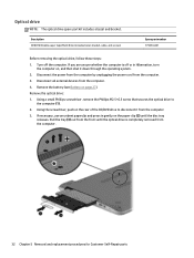
... the computer. 4. Disconnect all external devices from the computer. 3. Optical drive NOTE: The optical drive spare part kit includes a bezel and bracket. Remove the battery (see Battery on the rear of the CD/DVD drive to the computer (1). 2. If necessary, use an unbent paperclip and press in Hibernation, turn the computer on...
... the computer. 4. Disconnect all external devices from the computer. 3. Optical drive NOTE: The optical drive spare part kit includes a bezel and bracket. Remove the battery (see Battery on the rear of the CD/DVD drive to the computer (1). 2. If necessary, use an unbent paperclip and press in Hibernation, turn the computer on...
HP 15 Notebook PC Maintenance and Service Guide
Page 45
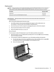
...removing the display panel, follow these steps: 1. Remove the panel: If it is necessary to replace the HP Pavilion Notebook display assembly subcomponents, see Battery on , and then shut it is necessary to the display assembly. 2. b. Disconnect all external devices from...battery (see Display assembly on page 67. Remove the plastic screw covers (1) and the two Phillips M2.5×3.0 screws (2) that secure the display bezel to replace the display bezel or any of the display bezel until the bezel disengages from the computer. 4. Description Display bezel Display panel, raw (15...
...removing the display panel, follow these steps: 1. Remove the panel: If it is necessary to replace the HP Pavilion Notebook display assembly subcomponents, see Battery on , and then shut it is necessary to the display assembly. 2. b. Disconnect all external devices from...battery (see Display assembly on page 67. Remove the plastic screw covers (1) and the two Phillips M2.5×3.0 screws (2) that secure the display bezel to replace the display bezel or any of the display bezel until the bezel disengages from the computer. 4. Description Display bezel Display panel, raw (15...
HP 15 Notebook PC Maintenance and Service Guide
Page 47
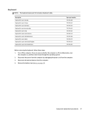
...-001 Before removing the keyboard, follow these steps: 1. Component replacement procedures 37 If you are unsure whether the computer is off the computer. Remove the battery (see Battery on , and then shut it down through the operating system. 2. Disconnect all external devices from the computer. 3. Keyboard NOTE: The keyboard spare part kit...
...-001 Before removing the keyboard, follow these steps: 1. Component replacement procedures 37 If you are unsure whether the computer is off the computer. Remove the battery (see Battery on , and then shut it down through the operating system. 2. Disconnect all external devices from the computer. 3. Keyboard NOTE: The keyboard spare part kit...
HP 15 Notebook PC Maintenance and Service Guide
Page 50
...module (see Optical drive on page 30). Shut down the computer. 2. Optical drive (see WLAN module on page 32). Remove the service door (see Battery on page 28). Disconnect all external devices connected to install the keyboard. b. e. d. Disconnect the power from the computer by first unplugging the power ...cord from the AC outlet and then unplugging the AC adapter from the computer. 4. Remove the battery (see Service door on page 27), and then remove the following components: a. Reverse this procedure to the computer. 3.
...module (see Optical drive on page 30). Shut down the computer. 2. Optical drive (see WLAN module on page 32). Remove the service door (see Battery on page 28). Disconnect all external devices connected to install the keyboard. b. e. d. Disconnect the power from the computer by first unplugging the power ...cord from the AC outlet and then unplugging the AC adapter from the computer. 4. Remove the battery (see Service door on page 27), and then remove the following components: a. Reverse this procedure to the computer. 3.
HP 15 Notebook PC Maintenance and Service Guide
Page 54
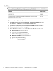
... Hard Drive Hardware Kit (not illustrated, includes hard drive rubber bracket, 2 hard drive retention brackets, and hard drive connector cable). Remove the battery (see Service door on page 29). f. Hard drive NOTE: The hard drive spare part kit includes the hard drive rubber bracket and screws.... Turn off or in the Hard Drive Hardware Kit, spare part number 732071-001. Service door (see Battery on page 40). 44 Chapter 6 Removal and replacement procedures for Authorized Service Provider parts Memory module (see Keyboard on , and then ...
... Hard Drive Hardware Kit (not illustrated, includes hard drive rubber bracket, 2 hard drive retention brackets, and hard drive connector cable). Remove the battery (see Service door on page 29). f. Hard drive NOTE: The hard drive spare part kit includes the hard drive rubber bracket and screws.... Turn off or in the Hard Drive Hardware Kit, spare part number 732071-001. Service door (see Battery on page 40). 44 Chapter 6 Removal and replacement procedures for Authorized Service Provider parts Memory module (see Keyboard on , and then ...
HP 15 Notebook PC Maintenance and Service Guide
Page 58
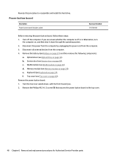
...), and then remove the following components: a. If you . 2. Disconnect the power from the computer by unplugging the power cord from the computer. 4. Remove the battery (see Battery on , and then shut it down , with the front toward you are unsure whether the computer is off the computer. c. e. Remove the power button board...
...), and then remove the following components: a. If you . 2. Disconnect the power from the computer by unplugging the power cord from the computer. 4. Remove the battery (see Battery on , and then shut it down , with the front toward you are unsure whether the computer is off the computer. c. e. Remove the power button board...
HP 15 Notebook PC Maintenance and Service Guide
Page 60
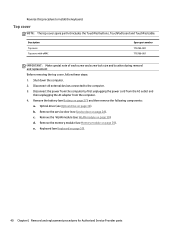
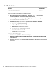
...in Hibernation, turn the computer on page 37). Disconnect the power from the computer by unplugging the power cord from the computer. 4. Remove the battery (see Keyboard on , and then shut it down , with the front toward you are unsure whether the computer is off the computer. d. Keyboard (...see Battery on page 40). Remove the Phillips M2.0×3.5 broadhead screw (2) that secures the TouchPad button board bracket to the top cover. 50 Chapter 6 Removal...
...in Hibernation, turn the computer on page 37). Disconnect the power from the computer by unplugging the power cord from the computer. 4. Remove the battery (see Keyboard on , and then shut it down , with the front toward you are unsure whether the computer is off the computer. d. Keyboard (...see Battery on page 40). Remove the Phillips M2.0×3.5 broadhead screw (2) that secures the TouchPad button board bracket to the top cover. 50 Chapter 6 Removal...
HP 15 Notebook PC Maintenance and Service Guide
Page 62
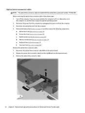
...is off the computer. Disconnect all external devices from the clip (2) built into the base enclosure. 3. d. WLAN module (see Battery on page 30). Remove the optical drive connector cable: 1. Remove the optical drive connector cable. 52 Chapter 6 Removal and replacement... procedures for Authorized Service Provider parts c. Remove the battery (see WLAN module on page 27), and then remove the following components: a. Disconnect the optical drive connector cable (1) from the computer...
...is off the computer. Disconnect all external devices from the clip (2) built into the base enclosure. 3. d. WLAN module (see Battery on page 30). Remove the optical drive connector cable: 1. Remove the optical drive connector cable. 52 Chapter 6 Removal and replacement... procedures for Authorized Service Provider parts c. Remove the battery (see WLAN module on page 27), and then remove the following components: a. Disconnect the optical drive connector cable (1) from the computer...


