HP LaserJet Printer Family - Print Media Specification Guide
Page 29
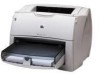
... the directions that are listed in the fuser. q Use a lighter-weight paper. set incorrectly q Make sure that the paper is not cut to the paper fibers, they can damage the printer. Paper is too smooth or too rough. For most HP LaserJet printers you can use a cleaning page to negotiate...talc and calcium carbonate. q Change the paper type or manually feed the paper into the printer. q Replace the paper in the user paper path or be able to remove build-up in your printer. Paper might not be picked up in the paper path and cause frequent paper jams....
... the directions that are listed in the fuser. q Use a lighter-weight paper. set incorrectly q Make sure that the paper is not cut to the paper fibers, they can damage the printer. Paper is too smooth or too rough. For most HP LaserJet printers you can use a cleaning page to negotiate...talc and calcium carbonate. q Change the paper type or manually feed the paper into the printer. q Replace the paper in the user paper path or be able to remove build-up in your printer. Paper might not be picked up in the paper path and cause frequent paper jams....
HP PCL/PJL reference - Printer Job Language Technical Reference Addendum
Page 122
... TRANSFER KIT ORDER FUSER KIT PERFORM PRINTER MAINTENANCE ORDER SUPPLIES PAGES LEFT REPLACE BLACK TONER REPLACE CYAN TONER REPLACE MAGENTA TONER REPLACE YELLOW TONER REPLACE IMAGE DRUM REPLACE BLACK DRUM REPLACE CYAN DRUM REPLACE MAGENTA DRUM REPLACE YELLOW DRUM REPLACE BLACK CARTRIDGE REPLACE CYAN CARTRIDGE REPLACE MAGENTA CARTRIDGE REPLACE YELLOW CARTRIDGE REPLACE TRANSPORT KIT REPLACE CLEANING KIT REPLACE TRANSFER KIT REPLACE FUSER KIT PERFORM PRINTER MAINTENANCE REPLACE SUPPLIES NON-HP SUPPLIES IN USE...
... TRANSFER KIT ORDER FUSER KIT PERFORM PRINTER MAINTENANCE ORDER SUPPLIES PAGES LEFT REPLACE BLACK TONER REPLACE CYAN TONER REPLACE MAGENTA TONER REPLACE YELLOW TONER REPLACE IMAGE DRUM REPLACE BLACK DRUM REPLACE CYAN DRUM REPLACE MAGENTA DRUM REPLACE YELLOW DRUM REPLACE BLACK CARTRIDGE REPLACE CYAN CARTRIDGE REPLACE MAGENTA CARTRIDGE REPLACE YELLOW CARTRIDGE REPLACE TRANSPORT KIT REPLACE CLEANING KIT REPLACE TRANSFER KIT REPLACE FUSER KIT PERFORM PRINTER MAINTENANCE REPLACE SUPPLIES NON-HP SUPPLIES IN USE...
HP PCL/PJL reference - Printer Job Language Technical Reference Addendum
Page 140
... ORDER TRANFER KIT ORDER FUSER KIT PERFORM PRINTER MAINTENANCE ORDER SUPPLIES PAGES LEFT REPLACE BLACK TONER REPLACE CYAN TONER REPLACE MAGENTA TONER REPLACE YELLOW TONER REPLACE IMAGE DRUM REPLACE BLACK DRUM REPLACE CYAN DRUM REPLACE MAGENTA DRUM REPLACE YELLOW DRUM REPLACE BLACK CARTRIDGE REPLACE CYAN CARTRIDGE REPLACE MAGENTA CARTRIDGE REPLACE YELLOW CARTRIDGE REPLACE TRANSPORT KIT REPLACE CLEANING KIT REPLACE TRANFER KIT REPLACE FUSER KIT PERFORM PRINTER MAINTENANCE REPLACE SUPPLIES INSTALL BLACK TONER...
... ORDER TRANFER KIT ORDER FUSER KIT PERFORM PRINTER MAINTENANCE ORDER SUPPLIES PAGES LEFT REPLACE BLACK TONER REPLACE CYAN TONER REPLACE MAGENTA TONER REPLACE YELLOW TONER REPLACE IMAGE DRUM REPLACE BLACK DRUM REPLACE CYAN DRUM REPLACE MAGENTA DRUM REPLACE YELLOW DRUM REPLACE BLACK CARTRIDGE REPLACE CYAN CARTRIDGE REPLACE MAGENTA CARTRIDGE REPLACE YELLOW CARTRIDGE REPLACE TRANSPORT KIT REPLACE CLEANING KIT REPLACE TRANFER KIT REPLACE FUSER KIT PERFORM PRINTER MAINTENANCE REPLACE SUPPLIES INSTALL BLACK TONER...
HP PCL/PJL reference - Printer Job Language Technical Reference Addendum
Page 142
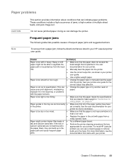
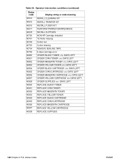
...40905 40906 40907 40908 Display string or code meaning INSTALL CLEANING KIT INSTALL TRANFER KIT INSTALL FUSER KIT PERFORM PRINTER MAINTENANCE INSTALL SUPPLIES NON-HP Cartridge Installed T2 Roller missing Croller out Croller missing REMOVE SEALING TAPE E-label cartridge error ORDER... CARTRIDGE DAYS LEFT ORDER YELLOW CARTRIDGE DAYS LEFT ORDER SUPPLIES DAYS LEFT REPLACE BLACK TONER REPLACE CYAN TONER REPLACE MAGENTA TONER REPLACE YELLOW TONER REPLACE BLACK CARTRIDGE REPLACE CYAN CARTRIDGE REPLACE MAGENTA CARTRIDGE REPLACE YELLOW CARTRIDGE REPLACE SUPPLIES 140 Chapter 4 PJL status codes ENWW
...40905 40906 40907 40908 Display string or code meaning INSTALL CLEANING KIT INSTALL TRANFER KIT INSTALL FUSER KIT PERFORM PRINTER MAINTENANCE INSTALL SUPPLIES NON-HP Cartridge Installed T2 Roller missing Croller out Croller missing REMOVE SEALING TAPE E-label cartridge error ORDER... CARTRIDGE DAYS LEFT ORDER YELLOW CARTRIDGE DAYS LEFT ORDER SUPPLIES DAYS LEFT REPLACE BLACK TONER REPLACE CYAN TONER REPLACE MAGENTA TONER REPLACE YELLOW TONER REPLACE BLACK CARTRIDGE REPLACE CYAN CARTRIDGE REPLACE MAGENTA CARTRIDGE REPLACE YELLOW CARTRIDGE REPLACE SUPPLIES 140 Chapter 4 PJL status codes ENWW

Service Manual
Page 38
...HP LaserJet 1300 print cartridge (user replaceable) Q2613A Q2613X 2,500 4,000 When print becomes faint, redistribute toner in the print cartridge. If EconoMode is used full-time when the average toner coverage is significantly less than on letter- However, HP does not recommend full-time use of EconoMode. Maintenance ENWW Printer... transfer roller RM1-0545-000CN 50,000 Can affect print quality and/or paper movement. Fuser assembly (100-127 V) RM1-0535-...
...HP LaserJet 1300 print cartridge (user replaceable) Q2613A Q2613X 2,500 4,000 When print becomes faint, redistribute toner in the print cartridge. If EconoMode is used full-time when the average toner coverage is significantly less than on letter- However, HP does not recommend full-time use of EconoMode. Maintenance ENWW Printer... transfer roller RM1-0545-000CN 50,000 Can affect print quality and/or paper movement. Fuser assembly (100-127 V) RM1-0535-...
Service Manual
Page 62
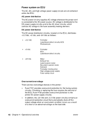
...AC power source. Power system on ECU The AC, DC, and high-voltage power supply circuits are two overvoltage devices in this printer: z Fuse F101 provides overcurrent protection for the fusing system circuitry. z In addition, the +24 Vdc and +3.3 Vdc power ...Laser/scanner motor Document scanner motor Solenoid Formatter (routing only) High voltage power supply Fuser safety circuit Overcurrent/overvoltage There are all contained within the ECU. DC power distribution The DC power distribution circuitry, located on the load side. 62 Chapter 4 - Operational overview ENWW Checking or replacing...
...AC power source. Power system on ECU The AC, DC, and high-voltage power supply circuits are two overvoltage devices in this printer: z Fuse F101 provides overcurrent protection for the fusing system circuitry. z In addition, the +24 Vdc and +3.3 Vdc power ...Laser/scanner motor Document scanner motor Solenoid Formatter (routing only) High voltage power supply Fuser safety circuit Overcurrent/overvoltage There are all contained within the ECU. DC power distribution The DC power distribution circuitry, located on the load side. 62 Chapter 4 - Operational overview ENWW Checking or replacing...
Service Manual
Page 73
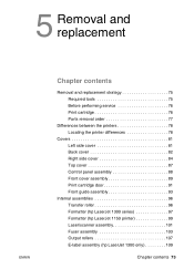
... Chapter contents Removal and replacement strategy 75 Required tools 75 Before performing service 76 Print cartridge 76 Parts removal order 77 Differences between the printers 78 Locating the printer differences 78 Covers 81 Left side cover 81 Back cover 82 Right side cover 84... 89 Print cartridge door 91 Front guide assembly 93 Internal assemblies 96 Transfer roller 96 Formatter (hp LaserJet 1300 series 97 Formatter (hp LaserJet 1150 printer 99 Laser/scanner assembly 101 Fuser assembly 103 Output rollers 107 E-label assembly (hp LaserJet 1300 only 109 Chapter contents 73
... Chapter contents Removal and replacement strategy 75 Required tools 75 Before performing service 76 Print cartridge 76 Parts removal order 77 Differences between the printers 78 Locating the printer differences 78 Covers 81 Left side cover 81 Back cover 82 Right side cover 84... 89 Print cartridge door 91 Front guide assembly 93 Internal assemblies 96 Transfer roller 96 Formatter (hp LaserJet 1300 series 97 Formatter (hp LaserJet 1150 printer 99 Laser/scanner assembly 101 Fuser assembly 103 Output rollers 107 E-label assembly (hp LaserJet 1300 only 109 Chapter contents 73
Service Manual
Page 77
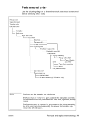
... Pickup roller Separation pad Transfer roller Left side cover Formatter Back cover Right side cover Top cover Solenoid Fan assembly (Fuser) Control panel Front cover assembly Right plate assembly (Formatter) Pickup assembly Pickup roller shaft ECU Paper lift plate assembly Paper...-feed assembly Motor Left plate assembly Laser/scanner Fuser assembly Output rollers E-label assembly (1300 series only) Note ENWW The fuser and the formatter are listed twice. To remove the fuser only, remove the left side cover. Removal and replacement strategy 77 To remove the formatter ...
... Pickup roller Separation pad Transfer roller Left side cover Formatter Back cover Right side cover Top cover Solenoid Fan assembly (Fuser) Control panel Front cover assembly Right plate assembly (Formatter) Pickup assembly Pickup roller shaft ECU Paper lift plate assembly Paper...-feed assembly Motor Left plate assembly Laser/scanner Fuser assembly Output rollers E-label assembly (1300 series only) Note ENWW The fuser and the formatter are listed twice. To remove the fuser only, remove the left side cover. Removal and replacement strategy 77 To remove the formatter ...
Service Manual
Page 104
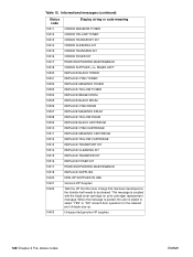
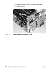
Removing the fuser assembly (2 of 4) 104 Chapter 5 - Removal and replacement ENWW 8 Remove three screws (callout 4) from the left fuser plate. 9 Remove the bracket. 4 Figure 47.
Removing the fuser assembly (2 of 4) 104 Chapter 5 - Removal and replacement ENWW 8 Remove three screws (callout 4) from the left fuser plate. 9 Remove the bracket. 4 Figure 47.
Service Manual
Page 106
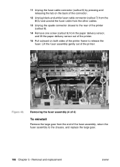
... screw (callout 9) from the end of the printer. 9 6 7 8 Figure 49. Lift the fuser assembly gently out of the fuser assembly, return the fuser assembly to release the fuser. 11 Unplug the fuser cable connector (callout 6) by pressing and releasing the tab on both sides of the printer frame to the chassis, and replace the large gear. 106 Chapter 5 -
... screw (callout 9) from the end of the printer. 9 6 7 8 Figure 49. Lift the fuser assembly gently out of the fuser assembly, return the fuser assembly to release the fuser. 11 Unplug the fuser cable connector (callout 6) by pressing and releasing the tab on both sides of the printer frame to the chassis, and replace the large gear. 106 Chapter 5 -

Service Manual
Page 108
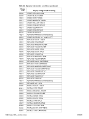
Face-up roller 1 Turn the fuser assembly over. 2 Remove the gear (callout 1) from the face-up roller and release the tab (callout 2) on the face-up roller bushing. 3 Rotate the face-up roller bushing forward until the pin releases. 4 Slide the face-up roller away from the gear side, and lift it out of 2) Reinstall note Flex the face-up roller bushing to pop the pin back into place. 108 Chapter 5 - Removal and replacement ENWW Removing the output rollers (2 of the fuser assembly. 2 1 Figure 51.
Face-up roller 1 Turn the fuser assembly over. 2 Remove the gear (callout 1) from the face-up roller and release the tab (callout 2) on the face-up roller bushing. 3 Rotate the face-up roller bushing forward until the pin releases. 4 Slide the face-up roller away from the gear side, and lift it out of 2) Reinstall note Flex the face-up roller bushing to pop the pin back into place. 108 Chapter 5 - Removal and replacement ENWW Removing the output rollers (2 of the fuser assembly. 2 1 Figure 51.
Service Manual
Page 110
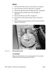
...motor To reinstall Make sure that the motor is in the correct position. Removal and replacement ENWW Motor 1 Remove the left side cover (see "Left side cover" on page...on page 82). 3 Remove the right side cover (see "Right side cover" on page 84). 4 Remove the fuser assembly (see "Fuser assembly" on page 103). 5 Remove the ECU pan (see "ECU" on page 127). 6 Disconnect the motor ...cable connector (callout 1) above and to the back of the printer. 1 2 Figure 53. The connector should be ...
...motor To reinstall Make sure that the motor is in the correct position. Removal and replacement ENWW Motor 1 Remove the left side cover (see "Left side cover" on page...on page 82). 3 Remove the right side cover (see "Right side cover" on page 84). 4 Remove the fuser assembly (see "Fuser assembly" on page 103). 5 Remove the ECU pan (see "ECU" on page 127). 6 Disconnect the motor ...cable connector (callout 1) above and to the back of the printer. 1 2 Figure 53. The connector should be ...
Service Manual
Page 126
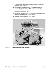
If you have not already removed the fuser, remove the fuser screw (callout 4). 12 Lift the left plate assembly 126 Chapter 5 - Removing the left plate assembly off of the printer, and slide the connector block forward and then straight out. Unthread the connector wires from the optional tray connector block at the bottom of the printer. 1 3 4 2 Figure 67. 9 Unthread the connector wires and ribbon cable from the top of the printer frame (callout 1). 10 Disconnect the connector (callout 2) from the stay. 11 Remove eight screws (callout 3). Removal and replacement ENWW
If you have not already removed the fuser, remove the fuser screw (callout 4). 12 Lift the left plate assembly 126 Chapter 5 - Removing the left plate assembly off of the printer, and slide the connector block forward and then straight out. Unthread the connector wires from the optional tray connector block at the bottom of the printer. 1 3 4 2 Figure 67. 9 Unthread the connector wires and ribbon cable from the top of the printer frame (callout 1). 10 Disconnect the connector (callout 2) from the stay. 11 Remove eight screws (callout 3). Removal and replacement ENWW

Service Manual
Page 146
... error secondary messages (continued) Message Cause Solution Fuser error. Unplug the printer and do not plug it back in for at least ten minutes. 2. Disconnect the I /O connections. 2. The RAM or ROM has an error. 1. Replace the formatter. (See "Formatter (hp LaserJet 1300 series)" on page 97 or "Formatter (hp LaserJet 1150 printer)" on page 159.) 4. Check the I /O cable and...
... error secondary messages (continued) Message Cause Solution Fuser error. Unplug the printer and do not plug it back in for at least ten minutes. 2. Disconnect the I /O connections. 2. The RAM or ROM has an error. 1. Replace the formatter. (See "Formatter (hp LaserJet 1300 series)" on page 97 or "Formatter (hp LaserJet 1150 printer)" on page 159.) 4. Check the I /O cable and...

Service Manual
Page 150
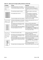
...spots on page 46.) Characters are using does not meet HP's specifications (for the HP LaserJet printer family. Make sure that the media meets specifications detailed in the Print Media Guide for the HP LaserJet printer family. Replace the print cartridge. Troubleshooting ENWW Solution Make sure that the... is damaged or has an obstruction. Clean the printer. (See "Cleaning the print path" on the surface. Vertical lines appear on the printed page. The printer needs to as dropouts). Replace the fuser. 150 Chapter 6 - The fuser is too moist or too rough). Solving print ...
...spots on page 46.) Characters are using does not meet HP's specifications (for the HP LaserJet printer family. Make sure that the media meets specifications detailed in the Print Media Guide for the HP LaserJet printer family. Replace the print cartridge. Troubleshooting ENWW Solution Make sure that the... is damaged or has an obstruction. Clean the printer. (See "Cleaning the print path" on the surface. Vertical lines appear on the printed page. The printer needs to as dropouts). Replace the fuser. 150 Chapter 6 - The fuser is too moist or too rough). Solving print ...
Service Manual
Page 151
... tray. The print cartridge needs to be replaced. The inside of the media, the media guides are using does not meet HP's specifications (for the appropriate media. Select Optimize for: in the Print Media Guide for the HP LaserJet printer family. Select the correct media through the .... Select the correct media. 2. The media basis weight is too low. The fuser temperature is too high. Table 18. The humidity level is not working correctly. Move the printer to be replaced. The toner is loose, and it is set for example, it does not ...
... tray. The print cartridge needs to be replaced. The inside of the media, the media guides are using does not meet HP's specifications (for the appropriate media. Select Optimize for: in the Print Media Guide for the HP LaserJet printer family. Select the correct media through the .... Select the correct media. 2. The media basis weight is too low. The fuser temperature is too high. Table 18. The humidity level is not working correctly. Move the printer to be replaced. The toner is loose, and it is set for example, it does not ...

Service Manual
Page 154
...pages). The fuser temperature is too long for the HP LaserJet printer family. 154 Chapter 6 - The paper's weight or surface finish does not meet HP's specifications. Remove some of the printer driver. Table...replace as the paper cools while resting on a flat surface. Solving paper-feed problems Problem Pages are missing. Paper is overfilled. Check for the HP LaserJet printer family. Open the straight-through the printer...output door on the back of the printer and use this paper path. Cause Paper curl is inherent to the laser printing processes, and occurs when paper ...
...pages). The fuser temperature is too long for the HP LaserJet printer family. 154 Chapter 6 - The paper's weight or surface finish does not meet HP's specifications. Remove some of the printer driver. Table...replace as the paper cools while resting on a flat surface. Solving paper-feed problems Problem Pages are missing. Paper is overfilled. Check for the HP LaserJet printer family. Open the straight-through the printer...output door on the back of the printer and use this paper path. Cause Paper curl is inherent to the laser printing processes, and occurs when paper ...
Service Manual
Page 159
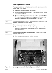
Normal resistance is 25 ohms +/- 10 ohms for the 110V printer and 80 ohms +/- 20 ohms for the heating element check Functional checks 159 To measure the continuity of the cable. If no resistance is measured, replace the fuser. 4 Remove the thermistor connector (callout 2), and measure the ... and two and between the two pins at 20° C (68° F). 5 If no resistance is measured, replace the fuser. 1 Figure 82. Normal resistance between both the printer chassis and the ECU. 3 Remove the heating element connector (callout 1) from the ECU. Note Note Heating element check Paper...
Normal resistance is 25 ohms +/- 10 ohms for the 110V printer and 80 ohms +/- 20 ohms for the heating element check Functional checks 159 To measure the continuity of the cable. If no resistance is measured, replace the fuser. 4 Remove the thermistor connector (callout 2), and measure the ... and two and between the two pins at 20° C (68° F). 5 If no resistance is measured, replace the fuser. 1 Figure 82. Normal resistance between both the printer chassis and the ECU. 3 Remove the heating element connector (callout 1) from the ECU. Note Note Heating element check Paper...

Service Manual
Page 215
... 16, 28 error light. E EconoMode 56 ECU cables 130 electrical components 197 errors 145 functions 59 jam detection operations 69 laser/scanner operations 61 loads 60 paper feeding operations 67 power system 62 removing 127 troubleshooting 140 edges, not printing 149 e-label...diagrams and part numbers 196 electrical specifications 17 electrophotographic processes operations 64, 65 testing 157 electrostatic discharge (ESD), precautions for replacing 75 fuser assembly diagrams and part numbers 202 errors 146 exit rollers 67 heating element check 159 life expectancy 38 operations 66 removing ...
... 16, 28 error light. E EconoMode 56 ECU cables 130 electrical components 197 errors 145 functions 59 jam detection operations 69 laser/scanner operations 61 loads 60 paper feeding operations 67 power system 62 removing 127 troubleshooting 140 edges, not printing 149 e-label...diagrams and part numbers 196 electrical specifications 17 electrophotographic processes operations 64, 65 testing 157 electrostatic discharge (ESD), precautions for replacing 75 fuser assembly diagrams and part numbers 202 errors 146 exit rollers 67 heating element check 159 life expectancy 38 operations 66 removing ...
Service Manual
Page 220
...feed system 67 separation pads life expectancies 38 operations 67 replacing 42 separation stage, image formation process 66 sequence operations...71 size default paper, resetting 165 margins, minimum 149 media 33 printer 16, 28 skew printed pages, troubleshooting 152, 154 specifications 18 slots... scanner assembly. See laser/scanner assembly scanning exposure stage, image formation process 65 scatter, toner 153 schedules, HP Technical Training 178 screwdrivers,... operations 67 supplies, ordering 178 support, technical 178 SupportPack, HP 23 SW301, overriding 162 switches engine test 156 paper path ...
...feed system 67 separation pads life expectancies 38 operations 67 replacing 42 separation stage, image formation process 66 sequence operations...71 size default paper, resetting 165 margins, minimum 149 media 33 printer 16, 28 skew printed pages, troubleshooting 152, 154 specifications 18 slots... scanner assembly. See laser/scanner assembly scanning exposure stage, image formation process 65 scatter, toner 153 schedules, HP Technical Training 178 screwdrivers,... operations 67 supplies, ordering 178 support, technical 178 SupportPack, HP 23 SW301, overriding 162 switches engine test 156 paper path ...


