Service Manual
Page 5
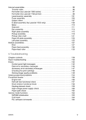
... Transfer roller 96 Formatter (hp LaserJet 1300 series 97 Formatter (hp LaserJet 1150 printer 99 Laser/scanner assembly 101 Fuser assembly 103 Output rollers 107 E-label assembly (hp LaserJet 1300 only 109 Motor 110 Solenoid 111 Fan assembly 113 Right plate assembly 115 Pickup assembly 118 Pickup roller shaft 121 Paper lift plate assembly 123 Left plate assembly 125 Bottom assemblies 127 ECU 127 Paper feed assembly 132 Paper-feed roller...
... Transfer roller 96 Formatter (hp LaserJet 1300 series 97 Formatter (hp LaserJet 1150 printer 99 Laser/scanner assembly 101 Fuser assembly 103 Output rollers 107 E-label assembly (hp LaserJet 1300 only 109 Motor 110 Solenoid 111 Fan assembly 113 Right plate assembly 115 Pickup assembly 118 Pickup roller shaft 121 Paper lift plate assembly 123 Left plate assembly 125 Bottom assemblies 127 ECU 127 Paper feed assembly 132 Paper-feed roller...
Service Manual
Page 6
... the parts lists and diagrams 183 Common hardware 183 Assembly locations 184 Covers 186 Internal assemblies 188 Internal components (1 of 2 188 Internal components (2 of 2 190 Left side plate assembly 192 Right side plate assembly 194 Electrical components 196 Paper pickup assembly 198 Paper feed guide assembly 200 Fuser assembly 202 Alphabetical parts list 204 Numerical parts list 208...
... the parts lists and diagrams 183 Common hardware 183 Assembly locations 184 Covers 186 Internal assemblies 188 Internal components (1 of 2 188 Internal components (2 of 2 190 Left side plate assembly 192 Right side plate assembly 194 Electrical components 196 Paper pickup assembly 198 Paper feed guide assembly 200 Fuser assembly 202 Alphabetical parts list 204 Numerical parts list 208...

Service Manual
Page 8
.... Figure 82. Figure 88. Figure 85. Removing the HP LaserJet 1150 printer formatter (1 of 2 99 Removing the HP LaserJet 1150 printer formatter (2 of 2 100 Removing the laser/scanner (1 of 2 101 Removing the laser/scanner (2 of 2 102 Removing the fuser assembly (1 of 4 103 Removing the fuser assembly (2 of 4 104 Removing the fuser assembly (3 of 4 105 Removing the fuser assembly (4 of 4 106 Removing the output rollers (1 of 2 107...
.... Figure 82. Figure 88. Figure 85. Removing the HP LaserJet 1150 printer formatter (1 of 2 99 Removing the HP LaserJet 1150 printer formatter (2 of 2 100 Removing the laser/scanner (1 of 2 101 Removing the laser/scanner (2 of 2 102 Removing the fuser assembly (1 of 4 103 Removing the fuser assembly (2 of 4 104 Removing the fuser assembly (3 of 4 105 Removing the fuser assembly (4 of 4 106 Removing the output rollers (1 of 2 107...

Service Manual
Page 9
...LEDs, jumpers, and switches 175 Figure 95. Right side plate assembly 194 Figure 101. Paper feed guide assembly 200 Figure 104. Main wiring (1 of 2 188 Figure 98. Electrical components 196 Figure 102. Paper pickup assembly 198 Figure 103. Internal components (1 of 2 171 Figure 91...Locations of 2 172 Figure 92. Assembly locations 184 Figure 96. Main wiring (2 of printer connectors 174 Figure 94. Covers 186 Figure 97. Figure 89. Optional paper feeder wiring 173 Figure 93. Left side plate assembly 192 Figure 100. Fuser assembly 202 ENWW ix Repetitive image defect ...
...LEDs, jumpers, and switches 175 Figure 95. Right side plate assembly 194 Figure 101. Paper feed guide assembly 200 Figure 104. Main wiring (1 of 2 188 Figure 98. Electrical components 196 Figure 102. Paper pickup assembly 198 Figure 103. Internal components (1 of 2 171 Figure 91...Locations of 2 172 Figure 92. Assembly locations 184 Figure 96. Main wiring (2 of printer connectors 174 Figure 94. Covers 186 Figure 97. Figure 89. Optional paper feeder wiring 173 Figure 93. Left side plate assembly 192 Figure 100. Fuser assembly 202 ENWW ix Repetitive image defect ...

Service Manual
Page 11
... specifications 16 Environmental specifications 16 Power specifications 17 Performance of HP LaserJet 1150 printer 17 Performance of HP LaserJet 1300 series printer 17 Print operating acoustical emissions specifications 18 Skew specifications 18 HP hardware product numbers 23 Control panel light messages 30 Media ... websites 178 Accessories 179 Common fasteners 183 Printer assemblies 185 Covers 187 Internal components (1 of 2 189 Internal components (2 of 2 191 Electrical components 197 Paper pickup assembly 199 Fuser assembly 203 Alphabetical parts list 204 Numerical parts ...
... specifications 16 Environmental specifications 16 Power specifications 17 Performance of HP LaserJet 1150 printer 17 Performance of HP LaserJet 1300 series printer 17 Print operating acoustical emissions specifications 18 Skew specifications 18 HP hardware product numbers 23 Control panel light messages 30 Media ... websites 178 Accessories 179 Common fasteners 183 Printer assemblies 185 Covers 187 Internal components (1 of 2 189 Internal components (2 of 2 191 Electrical components 197 Paper pickup assembly 199 Fuser assembly 203 Alphabetical parts list 204 Numerical parts ...

Service Manual
Page 38
...of five percent toner coverage and a medium density setting. Maintenance ENWW Printer separation pad RF0-1014-000CN 50,000 Can affect paper movement. or A4-sized paper with an average of EconoMode. HP LaserJet 1300 print cartridge (user replaceable) Q2613A Q2613X 2,500 4,000 When print becomes... toner coverage is significantly less than on letter- Printer pickup roller RL1-0303-000CN 50,000 Look for replacing components. Fuser assembly (100-127 V) RM1-0535-000CN 50,000 Can affect print quality and paper movement. Fuser assembly (220-240 V) RM1-0536-000CN 50,000 ...
...of five percent toner coverage and a medium density setting. Maintenance ENWW Printer separation pad RF0-1014-000CN 50,000 Can affect paper movement. or A4-sized paper with an average of EconoMode. HP LaserJet 1300 print cartridge (user replaceable) Q2613A Q2613X 2,500 4,000 When print becomes... toner coverage is significantly less than on letter- Printer pickup roller RL1-0303-000CN 50,000 Look for replacing components. Fuser assembly (100-127 V) RM1-0535-000CN 50,000 Can affect print quality and paper movement. Fuser assembly (220-240 V) RM1-0536-000CN 50,000 ...
Service Manual
Page 62
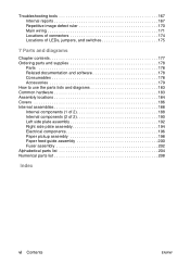
...voltage power supply circuits are two overvoltage devices in this printer: z Fuse F101 provides overcurrent protection for the fusing system circuitry. Fuse F102 provides overcurrent protection to the fuser assembly heating element. Operational overview ENWW AC voltage is connected...z +3.3 Vdc: Formatter Laser/beam detect circuitry ECU Photosensors z +5 Vdc: Formatter ECU Laser/beam detect circuitry z +24 Vdc: Motor Exhaust fan Laser/scanner motor Document scanner motor Solenoid Formatter (routing only) High voltage power supply Fuser safety circuit Overcurrent/overvoltage ...
...voltage power supply circuits are two overvoltage devices in this printer: z Fuse F101 provides overcurrent protection for the fusing system circuitry. Fuse F102 provides overcurrent protection to the fuser assembly heating element. Operational overview ENWW AC voltage is connected...z +3.3 Vdc: Formatter Laser/beam detect circuitry ECU Photosensors z +5 Vdc: Formatter ECU Laser/beam detect circuitry z +24 Vdc: Motor Exhaust fan Laser/scanner motor Document scanner motor Solenoid Formatter (routing only) High voltage power supply Fuser safety circuit Overcurrent/overvoltage ...

Service Manual
Page 67
... the printer receives a print job: Step 2 The ECU enables the laser/scanner assembly and the motor. Step 3 The paper pickup roller rotates once. Step 7 After the image is transferred, the media enters the fuser assembly where heat from the fuser and pressure... where the toner image on the page. The paper lift plate pushes the media against the pickup roller. Printer paper-feed system Step 1 The main input tray and the priority input tray merge into one sheet is fed...that media has successfully moved out of the fusing area. Step 8 The fuser assembly exit rollers deliver media to the feed...
... the printer receives a print job: Step 2 The ECU enables the laser/scanner assembly and the motor. Step 3 The paper pickup roller rotates once. Step 7 After the image is transferred, the media enters the fuser assembly where heat from the fuser and pressure... where the toner image on the page. The paper lift plate pushes the media against the pickup roller. Printer paper-feed system Step 1 The main input tray and the priority input tray merge into one sheet is fed...that media has successfully moved out of the fusing area. Step 8 The fuser assembly exit rollers deliver media to the feed...
Service Manual
Page 73
... Left side cover 81 Back cover 82 Right side cover 84 Top cover 87 Control panel assembly 88 Front cover assembly 89 Print cartridge door 91 Front guide assembly 93 Internal assemblies 96 Transfer roller 96 Formatter (hp LaserJet 1300 series 97 Formatter (hp LaserJet 1150 printer 99 Laser/scanner assembly 101 Fuser assembly 103 Output rollers 107 E-label assembly (hp LaserJet 1300 only 109 Chapter contents 73
... Left side cover 81 Back cover 82 Right side cover 84 Top cover 87 Control panel assembly 88 Front cover assembly 89 Print cartridge door 91 Front guide assembly 93 Internal assemblies 96 Transfer roller 96 Formatter (hp LaserJet 1300 series 97 Formatter (hp LaserJet 1150 printer 99 Laser/scanner assembly 101 Fuser assembly 103 Output rollers 107 E-label assembly (hp LaserJet 1300 only 109 Chapter contents 73
Service Manual
Page 77
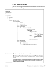
... cover Formatter Back cover Right side cover Top cover Solenoid Fan assembly (Fuser) Control panel Front cover assembly Right plate assembly (Formatter) Pickup assembly Pickup roller shaft ECU Paper lift plate assembly Paper-feed assembly Motor Left plate assembly Laser/scanner Fuser assembly Output rollers E-label assembly (1300 series only) Note ENWW The fuser and the formatter are listed twice. To remove the formatter...
... cover Formatter Back cover Right side cover Top cover Solenoid Fan assembly (Fuser) Control panel Front cover assembly Right plate assembly (Formatter) Pickup assembly Pickup roller shaft ECU Paper lift plate assembly Paper-feed assembly Motor Left plate assembly Laser/scanner Fuser assembly Output rollers E-label assembly (1300 series only) Note ENWW The fuser and the formatter are listed twice. To remove the formatter...
Service Manual
Page 103
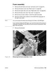
... realign the 69T gear, you must first remove the pressure roller gear. Removing the fuser assembly (1 of 4) ENWW Internal assemblies 103 You can access the third screw through the holes in the 69Tgear. Note Fuser assembly 1 Remove the left side cover (see "Left side cover" on page 81). ...cover (see "Top cover" on the right fuser plate. Release the tab (callout 3) and remove the pressure roller gear from behind the large gear on page 87). 5 Remove two screws (callout 1) from the right fuser plate. 6 Remove a third screw (callout 2) from the printer. 7 Remove the bracket. 1 2 3 Figure...
... realign the 69T gear, you must first remove the pressure roller gear. Removing the fuser assembly (1 of 4) ENWW Internal assemblies 103 You can access the third screw through the holes in the 69Tgear. Note Fuser assembly 1 Remove the left side cover (see "Left side cover" on page 81). ...cover (see "Top cover" on the right fuser plate. Release the tab (callout 3) and remove the pressure roller gear from behind the large gear on page 87). 5 Remove two screws (callout 1) from the right fuser plate. 6 Remove a third screw (callout 2) from the printer. 7 Remove the bracket. 1 2 3 Figure...
Service Manual
Page 104
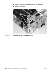
Removing the fuser assembly (2 of 4) 104 Chapter 5 - 8 Remove three screws (callout 4) from the left fuser plate. 9 Remove the bracket. 4 Figure 47. Removal and replacement ENWW
Removing the fuser assembly (2 of 4) 104 Chapter 5 - 8 Remove three screws (callout 4) from the left fuser plate. 9 Remove the bracket. 4 Figure 47. Removal and replacement ENWW

Service Manual
Page 105
Removing the fuser assembly (3 of the printer. 5 Figure 48. 10 Remove two screws (callout 5), one from each side of 4) ENWW Internal assemblies 105
Removing the fuser assembly (3 of the printer. 5 Figure 48. 10 Remove two screws (callout 5), one from each side of 4) ENWW Internal assemblies 105
Service Manual
Page 106
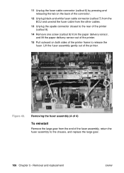
...the ECU and unwind the fuser cable from the other cables. 13 Unplug the spade connector closest to the rear of the printer (callout 8). 14 Remove one screw (callout 9) from the end of the fuser assembly, return the fuser assembly to release the fuser. 11 Unplug the fuser cable connector (callout 6) ...by pressing and releasing the tab on both sides of the printer frame to the chassis, ...
...the ECU and unwind the fuser cable from the other cables. 13 Unplug the spade connector closest to the rear of the printer (callout 8). 14 Remove one screw (callout 9) from the end of the fuser assembly, return the fuser assembly to release the fuser. 11 Unplug the fuser cable connector (callout 6) ...by pressing and releasing the tab on both sides of the printer frame to the chassis, ...
Service Manual
Page 107
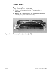
Output rollers Face-down delivery assembly 1 Remove the fuser assembly (see "Fuser assembly" on page 103). 2 Remove two screws (callout 1) and lift the face-down delivery assembly away from the fuser assembly. 1 Figure 50. Removing the output rollers (1 of 2) ENWW Internal assemblies 107
Output rollers Face-down delivery assembly 1 Remove the fuser assembly (see "Fuser assembly" on page 103). 2 Remove two screws (callout 1) and lift the face-down delivery assembly away from the fuser assembly. 1 Figure 50. Removing the output rollers (1 of 2) ENWW Internal assemblies 107

Service Manual
Page 108
Removing the output rollers (2 of the fuser assembly. 2 1 Figure 51. Removal and replacement ENWW Face-up roller 1 Turn the fuser assembly over. 2 Remove the gear (callout 1) from the gear side, and lift it out of 2) Reinstall note Flex the face-up roller away from the face-up roller and release the tab (callout 2) on the face-up roller bushing. 3 Rotate the face-up roller bushing forward until the pin releases. 4 Slide the face-up roller bushing to pop the pin back into place. 108 Chapter 5 -
Removing the output rollers (2 of the fuser assembly. 2 1 Figure 51. Removal and replacement ENWW Face-up roller 1 Turn the fuser assembly over. 2 Remove the gear (callout 1) from the gear side, and lift it out of 2) Reinstall note Flex the face-up roller away from the face-up roller and release the tab (callout 2) on the face-up roller bushing. 3 Rotate the face-up roller bushing forward until the pin releases. 4 Slide the face-up roller bushing to pop the pin back into place. 108 Chapter 5 -
Service Manual
Page 109
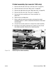
...assembly (hp LaserJet 1300 only) 1 Remove the left side cover (see "Left side cover" on page 81). 2 Remove the back cover (see "Back cover" on page 82). 3 Remove the right side cover (see "Right side cover" on page 84). 4 Remove the top cover (see "Top cover" on page 87). 5 Remove the fuser assembly (see "Fuser assembly..." on page 103). 6 Open the print cartridge door. 7 Reach under the laser/scanner plate, and grasp the e-label assembly (callout 1), which is attached to the bottom of the laser/ scanner plate. 8 Unhook the two tabs...
...assembly (hp LaserJet 1300 only) 1 Remove the left side cover (see "Left side cover" on page 81). 2 Remove the back cover (see "Back cover" on page 82). 3 Remove the right side cover (see "Right side cover" on page 84). 4 Remove the top cover (see "Top cover" on page 87). 5 Remove the fuser assembly (see "Fuser assembly..." on page 103). 6 Open the print cartridge door. 7 Reach under the laser/scanner plate, and grasp the e-label assembly (callout 1), which is attached to the bottom of the laser/ scanner plate. 8 Unhook the two tabs...
Service Manual
Page 110
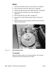
... right side cover (see "Right side cover" on page 84). 4 Remove the fuser assembly (see "Fuser assembly" on page 103). 5 Remove the ECU pan (see "ECU" on page 127). 6 Disconnect the motor cable connector (callout 1) above and to the back of the printer. 1 2 Figure 53. The connector should be above the motor. 7 Remove the three...
... right side cover (see "Right side cover" on page 84). 4 Remove the fuser assembly (see "Fuser assembly" on page 103). 5 Remove the ECU pan (see "ECU" on page 127). 6 Disconnect the motor cable connector (callout 1) above and to the back of the printer. 1 2 Figure 53. The connector should be above the motor. 7 Remove the three...
Service Manual
Page 115
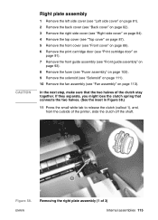
...lose the clutch spring that the two halves of the clutch stay together. ENWW Removing the right plate assembly (1 of the printer, slide the clutch off the shaft. 1 Figure 58. CAUTION Right plate assembly 1 Remove the left side cover (see "Left side cover" on page 81). 2 Remove the ...Print cartridge door" on page 91). 7 Remove the front guide assembly (see "Front guide assembly" on page 93). 8 Remove the fuser (see "Fuser assembly" on page 103). 9 Remove the solenoid (see "Solenoid" on page 111). 10 Remove the fan assembly (see "Fan assembly" on page 113). In the next step, make sure that...
...lose the clutch spring that the two halves of the clutch stay together. ENWW Removing the right plate assembly (1 of the printer, slide the clutch off the shaft. 1 Figure 58. CAUTION Right plate assembly 1 Remove the left side cover (see "Left side cover" on page 81). 2 Remove the ...Print cartridge door" on page 91). 7 Remove the front guide assembly (see "Front guide assembly" on page 93). 8 Remove the fuser (see "Fuser assembly" on page 103). 9 Remove the solenoid (see "Solenoid" on page 111). 10 Remove the fan assembly (see "Fan assembly" on page 113). In the next step, make sure that...

Service Manual
Page 146
...-sheet paper feeder is installed (HP LaserJet 1300), verify that the fuser connector and the thermistor connector are correct and the error persists, replace the fuser. (See "Fuser assembly" on page 99.) Fan error. 1. Fatal error secondary messages (continued) Message Cause Solution Fuser error. Unplug the printer, remove any optional memory, and turn the printer back on page 159.) 4. Unplug...
...-sheet paper feeder is installed (HP LaserJet 1300), verify that the fuser connector and the thermistor connector are correct and the error persists, replace the fuser. (See "Fuser assembly" on page 99.) Fan error. 1. Fatal error secondary messages (continued) Message Cause Solution Fuser error. Unplug the printer, remove any optional memory, and turn the printer back on page 159.) 4. Unplug...


