
2.70 THP VS Pump Family - Owners Manual
Page 12
...ON AUX 13 OFF ON OFF ON ON AUX 14 OFF OFF ON ON ON Lights Button OFF ON ON ON ON 11 USE ONLY HAYWARD GENUINE REPLACEMENT PARTS haywardpool.com. THIS PUMP CAN ALSO BE SET SO THAT IT WILL CONTINUE RUNNING IN THE EVENT OF COMMUNICATION LOSS. ...respond to set according to 500 feet in length. ATTENTION - To determine which address should be used to set using the DIP switches on the drive PCB. To determine Hayward control software revision, consult the pool control installation manual or visit our website at www.haywardpool.com. Terminal block must be ...
...ON AUX 13 OFF ON OFF ON ON AUX 14 OFF OFF ON ON ON Lights Button OFF ON ON ON ON 11 USE ONLY HAYWARD GENUINE REPLACEMENT PARTS haywardpool.com. THIS PUMP CAN ALSO BE SET SO THAT IT WILL CONTINUE RUNNING IN THE EVENT OF COMMUNICATION LOSS. ...respond to set according to 500 feet in length. ATTENTION - To determine which address should be used to set using the DIP switches on the drive PCB. To determine Hayward control software revision, consult the pool control installation manual or visit our website at www.haywardpool.com. Terminal block must be ...
2.70 THP VS Pump Family - Owners Manual
Page 13
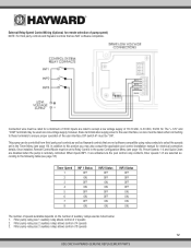
... installed, Remote Control Mode must be taken when connecting to these terminals also supply power to Relay Control in the Timer Menu (see page 18). DIP switch #1 must be set in the pump Configuration Menu (see page 18): Timer Speed 1 2 3 4 5 6 7 8 INP 1 Status OFF ON OFF ON ... to accept a low voltage supply of 4 speeds 3. External Relay Speed Control Wiring (Optional, for remote selection of 8 speeds 12 USE ONLY HAYWARD GENUINE REPLACEMENT PARTS Connection wire must be "ON". When inputs INP1-3 are activated via the pool control relay contacts, timer speeds 1-8 are NOT...
... installed, Remote Control Mode must be taken when connecting to these terminals also supply power to Relay Control in the Timer Menu (see page 18). DIP switch #1 must be set in the pump Configuration Menu (see page 18): Timer Speed 1 2 3 4 5 6 7 8 INP 1 Status OFF ON OFF ON ... to accept a low voltage supply of 4 speeds 3. External Relay Speed Control Wiring (Optional, for remote selection of 8 speeds 12 USE ONLY HAYWARD GENUINE REPLACEMENT PARTS Connection wire must be "ON". When inputs INP1-3 are activated via the pool control relay contacts, timer speeds 1-8 are NOT...

2.70 THP VS Pump Family - Owners Manual
Page 14
... 13 USE ONLY HAYWARD GENUINE REPLACEMENT PARTS pump is stopped when circuit is closed. If the "+12V" and "COM" terminals are rated to 500 feet in length. Use removable 4-position terminal block connectors for a minimum of 300V, and may be used , DIP switch #1 must be ...installed with screws facing up to accept a low voltage supply of user interface. DIP switch #1 must be taken when connecting to these terminals also supply power to ensure proper connection....
... 13 USE ONLY HAYWARD GENUINE REPLACEMENT PARTS pump is stopped when circuit is closed. If the "+12V" and "COM" terminals are rated to 500 feet in length. Use removable 4-position terminal block connectors for a minimum of 300V, and may be used , DIP switch #1 must be ...installed with screws facing up to accept a low voltage supply of user interface. DIP switch #1 must be taken when connecting to these terminals also supply power to ensure proper connection....


