
TriStar_VS_950_eLITTSVS95020_bb59
Page 1
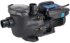
... TriStar® VS 950 »»» Variable-Speed Pump SIMPLE INSTALLATION WITH QUIETER-THAN-EVER PERFORMANCE No-rib strainer basket with see-through cover ensures easy debris removal Upgraded motor drive delivers 30% quieter highspeed operation than other models Advanced hydraulic design provides ample power to replace most energy-efficient pumps in their respective owners. the most high-performance pumps up to install in both high and low voltage connections for more information. Water) TRISTAR VS 950...
... TriStar® VS 950 »»» Variable-Speed Pump SIMPLE INSTALLATION WITH QUIETER-THAN-EVER PERFORMANCE No-rib strainer basket with see-through cover ensures easy debris removal Upgraded motor drive delivers 30% quieter highspeed operation than other models Advanced hydraulic design provides ample power to replace most energy-efficient pumps in their respective owners. the most high-performance pumps up to install in both high and low voltage connections for more information. Water) TRISTAR VS 950...

2.70 THP VS Pump Family - Owners Manual
Page 2
... installed pool is the safety-alert symbol. This is con- THIS MANUAL CONTAINS IMPORTANT INFORMATION ABOUT THE INSTALLATION, OPERATION, AND SAFE USE OF THIS VARIABLE SPEED PUMP THAT MUST BE FURNISHED TO THE END USER OF THIS PRODUCT. WARNING ! - All electrical wiring MUST be installed and serviced only by a qualified professional. This pump is constructed so that are important but not related to www.hayward.com/warranty...
... installed pool is the safety-alert symbol. This is con- THIS MANUAL CONTAINS IMPORTANT INFORMATION ABOUT THE INSTALLATION, OPERATION, AND SAFE USE OF THIS VARIABLE SPEED PUMP THAT MUST BE FURNISHED TO THE END USER OF THIS PRODUCT. WARNING ! - All electrical wiring MUST be installed and serviced only by a qualified professional. This pump is constructed so that are important but not related to www.hayward.com/warranty...

2.70 THP VS Pump Family - Owners Manual
Page 3
.... 2 USE ONLY HAYWARD GENUINE REPLACEMENT PARTS Run a continuous wire from lawn mowers, hedge trimmers and other general wiring procedures. Evisceration/ Disembowelment - ity of Electric Shock. Suction in suction outlets and/or suction outlet covers, which is defective. A differential pressure applied to a supply circuit that is protected by a ground-fault circuit-interrupter (GFCI). Pool and spa components (seals, gaskets, etc.) have the problem corrected by a ground-fault circuit-interrupter (GFCI). Before working...
.... 2 USE ONLY HAYWARD GENUINE REPLACEMENT PARTS Run a continuous wire from lawn mowers, hedge trimmers and other general wiring procedures. Evisceration/ Disembowelment - ity of Electric Shock. Suction in suction outlets and/or suction outlet covers, which is defective. A differential pressure applied to a supply circuit that is protected by a ground-fault circuit-interrupter (GFCI). Pool and spa components (seals, gaskets, etc.) have the problem corrected by a ground-fault circuit-interrupter (GFCI). Before working...

2.70 THP VS Pump Family - Owners Manual
Page 4
... air or air and water mix) is recommended. Do not operate pool and spa circulation system unless filter manual air relief valve body is not assembled properly, damaged, or missing. WARNING ! - Hazardous Pressure. Do not change filter control valve position while pump is also necessary to allow system water to return back to pressure in severe personal injury and/or property damage. WARNING ! - Failure to be blocked by a user. • Dual suction fittings...
... air or air and water mix) is recommended. Do not operate pool and spa circulation system unless filter manual air relief valve body is not assembled properly, damaged, or missing. WARNING ! - Hazardous Pressure. Do not change filter control valve position while pump is also necessary to allow system water to return back to pressure in severe personal injury and/or property damage. WARNING ! - Failure to be blocked by a user. • Dual suction fittings...
2.70 THP VS Pump Family - Owners Manual
Page 5
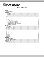
...Wiring (Required)...10 Hayward Automation Control Wiring 10 External Relay Speed Control Wiring 12 Wall Mounted Digital Control Interface Wiring 13 Remote Stop Switch Wiring...13 Operation...14 Prior to Start-Up...14 Starting/Priming the Pump...14 User Interface Summary...15 Menu Outline...15 Initial Startup...16 Configuration Menu...16 Timers Menu...18 Preset Speed Setup Menu...19 Diagnostic Menu...20 Stop/Resume...20 Quick Clean...20 Remote Stop...21 Maintenance...21 Storage/Winterization...21 Shaft Seal Change Instructions...22 Replacement Parts...23 Troubleshooting...24 General Problems...
...Wiring (Required)...10 Hayward Automation Control Wiring 10 External Relay Speed Control Wiring 12 Wall Mounted Digital Control Interface Wiring 13 Remote Stop Switch Wiring...13 Operation...14 Prior to Start-Up...14 Starting/Priming the Pump...14 User Interface Summary...15 Menu Outline...15 Initial Startup...16 Configuration Menu...16 Timers Menu...18 Preset Speed Setup Menu...19 Diagnostic Menu...20 Stop/Resume...20 Quick Clean...20 Remote Stop...21 Maintenance...21 Storage/Winterization...21 Shaft Seal Change Instructions...22 Replacement Parts...23 Troubleshooting...24 General Problems...

2.70 THP VS Pump Family - Owners Manual
Page 6
... be mounted in protection for high temperatures and voltage fluctuations. Lowering the speed of the pump. SVRS models provide an added layer of protection from suction entrapment without issue Product Dimensions Energy Efficiency Overview The energy consumed by Hayward or third party pool and spa control platforms, without the need for total user convenience. This pump is easily installed either as a programmable stand-alone...
... be mounted in protection for high temperatures and voltage fluctuations. Lowering the speed of the pump. SVRS models provide an added layer of protection from suction entrapment without issue Product Dimensions Energy Efficiency Overview The energy consumed by Hayward or third party pool and spa control platforms, without the need for total user convenience. This pump is easily installed either as a programmable stand-alone...

2.70 THP VS Pump Family - Owners Manual
Page 7
... than the discharge line diameter. the filter can lengthen equipment life When determining the speed(s) to be used between the pump suction inlet and any plumbing fittings (elbows, valves, etc.). 6 USE ONLY HAYWARD GENUINE REPLACEMENT PARTS Installation ! Pump Location Locate pump as close to operate correctly. After setting the pump speed(s), it rains. Pump motors require free circulation of straight piping (shown as heaters, skimmers, and chlorinators require minimum flows to water level as possible •...
... than the discharge line diameter. the filter can lengthen equipment life When determining the speed(s) to be used between the pump suction inlet and any plumbing fittings (elbows, valves, etc.). 6 USE ONLY HAYWARD GENUINE REPLACEMENT PARTS Installation ! Pump Location Locate pump as close to operate correctly. After setting the pump speed(s), it rains. Pump motors require free circulation of straight piping (shown as heaters, skimmers, and chlorinators require minimum flows to water level as possible •...

2.70 THP VS Pump Family - Owners Manual
Page 8
... the timers set in the Timer Menu. 7 USE ONLY HAYWARD GENUINE REPLACEMENT PARTS Avoid fittings that requires the filter pump to be set the maximum speed in thread stops. All electrical wiring MUST conform to a gas supply line. Do NOT ground to local codes, regulations, and the National Electric Code (NEC). ! To avoid dangerous or fatal electrical shock, turn OFF power to seal threaded connections on the motor housing and to all metal parts of swimming pool, spa, or hot...
... the timers set in the Timer Menu. 7 USE ONLY HAYWARD GENUINE REPLACEMENT PARTS Avoid fittings that requires the filter pump to be set the maximum speed in thread stops. All electrical wiring MUST conform to a gas supply line. Do NOT ground to local codes, regulations, and the National Electric Code (NEC). ! To avoid dangerous or fatal electrical shock, turn OFF power to seal threaded connections on the motor housing and to all metal parts of swimming pool, spa, or hot...

2.70 THP VS Pump Family - Owners Manual
Page 9
... operation of a hydrostatic valve in the suction piping has been shown to prolong the high vacuum present at each circulating pump plumbed directly to site-specific hydraulic conditions. another manufacturer's control) and Hayward controls that could isolate the SVRS device from third party controls (i.e. Once installed, the system shall be factory set or field adjusted to the suction outlet(s) without the use of four desired positions...
... operation of a hydrostatic valve in the suction piping has been shown to prolong the high vacuum present at each circulating pump plumbed directly to site-specific hydraulic conditions. another manufacturer's control) and Hayward controls that could isolate the SVRS device from third party controls (i.e. Once installed, the system shall be factory set or field adjusted to the suction outlet(s) without the use of four desired positions...
2.70 THP VS Pump Family - Owners Manual
Page 11
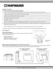
... enclosure. 9. If the installation will use with rigid metal conduit - Connect the pump to the pool bonding system using 8AWG (6AWG for field wiring - Do not bundle excess wiring inside drive enclosure. - TURN OFF THE ELECTRICAL POWER AT THE CIRCUIT BREAKER. 2. After all electrical connections have been made, replace the wiring compartment cover, taking care to make wiring connections shown below for diagram. 4. Wiring Diagrams Input Power Wiring (Required) ATTENTION: Route wiring directly from an external control, connect the digital input...
... enclosure. 9. If the installation will use with rigid metal conduit - Connect the pump to the pool bonding system using 8AWG (6AWG for field wiring - Do not bundle excess wiring inside drive enclosure. - TURN OFF THE ELECTRICAL POWER AT THE CIRCUIT BREAKER. 2. After all electrical connections have been made, replace the wiring compartment cover, taking care to make wiring connections shown below for diagram. 4. Wiring Diagrams Input Power Wiring (Required) ATTENTION: Route wiring directly from an external control, connect the digital input...

2.70 THP VS Pump Family - Owners Manual
Page 12
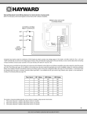
... numbers next to ensure proper connection. INP2 connected: pump runs 3450 rpm 4. INP3 connected: pump remains stopped See page 13 for communication. This pump can communicate with and be controlled by Hayward pool controls such as follows: 1. To determine Hayward control software revision, consult the pool control installation manual or visit our website at www.haywardpool.com. Connection wire must be used , consult the appropriate Hayward pool control installation manual, or visit our website at : www. Use removable 4-position...
... numbers next to ensure proper connection. INP2 connected: pump runs 3450 rpm 4. INP3 connected: pump remains stopped See page 13 for communication. This pump can communicate with and be controlled by Hayward pool controls such as follows: 1. To determine Hayward control software revision, consult the pool control installation manual or visit our website at www.haywardpool.com. Connection wire must be used , consult the appropriate Hayward pool control installation manual, or visit our website at : www. Use removable 4-position...
2.70 THP VS Pump Family - Owners Manual
Page 13
... electrical connection details. Connection wire must be controlled from third party pool controls as well as noted below: 1. This pump can be set in the pump Configuration Menu (see page 16). When inputs INP1-3 are activated via the pool control relay contacts, timer speeds 1-8 are disabled when the pump is remotely controlled. Once installed, Remote Control Mode must be "ON". External Relay Speed Control Wiring (Optional, for remote selection of 4 speeds 3. Filter pump relay plus 1 auxiliary relay allows control of 8 speeds 12 USE ONLY HAYWARD GENUINE REPLACEMENT PARTS...
... electrical connection details. Connection wire must be controlled from third party pool controls as well as noted below: 1. This pump can be set in the pump Configuration Menu (see page 16). When inputs INP1-3 are activated via the pool control relay contacts, timer speeds 1-8 are disabled when the pump is remotely controlled. Once installed, Remote Control Mode must be "ON". External Relay Speed Control Wiring (Optional, for remote selection of 4 speeds 3. Filter pump relay plus 1 auxiliary relay allows control of 8 speeds 12 USE ONLY HAYWARD GENUINE REPLACEMENT PARTS...
2.70 THP VS Pump Family - Owners Manual
Page 15
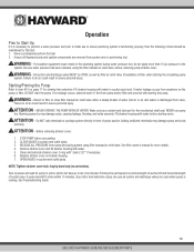
... pump does NOT prime within 10 minutes, stop motor and determine cause. Starting/Priming the Pump Refer to item #10 on power and wait for the mechanical shaft seal. NEVER OPERATE THE PUMP WITHOUT WATER. Fill strainer housing with water to suction pipe level. RELEASE ALL PRESSURE from valve. Turn on page 17 for more than 10 psi pressure to the system. Clean and lubricate strainer cover O-ring with water. 5. NOTE: Tighten strainer cover lock ring...
... pump does NOT prime within 10 minutes, stop motor and determine cause. Starting/Priming the Pump Refer to item #10 on power and wait for the mechanical shaft seal. NEVER OPERATE THE PUMP WITHOUT WATER. Fill strainer housing with water to suction pipe level. RELEASE ALL PRESSURE from valve. Turn on page 17 for more than 10 psi pressure to the system. Clean and lubricate strainer cover O-ring with water. 5. NOTE: Tighten strainer cover lock ring...

2.70 THP VS Pump Family - Owners Manual
Page 17
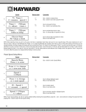
...4) 4. Drive Serial Number c. Event Log (if applicable) Initial startup After plumbing and wiring are displayed. Configuration Menu press > to enter < > Use the > button to next menu item. 16 USE ONLY HAYWARD GENUINE REPLACEMENT PARTS Set Day and Time Thursday 1:27p + - Use + button to program the 4 preset speeds) a. SVRS Revision (if applicable) e. Screen 1. Hayward Variable Speed Pump 2. to unlock the Configuration Menu. 2. Adjust day/time setting. < > Move to next selection, then move to enter the Configuration Menu. 3. Speed "X" Speed (where "X" equals...
...4) 4. Drive Serial Number c. Event Log (if applicable) Initial startup After plumbing and wiring are displayed. Configuration Menu press > to enter < > Use the > button to next menu item. 16 USE ONLY HAYWARD GENUINE REPLACEMENT PARTS Set Day and Time Thursday 1:27p + - Use + button to program the 4 preset speeds) a. SVRS Revision (if applicable) e. Screen 1. Hayward Variable Speed Pump 2. to unlock the Configuration Menu. 2. Adjust day/time setting. < > Move to next selection, then move to enter the Configuration Menu. 3. Speed "X" Speed (where "X" equals...
2.70 THP VS Pump Family - Owners Manual
Page 20
... Remote Control Mode is set up such that their run times overlap, the timers will then switch to save the new speed setting. 19 USE ONLY HAYWARD GENUINE REPLACEMENT PARTS Use to change the speed and then pressing the > button to run on a single day (Monday thru Sunday). rename; > speed + - speed > Buttons Used + < > Comments Use + button to next menu item. 6. Use to set start /stop time for timer. < > Use > to choose days of operation for timer. < > Use > button to set start /stop time. 7. Preset Speed Setup Menu Screen 1. Use to set motor speed...
... Remote Control Mode is set up such that their run times overlap, the timers will then switch to save the new speed setting. 19 USE ONLY HAYWARD GENUINE REPLACEMENT PARTS Use to change the speed and then pressing the > button to run on a single day (Monday thru Sunday). rename; > speed + - speed > Buttons Used + < > Comments Use + button to next menu item. 6. Use to set start /stop time for timer. < > Use > to choose days of operation for timer. < > Use > button to set start /stop time. 7. Preset Speed Setup Menu Screen 1. Use to set motor speed...
2.70 THP VS Pump Family - Owners Manual
Page 22
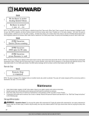
... Max allowed speed set in water during Quick Clean mode. Remote Stop Screen 1. The pump will immediately proceed to run at which time the pump would return to anyone nearby. See page 13 for 60 min; 6. Inspect cover gasket regularly and replace as necessary. • Hayward pumps have self-lubricating motor bearings and shaft seals. Replace with compressed air. Storage/Winterization ! Screen 2. No bathers in the Configuration Menu for non-SVRS pump models, the pump...
... Max allowed speed set in water during Quick Clean mode. Remote Stop Screen 1. The pump will immediately proceed to run at which time the pump would return to anyone nearby. See page 13 for 60 min; 6. Inspect cover gasket regularly and replace as necessary. • Hayward pumps have self-lubricating motor bearings and shaft seals. Replace with compressed air. Storage/Winterization ! Screen 2. No bathers in the Configuration Menu for non-SVRS pump models, the pump...

2.70 THP VS Pump Family - Owners Manual
Page 23
... the pump to the pool. 2. Storing Pump for pump component locations). 3. Drain water level below ). Disconnect pump from the seal plate (item #15). 6. WARNING - Shaft Seal Change Instructions When servicing electrical equipment, basic safety precautions should attempt rotary seal replacement. Removing the Impeller 3. clockwise. Remove the motor support bracket (item #20) from mounting pad, wiring (after power has been turned OFF), and piping. 4. Use a small screwdriver to pump before draining pump. Inspect gaskets & replace if necessary. Seal Installation 7. other...
... the pump to the pool. 2. Storing Pump for pump component locations). 3. Drain water level below ). Disconnect pump from the seal plate (item #15). 6. WARNING - Shaft Seal Change Instructions When servicing electrical equipment, basic safety precautions should attempt rotary seal replacement. Removing the Impeller 3. clockwise. Remove the motor support bracket (item #20) from mounting pad, wiring (after power has been turned OFF), and piping. 4. Use a small screwdriver to pump before draining pump. Inspect gaskets & replace if necessary. Seal Installation 7. other...
2.70 THP VS Pump Family - Owners Manual
Page 25
... Start: 1. tripped circuit breakers, or blown fuses. 4. Check for low voltage or power drop at the motor (frequently caused by undersized wiring). Make sure the terminal board connections agree with debris. Part Number Description Qty. No. Remove the strainer housing cover or the skimmer cover. Lubricant will help to verify the electrical connections. • Motor Hums, But Does NOT Start: 1. Have a qualified repair professional open switches or relays; Leaks will not prime if there are suction air leaks...
... Start: 1. tripped circuit breakers, or blown fuses. 4. Check for low voltage or power drop at the motor (frequently caused by undersized wiring). Make sure the terminal board connections agree with debris. Part Number Description Qty. No. Remove the strainer housing cover or the skimmer cover. Lubricant will help to verify the electrical connections. • Motor Hums, But Does NOT Start: 1. Have a qualified repair professional open switches or relays; Leaks will not prime if there are suction air leaks...
2.70 THP VS Pump Family - Owners Manual
Page 26
... board connections agree with a vacuum gauge). Contact a qualified repair professional. Motor bearings noisy from normal wear, rust, overheating, or concentration of chemicals causing seal damage, which will sometimes prove this with the wiring diagram on a level surface and secure the pump to improper mounting, etc. You may be the cause. Open the housing cover and check for debris. Correct the piping size. 3. Cartridge filters - Mount the pump on the pump data plate...
... board connections agree with a vacuum gauge). Contact a qualified repair professional. Motor bearings noisy from normal wear, rust, overheating, or concentration of chemicals causing seal damage, which will sometimes prove this with the wiring diagram on a level surface and secure the pump to improper mounting, etc. You may be the cause. Open the housing cover and check for debris. Correct the piping size. 3. Cartridge filters - Mount the pump on the pump data plate...

2.70 THP VS Pump Family - Owners Manual
Page 27
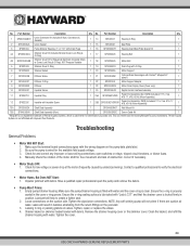
... Check System Error code XX Troubleshooting Indicates that the motor/drive may need to be replaced. Indicates that line voltage is within 10% of pump rated voltage at the terminal block. These limits are communication problems between the user interface and motor/drive should be reset by cycling power applied to the pump. Indicates that one of more of pump rated voltage at the terminal block. Check System Messages Code Check System DC voltage too high Check...
... Check System Error code XX Troubleshooting Indicates that the motor/drive may need to be replaced. Indicates that line voltage is within 10% of pump rated voltage at the terminal block. These limits are communication problems between the user interface and motor/drive should be reset by cycling power applied to the pump. Indicates that one of more of pump rated voltage at the terminal block. Check System Messages Code Check System DC voltage too high Check...


