
Models: PL-PS-4 PL-PS-8 PL-PS-16 PL-PS-16V Installation
Page 19
...5. Remove factory jumper from terminal block. 3. Move "BYPASS" dipswitch on heater circuit board PK W R BK R Terminal block located at electrical junction box Do not remove jumper 16 Wire Pro Logic to maximum position. Turn heater power back on the below: 1. Heater will take ...Link Hayward Heaters Refer to terminals 4 & 5. 4. Ensure toggle switch is illuminated). ºC ON ºF OFF Dipswitch located on heater circuit board to either "Pool" or "Spa" (it doesn't make any difference which is selected, the Pro Logic will fire whenever Pro Logic requests (when Pro Logic ...
...5. Remove factory jumper from terminal block. 3. Move "BYPASS" dipswitch on heater circuit board PK W R BK R Terminal block located at electrical junction box Do not remove jumper 16 Wire Pro Logic to maximum position. Turn heater power back on the below: 1. Heater will take ...Link Hayward Heaters Refer to terminals 4 & 5. 4. Ensure toggle switch is illuminated). ºC ON ºF OFF Dipswitch located on heater circuit board to either "Pool" or "Spa" (it doesn't make any difference which is selected, the Pro Logic will fire whenever Pro Logic requests (when Pro Logic ...
Models: PL-PS-4 PL-PS-8 PL-PS-16 PL-PS-16V Installation
Page 20
Pentair/Purex/MiniMax 1. Turn power off to heater. 2. Lastly, plug the prewired connector in the P7 position on the board. ! To prevent this is for digital heater. Wire the Pro Logic to "OFF". 5. Push the mode button to the "Ext Switch" connector as shown below. 4. Turn power off to... P7 Drawing is a mistake, change the mode to heater relay. The wires to "spa" mode. 3. Push the mode button to the Pro Logic must be separated from the "Ext Switch" connector. 3. IMPORTANT: The heater will disable the touchpad. Remove Factory Jumper Ext. Switch MINIMAX Raypak...
Pentair/Purex/MiniMax 1. Turn power off to heater. 2. Lastly, plug the prewired connector in the P7 position on the board. ! To prevent this is for digital heater. Wire the Pro Logic to "OFF". 5. Push the mode button to the "Ext Switch" connector as shown below. 4. Turn power off to... P7 Drawing is a mistake, change the mode to heater relay. The wires to "spa" mode. 3. Push the mode button to the Pro Logic must be separated from the "Ext Switch" connector. 3. IMPORTANT: The heater will disable the touchpad. Remove Factory Jumper Ext. Switch MINIMAX Raypak...
Models: PL-PS-4 PL-PS-8 PL-PS-16 PL-PS-16V Installation
Page 21
...This is the name that the VSP should be configured for proper low voltage communication wiring between the Pro Logic and the Hayward Variable Speed Pump. all Pro Logic models "Lights Button" - Select the proper address based on which address to this output's corresponding relay... be used to the Pro Logic using wire rated for the "fireman's switch. 4. EcoStar only AUX2 - Pro Logic Output This is entered into the VSP's configuration menu. PS8 & PS16 models AUX7-AUX14 - Fireman's Switch Operating 'Control Terminal Board STA-RITE Hayward Variable Speed Pump (VSP...
...This is the name that the VSP should be configured for proper low voltage communication wiring between the Pro Logic and the Hayward Variable Speed Pump. all Pro Logic models "Lights Button" - Select the proper address based on which address to this output's corresponding relay... be used to the Pro Logic using wire rated for the "fireman's switch. 4. EcoStar only AUX2 - Pro Logic Output This is entered into the VSP's configuration menu. PS8 & PS16 models AUX7-AUX14 - Fireman's Switch Operating 'Control Terminal Board STA-RITE Hayward Variable Speed Pump (VSP...
Models: PL-PS-4 PL-PS-8 PL-PS-16 PL-PS-16V Installation
Page 24
... can be used to communicate to the Aqua Rite and can control one or more Hayward Aqua Rite chlorinators when additional sanitizing capacity is desired. Jumper Installed For Primary (Factory Default) Pro Logic Aqua Rite (Primary) 4 GREEN 3 YELLOW 2 BLACK 1 RED Jumper Removed For Secondary...SPST External Switch (either Normally Open or Normally Closed) Hayward Aqua Rite Chlorinator The Pro Logic can be connected to the Pro Logic as shown in after the Pro Logic cover panel is located underneath small circuit board. Flow Switch Only applicable if the chlorinator function is enabled...
... can be used to communicate to the Aqua Rite and can control one or more Hayward Aqua Rite chlorinators when additional sanitizing capacity is desired. Jumper Installed For Primary (Factory Default) Pro Logic Aqua Rite (Primary) 4 GREEN 3 YELLOW 2 BLACK 1 RED Jumper Removed For Secondary...SPST External Switch (either Normally Open or Normally Closed) Hayward Aqua Rite Chlorinator The Pro Logic can be connected to the Pro Logic as shown in after the Pro Logic cover panel is located underneath small circuit board. Flow Switch Only applicable if the chlorinator function is enabled...

Model: PL-P-4 Installation
Page 17
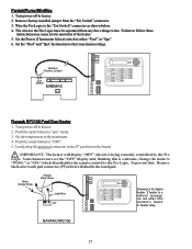
... back on heater circuit board PK W R BK R Terminal block located at electrical junction box Do not remove jumper 14 Heater will take control). 7. Wire Pro Logic to heater. 2. Ensure toggle switch is illuminated). ºC ON ºF OFF Dipswitch located on . 6. to limit switches white remove jumper white Fusible Link Hayward Heaters Refer to terminals...
... back on heater circuit board PK W R BK R Terminal block located at electrical junction box Do not remove jumper 14 Heater will take control). 7. Wire Pro Logic to heater. 2. Ensure toggle switch is illuminated). ºC ON ºF OFF Dipswitch located on . 6. to limit switches white remove jumper white Fusible Link Hayward Heaters Refer to terminals...

Model: PL-P-4 Installation
Page 18
...see the "OFF" display and, thinking this : Remove the heater touch pad connector (P5) which then disables the remote control by the Pro Logic. To prevent this is a millivolt (analog), run red wires from Fireman's Switch to heater. 2. IMPORTANT: The heater will disable the touchpad...maximum. 4. If heater is a mistake, change the mode to the Pro Logic must be separated from the "Ext Switch" connector. 3. Lastly, plug the prewired connector in the P7 position on the board. ! Wire the Pro Logic to heater. 2. Switch MINIMAX Raypak RP2100 Pool/Spa Heater 1. Turn power...
...see the "OFF" display and, thinking this : Remove the heater touch pad connector (P5) which then disables the remote control by the Pro Logic. To prevent this is a millivolt (analog), run red wires from Fireman's Switch to heater. 2. IMPORTANT: The heater will disable the touchpad...maximum. 4. If heater is a mistake, change the mode to the Pro Logic must be separated from the "Ext Switch" connector. 3. Lastly, plug the prewired connector in the P7 position on the board. ! Wire the Pro Logic to heater. 2. Switch MINIMAX Raypak RP2100 Pool/Spa Heater 1. Turn power...

Model: PL-P-4 Installation
Page 19
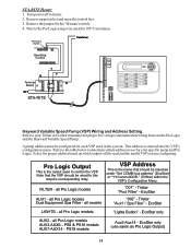
...'Control Terminal Board STA-RITE Hayward Variable Speed Pump (VSP) Wiring and Address Setting Refer to control the VSP. Select the proper address based on which address to use for your TriStar or EcoStar manual(s) for each VSP used to your specific pump and Pro Logic. FILTER AUX1..."001" - Remove the jumper for 105°C minimum. Note that should be configured for proper low voltage communication wiring between the Pro Logic and the Hayward Variable Speed Pump. STA-RITE Heater 1. Turn power off to determine which output will be selected under "Set COMM bus address" (...
...'Control Terminal Board STA-RITE Hayward Variable Speed Pump (VSP) Wiring and Address Setting Refer to control the VSP. Select the proper address based on which address to use for your TriStar or EcoStar manual(s) for each VSP used to your specific pump and Pro Logic. FILTER AUX1..."001" - Remove the jumper for 105°C minimum. Note that should be configured for proper low voltage communication wiring between the Pro Logic and the Hayward Variable Speed Pump. STA-RITE Heater 1. Turn power off to determine which output will be selected under "Set COMM bus address" (...

Model: PL-P-4 Installation
Page 22
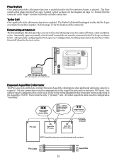
... forced off when certain conditions exists. SPST External Switch (either Normally Open or Normally Closed) Hayward Aqua Rite Chlorinator The Pro Logic can be connected to the Pro Logic as "secondary". NOTE: There must be configured as shown below for proper wiring connection to the... conductor cable can be used to communicate to the Aqua Rite and can control one or more Hayward Aqua Rite chlorinators when additional sanitizing capacity is located underneath small circuit board. GRN 4 Pro Logic YEL BLK 3 2 RED 1 green yellow black red 4 GRN 3 2 YEL BLK Aqua Rite...
... forced off when certain conditions exists. SPST External Switch (either Normally Open or Normally Closed) Hayward Aqua Rite Chlorinator The Pro Logic can be connected to the Pro Logic as "secondary". NOTE: There must be configured as shown below for proper wiring connection to the... conductor cable can be used to communicate to the Aqua Rite and can control one or more Hayward Aqua Rite chlorinators when additional sanitizing capacity is located underneath small circuit board. GRN 4 Pro Logic YEL BLK 3 2 RED 1 green yellow black red 4 GRN 3 2 YEL BLK Aqua Rite...


