
All Max-Flo II models
Page 1
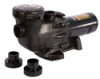
... SERIOUS INJURY. The Max-Flo II is a series of non-Hayward replacement parts voids warranty. ATTENTION INSTALLER - THIS MANUAL CONTAINS IMPORTANT INFORMATION ABOUT THE INSTALLATION, OPERATION, AND SAFE USE OF THIS PUMP THAT MUST BE FURNISHED TO THE END USER OF THIS PRODUCT. The Hayward Max-Flo II™ is an... ideal choice for improved motor cooling and to avoid unnecessary service calls, read this manual. P/N: IS2700 REV. Designed for pools ...
... SERIOUS INJURY. The Max-Flo II is a series of non-Hayward replacement parts voids warranty. ATTENTION INSTALLER - THIS MANUAL CONTAINS IMPORTANT INFORMATION ABOUT THE INSTALLATION, OPERATION, AND SAFE USE OF THIS PUMP THAT MUST BE FURNISHED TO THE END USER OF THIS PRODUCT. The Hayward Max-Flo II™ is an... ideal choice for improved motor cooling and to avoid unnecessary service calls, read this manual. P/N: IS2700 REV. Designed for pools ...
All Max-Flo II models
Page 2
...if found to prevent overheating of the motor. Do NOT use or climb on permanently installed swimming pools and may result in this manual, look for one that are important but not related to the potential for use , it cannot be installed and serviced only by... Code (NEC). ATTENTION INSTALLER - Max-Flo II ™ Series ____ ____ _____ _ Page 2 of 16 IMPORTANT SAFETY INSTRUCTIONS Before installing or servicing this product. FAILURE TO READ AND FOLLOW ALL INSTRUCTIONS COULD RESULT IN SERIOUS INJURY. This pump is capable of non-Hayward replacement parts voids warranty. Select a...
...if found to prevent overheating of the motor. Do NOT use or climb on permanently installed swimming pools and may result in this manual, look for one that are important but not related to the potential for use , it cannot be installed and serviced only by... Code (NEC). ATTENTION INSTALLER - Max-Flo II ™ Series ____ ____ _____ _ Page 2 of 16 IMPORTANT SAFETY INSTRUCTIONS Before installing or servicing this product. FAILURE TO READ AND FOLLOW ALL INSTRUCTIONS COULD RESULT IN SERIOUS INJURY. This pump is capable of non-Hayward replacement parts voids warranty. Select a...

All Max-Flo II models
Page 3
...and/or death due to the following entrapment hazards: Hair Entrapment- www.haywardpool.com USE ONLY HAYWARD GENUINE REPLACEMENT PARTS Before working on how to all electrical equipment, metal piping (except gas piping...evisceration/disembowelment. In addition to two or more suction outlets per pump must be placed in suction outlet cover. Max-Flo II™ Series _____ _____ _____ _____ Page 3 of swimming pool,...rod or mesh. Run a continuous wire from near point to the pump. WARNING - To Reduce the risk of this manual. - floor or wall), must be located on seating areas or...
...and/or death due to the following entrapment hazards: Hair Entrapment- www.haywardpool.com USE ONLY HAYWARD GENUINE REPLACEMENT PARTS Before working on how to all electrical equipment, metal piping (except gas piping...evisceration/disembowelment. In addition to two or more suction outlets per pump must be placed in suction outlet cover. Max-Flo II™ Series _____ _____ _____ _____ Page 3 of swimming pool,...rod or mesh. Run a continuous wire from near point to the pump. WARNING - To Reduce the risk of this manual. - floor or wall), must be located on seating areas or...

All Max-Flo II models
Page 4
...to all internal components by just removing 4 bolts. Before servicing pool and spa circulation system, all system and pump controls must be in open position. Max-Flo II™ Pump Series __________ _____ Page 4 of water (not air or air and water) is discharged. Never operate or...void warranty. Do not close filter manual air relief valve until a steady stream of 16 WARNING - Separation Hazard. WARNING - It is also necessary to allow system water to return back to pressure in violent separation of the Hayward Max-Flo IITM Series. The instructions in ...
...to all internal components by just removing 4 bolts. Before servicing pool and spa circulation system, all system and pump controls must be in open position. Max-Flo II™ Pump Series __________ _____ Page 4 of water (not air or air and water) is discharged. Never operate or...void warranty. Do not close filter manual air relief valve until a steady stream of 16 WARNING - Separation Hazard. WARNING - It is also necessary to allow system water to return back to pressure in violent separation of the Hayward Max-Flo IITM Series. The instructions in ...

All Max-Flo II models
Page 7
... test, prior to initial use size and type wire required by fully opening filter manual air relief valve until a steady stream of water (not air or air and ...pump system. Ensure all applicable local codes, regulations, and the National Electric Code (NEC). Run pressure test for this test. 2. Failure to do so could potentially cause electrical shock if grounded or shorted. Max-Flo II... local or national electrical code requirements. www.haywardpool.com USE ONLY HAYWARD GENUINE REPLACEMENT PARTS WARNING - Pump MUST be more than 24 hours. Start-Up & Operation Prior ...
... test, prior to initial use size and type wire required by fully opening filter manual air relief valve until a steady stream of water (not air or air and ...pump system. Ensure all applicable local codes, regulations, and the National Electric Code (NEC). Run pressure test for this test. 2. Failure to do so could potentially cause electrical shock if grounded or shorted. Max-Flo II... local or national electrical code requirements. www.haywardpool.com USE ONLY HAYWARD GENUINE REPLACEMENT PARTS WARNING - Pump MUST be more than 24 hours. Start-Up & Operation Prior ...

All Max-Flo II models
Page 8
...self-priming using 1 ½" pipe. Drain all pressure from filter, pump, and piping system. Max-Flo II ™ Series Page 8 of 16 Starting/Priming the Pump Release all water from pump and piping when expecting freezing temperatures or when storing pump for a long time (see instructions below 5 PSI), high volume ...to filter to close the manual air relief valve when a steady stream of suction pipe. If water source is discharged from obstruction to do so could result in the system. ATTENTION- Clean and lubricate strainer cover O-ring with genuine Hayward seal assembly kit. Replace ...
...self-priming using 1 ½" pipe. Drain all pressure from filter, pump, and piping system. Max-Flo II ™ Series Page 8 of 16 Starting/Priming the Pump Release all water from pump and piping when expecting freezing temperatures or when storing pump for a long time (see instructions below 5 PSI), high volume ...to filter to close the manual air relief valve when a steady stream of suction pipe. If water source is discharged from obstruction to do so could result in the system. ATTENTION- Clean and lubricate strainer cover O-ring with genuine Hayward seal assembly kit. Replace ...

All Max-Flo II models
Page 9
...and drain plugs. www.haywardpool.com USE ONLY HAYWARD GENUINE REPLACEMENT PARTS Removing the Impeller (See Parts Diagram on the motor shaft). 5. To prevent motor shaft from the motor. 4. Max-Flo II ™ Series Page 9 of the pump/strainer housing (item #4), exposing the diffuser(item... to the pool. 2. Press the ceramic seat with the polished side of this manual for pump component locations.) 6. Seal Installation (See Parts Diagram on page 11 of this manual for pump component locations.) 1. Clean all inlets to follow instructions may result in a dry area...
...and drain plugs. www.haywardpool.com USE ONLY HAYWARD GENUINE REPLACEMENT PARTS Removing the Impeller (See Parts Diagram on the motor shaft). 5. To prevent motor shaft from the motor. 4. Max-Flo II ™ Series Page 9 of the pump/strainer housing (item #4), exposing the diffuser(item... to the pool. 2. Press the ceramic seat with the polished side of this manual for pump component locations.) 6. Seal Installation (See Parts Diagram on page 11 of this manual for pump component locations.) 1. Clean all inlets to follow instructions may result in a dry area...

All Max-Flo II models
Page 10
...HAYWARD GENUINE REPLACEMENT PARTS Screw the impeller (item#10) onto the motor shaft in the seal plate (item#13). Replace two diffuser screws (item #7). Place the diffuser (item #9) over the impeller (item#10) onto the seal plate (item#13), aligning the three (3) protruding pins with a clean, soft, cotton cloth. 11. Max-Flo II... ™ Series Page 10 of this page. Note: Arrow on page 11 of this manual for pump component locations.) 11. Replacing the Impeller and Diffuser (See Parts Diagram ...
...HAYWARD GENUINE REPLACEMENT PARTS Screw the impeller (item#10) onto the motor shaft in the seal plate (item#13). Replace two diffuser screws (item #7). Place the diffuser (item #9) over the impeller (item#10) onto the seal plate (item#13), aligning the three (3) protruding pins with a clean, soft, cotton cloth. 11. Max-Flo II... ™ Series Page 10 of this page. Note: Arrow on page 11 of this manual for pump component locations.) 11. Replacing the Impeller and Diffuser (See Parts Diagram ...

All Max-Flo II models
Page 13
...causing windings to Steps 4 & 5 of vacuum at full RPM's. NOTE - www.haywardpool.com USE ONLY HAYWARD GENUINE REPLACEMENT PARTS Be sure motor is felt, check for clogging or obstruction in bubbles emanating from return fittings...manual. 3. The motor will result in suction. Low Flow - Motor Shuts OFF - You should have a timer, be able to create a tighter seal. 2. Max-Flo II ™ Series Page 13 of overheating. If you have 5"-6" of "Shaft Seal Change Instructions" in the cover o-ring groove. Leaks will automatically shut off to determine if pump...
...causing windings to Steps 4 & 5 of vacuum at full RPM's. NOTE - www.haywardpool.com USE ONLY HAYWARD GENUINE REPLACEMENT PARTS Be sure motor is felt, check for clogging or obstruction in bubbles emanating from return fittings...manual. 3. The motor will result in suction. Low Flow - Motor Shuts OFF - You should have a timer, be able to create a tighter seal. 2. Max-Flo II ™ Series Page 13 of overheating. If you have 5"-6" of "Shaft Seal Change Instructions" in the cover o-ring groove. Leaks will automatically shut off to determine if pump...


