Universal H Series Troubleshooting Guide
Page 3
...-33 5. "EE" or "CE" Code 36-37 Troubleshooting (cont.): 7. "IO" or "SB" Code 8. "HF" Code 44-45 11. "AO" Code 58-60 Heat Exchanger: Flow requirements 61 Heat Exchanger: Inspection 62 Heat Exchanger: Potential Failure Causes 63 UHS Wiring Schematic 64 UHS Wiring Diagram 65 3 "SF" or "HS" Code 9. Open FC3&/F1 Fuse 29-31 4. "PF...
...-33 5. "EE" or "CE" Code 36-37 Troubleshooting (cont.): 7. "IO" or "SB" Code 8. "HF" Code 44-45 11. "AO" Code 58-60 Heat Exchanger: Flow requirements 61 Heat Exchanger: Inspection 62 Heat Exchanger: Potential Failure Causes 63 UHS Wiring Schematic 64 UHS Wiring Diagram 65 3 "SF" or "HS" Code 9. Open FC3&/F1 Fuse 29-31 4. "PF...
Universal H Series Troubleshooting Guide
Page 51
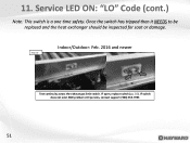
11. Indoor/Outdoor: Feb. 2016 and newer Step 11I Test continuity across the exhaust gas limit switch. Once the switch has tripped then it NEEDS to be replaced and the heat exchanger should be inspected for soot or damage. IF open, replace switch (pg. 20). Service LED ON: "LO" Code (cont.) Note: This switch is a one time safety. IF switch does not exist AND problem still persists, contact support: (908) 355-7995 51
11. Indoor/Outdoor: Feb. 2016 and newer Step 11I Test continuity across the exhaust gas limit switch. Once the switch has tripped then it NEEDS to be replaced and the heat exchanger should be inspected for soot or damage. IF open, replace switch (pg. 20). Service LED ON: "LO" Code (cont.) Note: This switch is a one time safety. IF switch does not exist AND problem still persists, contact support: (908) 355-7995 51

Universal H Series Troubleshooting Guide
Page 61
... issues such as the heater dry firing or water to boil causing high limits to trip and possible damage to heat exchanger. • Flow exceeding maximum flow could cause issues such as it could be checked to the heat exchanger by -pass should be the cause of low or high water flow through the... exchanger Model Min GPM H150FD H200FD 20 H250FD H300FD 25 H350FD H400FD 30 H400FD 40 Maximum water flow 125 GPM 61 ...
... issues such as the heater dry firing or water to boil causing high limits to trip and possible damage to heat exchanger. • Flow exceeding maximum flow could cause issues such as it could be checked to the heat exchanger by -pass should be the cause of low or high water flow through the... exchanger Model Min GPM H150FD H200FD 20 H250FD H300FD 25 H350FD H400FD 30 H400FD 40 Maximum water flow 125 GPM 61 ...

Universal H Series Troubleshooting Guide
Page 62
... there is any doubt as the Model & Serial number decal, and send to whether or not there is damage from plumbing (water connections, 1 inlet, 1 outlet.) 4. Heat Exchanger tubes should look like this picture 62 Remove water connection side Upper End Cap (Black Polymer- 4 screws in rectangle holes marked with an arrow) 3. Disconnect...
... there is any doubt as the Model & Serial number decal, and send to whether or not there is damage from plumbing (water connections, 1 inlet, 1 outlet.) 4. Heat Exchanger tubes should look like this picture 62 Remove water connection side Upper End Cap (Black Polymer- 4 screws in rectangle holes marked with an arrow) 3. Disconnect...

UHS Heater - How To Guide
Page 5
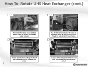
Step 1 Step 2 Remove the black side trim panel (4 screws). How To: Rotate UHS Heat Exchanger Remember, the header does not need to be reversed once the procedure is completed. Step 3 Remove the upper end caps on the header will be removed from the exchanger. Step 4 Remove the flu cover screws (10 screws). 5 Remove the screws as shown (6 screws) and remove the flue cover jacket. Also, the inlet and outlet on both sides of the heater (4 screws, look for the triangles showing the screw location).
Step 1 Step 2 Remove the black side trim panel (4 screws). How To: Rotate UHS Heat Exchanger Remember, the header does not need to be reversed once the procedure is completed. Step 3 Remove the upper end caps on the header will be removed from the exchanger. Step 4 Remove the flu cover screws (10 screws). 5 Remove the screws as shown (6 screws) and remove the flue cover jacket. Also, the inlet and outlet on both sides of the heater (4 screws, look for the triangles showing the screw location).

UHS Heater - How To Guide
Page 6
Step 8 Remove the front access panel (1 retaining screw). 6 Disconnect the RED wire from the pressure switch and the VIOLET wire from the top high limit switch. How To: Rotate UHS Heat Exchanger (cont.) Step 5 Step 6 Remove the rain guard (8 screws as shown). Step 7 Remove the flue collector side panels (3 screws each) Be careful to not damage the insulation. Pull wires back through hole.
Step 8 Remove the front access panel (1 retaining screw). 6 Disconnect the RED wire from the pressure switch and the VIOLET wire from the top high limit switch. How To: Rotate UHS Heat Exchanger (cont.) Step 5 Step 6 Remove the rain guard (8 screws as shown). Step 7 Remove the flue collector side panels (3 screws each) Be careful to not damage the insulation. Pull wires back through hole.
UHS Heater - How To Guide
Page 7
Step 12 Lift and rotate the heat exchanger to the left side of the heater to not damage the insulation as shown. How To: Rotate UHS Heat Exchanger (cont.) Step 9 Step 10 Remove the Thermistor connection from ignition board. Route the RED and VIOLET wires through the hole on the left side as shown (do not flip exchanger, flat rotate). 7 Be careful to the header. Step 11 Pull the Thermistor wire out of heater. Cut the wire tie inside the heater as you lower the exchanger back into the heater cabinet.
Step 12 Lift and rotate the heat exchanger to the left side of the heater to not damage the insulation as shown. How To: Rotate UHS Heat Exchanger (cont.) Step 9 Step 10 Remove the Thermistor connection from ignition board. Route the RED and VIOLET wires through the hole on the left side as shown (do not flip exchanger, flat rotate). 7 Be careful to the header. Step 11 Pull the Thermistor wire out of heater. Cut the wire tie inside the heater as you lower the exchanger back into the heater cabinet.

UHS Heater - How To Guide
Page 8
How To: Rotate UHS Heat Exchanger (cont.) Step 13 Step 14 Route the Thermistor lead back into the cabinet. Check all wires to the ignition board. Step 16 Reattach the Thermistor to make sure there are no loose connections. 8 Reattach all the panels in the reverse order they were removed. Be careful to the pressure and high limit switch. Step 15 Reattach the RED and VIOLET wires to not pinch any wires during reinstallation.
How To: Rotate UHS Heat Exchanger (cont.) Step 13 Step 14 Route the Thermistor lead back into the cabinet. Check all wires to the ignition board. Step 16 Reattach the Thermistor to make sure there are no loose connections. 8 Reattach all the panels in the reverse order they were removed. Be careful to the pressure and high limit switch. Step 15 Reattach the RED and VIOLET wires to not pinch any wires during reinstallation.

UHS Heater - How To Guide
Page 9
Disconnect Unions from plumbing (water connections, 1 inlet, 1 outlet). 9 How To: Heat Exchanger Inspection Step 1 Step 2 Remove the black metal trim plate (around the water manifold, 5 Black screws). Step 3 Remove water connection side Upper End Cap (Black Polymer- 4 screws in rectangle holes marked with an arrow).
Disconnect Unions from plumbing (water connections, 1 inlet, 1 outlet). 9 How To: Heat Exchanger Inspection Step 1 Step 2 Remove the black metal trim plate (around the water manifold, 5 Black screws). Step 3 Remove water connection side Upper End Cap (Black Polymer- 4 screws in rectangle holes marked with an arrow).

UHS Heater - How To Guide
Page 10
... (inlet side and outlet side), as well as the Model & Serial number decal, and send to expose the ends of each sideinlet and outlet). Step 6 Heat Exchanger tubes should look like this picture. 10 Remove water manifold (AKA the "Header") and black polymer "Mounting Blocks" to your local technical representative, or call...-7995 for further instructions. If there is any doubt as to whether or not there is damage from aggressive water chemistry: take 3 pictures, 1 of the heat exchanger tubes.
... (inlet side and outlet side), as well as the Model & Serial number decal, and send to expose the ends of each sideinlet and outlet). Step 6 Heat Exchanger tubes should look like this picture. 10 Remove water manifold (AKA the "Header") and black polymer "Mounting Blocks" to your local technical representative, or call...-7995 for further instructions. If there is any doubt as to whether or not there is damage from aggressive water chemistry: take 3 pictures, 1 of the heat exchanger tubes.


