
Universal H Series Troubleshooting Guide
Page 4
Integrated Control Board Layout (ICB) C B A J 4 D I E A Remote Control: 24VAC (E1) F B Flame Sensor (E4) C Temperature Sensor (E2) G D Display Output: 24VAC (E7) E 3A Fuse (F1) F Low Voltage R & C: 24VAC (E12, E13) G Gas Valve & Safety Switches: 24VAC (E11) H H High Voltage: 120VAC (E10) I Blower/Inducer (E6) J Ignitor (E3)
Integrated Control Board Layout (ICB) C B A J 4 D I E A Remote Control: 24VAC (E1) F B Flame Sensor (E4) C Temperature Sensor (E2) G D Display Output: 24VAC (E7) E 3A Fuse (F1) F Low Voltage R & C: 24VAC (E12, E13) G Gas Valve & Safety Switches: 24VAC (E11) H H High Voltage: 120VAC (E10) I Blower/Inducer (E6) J Ignitor (E3)
Universal H Series Troubleshooting Guide
Page 7
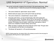
The blower will operate for a 30 second post purge. The gas valve is de-energized, and the flame is de-energized at flame sense or at completion of Operation: Normal The control continually compares the set temp ... water temp. The control checks for more details outlining failure to light operations. 7 The blower will turn off for heat. 5. UHS Sequence of 4 sec trial. Gas valve opens and monitors flame sense. Blower starts pre-purge cycle as the ignitor heats up (20 Sec). 3. At proper ignitor temp, a 4 second trial begins. NOTE...
The blower will operate for a 30 second post purge. The gas valve is de-energized, and the flame is de-energized at flame sense or at completion of Operation: Normal The control continually compares the set temp ... water temp. The control checks for more details outlining failure to light operations. 7 The blower will turn off for heat. 5. UHS Sequence of 4 sec trial. Gas valve opens and monitors flame sense. Blower starts pre-purge cycle as the ignitor heats up (20 Sec). 3. At proper ignitor temp, a 4 second trial begins. NOTE...
Universal H Series Troubleshooting Guide
Page 8
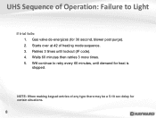
Retries 3 times until demand for certain situations. 8 UHS Sequence of Operation: Failure to retry every 60 minutes, until lockout (IF code). 4. Starts over at #2 of any type there may be a 5-10 sec delay for heat is stopped. Will continue to Light If trial fails: 1. NOTE: When making keypad entries of heating mode sequence. 3. Waits 60 minutes then retries 3 more times. 5. Gas valve de-energizes (for 30 second, blower post purge). 2.
Retries 3 times until demand for certain situations. 8 UHS Sequence of Operation: Failure to retry every 60 minutes, until lockout (IF code). 4. Starts over at #2 of any type there may be a 5-10 sec delay for heat is stopped. Will continue to Light If trial fails: 1. NOTE: When making keypad entries of heating mode sequence. 3. Waits 60 minutes then retries 3 more times. 5. Gas valve de-energizes (for 30 second, blower post purge). 2.

Universal H Series Troubleshooting Guide
Page 16
Manifold reading should be between 1.8"- 2.0" w.c for natural Gas or 6.8"- 7.0" w.c for proper gas line sizing. 16 Step 2 The static & load values should be within the levels listed on the data plate, example on Page 17. Step 1 Measure the outlet manifold pressure (valve on / energized). NOTE: Please refer to Installation Manual for propane. How To: Test/Adjust Gas Pressure Measure the inlet static pressure (valve off) & load pressure (valve on / energized), as shown below.
Manifold reading should be between 1.8"- 2.0" w.c for natural Gas or 6.8"- 7.0" w.c for proper gas line sizing. 16 Step 2 The static & load values should be within the levels listed on the data plate, example on Page 17. Step 1 Measure the outlet manifold pressure (valve on / energized). NOTE: Please refer to Installation Manual for propane. How To: Test/Adjust Gas Pressure Measure the inlet static pressure (valve off) & load pressure (valve on / energized), as shown below.
Universal H Series Troubleshooting Guide
Page 17
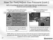
...low, go to step 4. Once removed, increase pressure by rotating valve clockwise, (counter clockwise to step 4. Remove plug. IF it does, continue to reduce pressure). *NOTE: Before any adjustment occurs, verify inlet gas pressure meets the requirement set forth by the data plate on the ...heater. Verify heater specifications off the heater plate (bottom front inside heater) Step 3 Step 4 *Adjust the manifold pressure (at the gas valve) IF inlet pressures are correct AND the manifold pressure is within range, then your manifold pressure should be correct per factory settings. IF ...
...low, go to step 4. Once removed, increase pressure by rotating valve clockwise, (counter clockwise to step 4. Remove plug. IF it does, continue to reduce pressure). *NOTE: Before any adjustment occurs, verify inlet gas pressure meets the requirement set forth by the data plate on the ...heater. Verify heater specifications off the heater plate (bottom front inside heater) Step 3 Step 4 *Adjust the manifold pressure (at the gas valve) IF inlet pressures are correct AND the manifold pressure is within range, then your manifold pressure should be correct per factory settings. IF ...

Universal H Series Troubleshooting Guide
Page 19
... Blower Vacuum Switch open Bad board or secondary high voltage fault Communication Error Between Control Module and Display Interface Assembly Bad board Flame present with Gas Valve not energized. Ignition Failure Ignitor Circuit Open Water Pressure Switch, Vent Pressure Switch, or Temperature Limit Switch Fault Voltage polarity reversed, low voltage detected Keypad...
... Blower Vacuum Switch open Bad board or secondary high voltage fault Communication Error Between Control Module and Display Interface Assembly Bad board Flame present with Gas Valve not energized. Ignition Failure Ignitor Circuit Open Water Pressure Switch, Vent Pressure Switch, or Temperature Limit Switch Fault Voltage polarity reversed, low voltage detected Keypad...

Universal H Series Troubleshooting Guide
Page 20
...5") FDXLFSK1930 FDXLFSK1930 Fuse Kit FDXLWPS1930 FDXLWPS1930 Water Pressure Switch FDXLBVS1930 FDXLBVS1930 Blower Vacuum Switch FDXLBRN1930 FDXLBRN1930 Burner Kit *FDXLGSV0001 FDXLGSV1500N Gas Valve (Natural Gas) FDXLGSV002 FDXLGSV1500P Gas Valve (Propane) FDXLVPS1930 FDXLVPS1930 Vent Pressure Switch FDXLHLI1930 FDXLHLI1930 High Limit Kit (temperature limits) *FDXLBKP1932 *FDXLBKP1932 Display/Bezel/Keypad ... Blower Tube Kit IDXL2DB1930 IDXL2DB1930 Prior 07/16-Display Board (only) FDXLEGL1931 FDXLEGL1931 Exhaust Gas Limit Switch FDXLBKP1930 FDXLBKP1930 Prior 07/16-Bezel/Keypad Assy.
...5") FDXLFSK1930 FDXLFSK1930 Fuse Kit FDXLWPS1930 FDXLWPS1930 Water Pressure Switch FDXLBVS1930 FDXLBVS1930 Blower Vacuum Switch FDXLBRN1930 FDXLBRN1930 Burner Kit *FDXLGSV0001 FDXLGSV1500N Gas Valve (Natural Gas) FDXLGSV002 FDXLGSV1500P Gas Valve (Propane) FDXLVPS1930 FDXLVPS1930 Vent Pressure Switch FDXLHLI1930 FDXLHLI1930 High Limit Kit (temperature limits) *FDXLBKP1932 *FDXLBKP1932 Display/Bezel/Keypad ... Blower Tube Kit IDXL2DB1930 IDXL2DB1930 Prior 07/16-Display Board (only) FDXLEGL1931 FDXLEGL1931 Exhaust Gas Limit Switch FDXLBKP1930 FDXLBKP1930 Prior 07/16-Bezel/Keypad Assy.

Universal H Series Troubleshooting Guide
Page 29
... ICB: FDXLICB1930 29 Is low voltage wiring damaged, pinched, or worn? NO Is blower vacuum switch wiring damaged, pinched, or worn? NO Is gas valve wiring damaged, pinched, or worn? NO Is water pressure switch wiring damaged, pinched, or worn? NO YES YES YES YES Replace wire harness: FDXLWHA1930... OR pressure switch if damaged: FDXLWPS1930 Replace wire harness: FDXLWHA1930 OR vacuum switch if damaged: FDXLBVS1930 Replace wire harness: FDXLWHA1930 OR Replace gas valve: Please refer to (pg. 20) 3. Open FC3 &/or F1 Fuse Open FC3 &/or F1 Fuse Check the remote connection/high limits Test...
... ICB: FDXLICB1930 29 Is low voltage wiring damaged, pinched, or worn? NO Is blower vacuum switch wiring damaged, pinched, or worn? NO Is gas valve wiring damaged, pinched, or worn? NO Is water pressure switch wiring damaged, pinched, or worn? NO YES YES YES YES Replace wire harness: FDXLWHA1930... OR pressure switch if damaged: FDXLWPS1930 Replace wire harness: FDXLWHA1930 OR vacuum switch if damaged: FDXLBVS1930 Replace wire harness: FDXLWHA1930 OR Replace gas valve: Please refer to (pg. 20) 3. Open FC3 &/or F1 Fuse Open FC3 &/or F1 Fuse Check the remote connection/high limits Test...

Universal H Series Troubleshooting Guide
Page 30
IF OK, go to step 3C. IF damaged, replace the wire harness (pg. 20). Inspect gas valve wiring Step 3D With power off , inspect the water pressure switch wiring for damage. IF damaged, replace the wire harness (pg. 20). Open FC3 &/or ... Step 3C With power off , inspect the blower vacuum switch wiring for damage. IF OK, go to step 3D. 30 With power off, inspect the gas valve wiring for damage. IF damaged, repair/replace (pg. 20). IF OK, go to step 3B. IF OK, go to step 3E. IF damaged, replace the...
IF OK, go to step 3C. IF damaged, replace the wire harness (pg. 20). Inspect gas valve wiring Step 3D With power off , inspect the water pressure switch wiring for damage. IF damaged, replace the wire harness (pg. 20). Open FC3 &/or ... Step 3C With power off , inspect the blower vacuum switch wiring for damage. IF OK, go to step 3D. 30 With power off, inspect the gas valve wiring for damage. IF damaged, repair/replace (pg. 20). IF OK, go to step 3B. IF OK, go to step 3E. IF damaged, replace the...

Universal H Series Troubleshooting Guide
Page 31
... kit (pg. 20). IF OK, go to ground. Inspect ICB wiring. Open FC3 &/or F1 Fuse (cont.) When testing the gas valve, if continuity appears between any terminal shows continuity, replace the gas valve (pg. 20). IF wiring is not shorted ICB wiring Step 3E Step 3F With power off, measure resistance, comparing each... OK and the problem still exists, replace the ICB (pg. 20) 31 IF any wires and ground, then this implies a short has occurred and the gas valve will need to be replaced (refer to pg. 20 for part number). 3.
... kit (pg. 20). IF OK, go to ground. Inspect ICB wiring. Open FC3 &/or F1 Fuse (cont.) When testing the gas valve, if continuity appears between any terminal shows continuity, replace the gas valve (pg. 20). IF wiring is not shorted ICB wiring Step 3E Step 3F With power off, measure resistance, comparing each... OK and the problem still exists, replace the ICB (pg. 20) 31 IF any wires and ground, then this implies a short has occurred and the gas valve will need to be replaced (refer to pg. 20 for part number). 3.
Universal H Series Troubleshooting Guide
Page 44
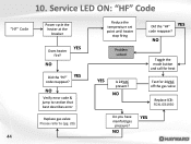
NO Toggle the mode button and call for 24VAC off the gas valve Replace ICB: FDXLICB1930 Do you have YES manifold gas pressure? NO NO Did the "HF" YES code reappear? Service LED ON: "HF" Code "HF" Code Power cycle the heater at the breaker Does heater YES fire? NO Verify error code & jump to section that best describes error Replace gas valve: Please refer to (pg. 20) 44 Reduce the temperature set point until heater stop firing Problem solved Did the "HF" YES code reappear? 10. NO Test for heat YES Is 24VAC present?
NO Toggle the mode button and call for 24VAC off the gas valve Replace ICB: FDXLICB1930 Do you have YES manifold gas pressure? NO NO Did the "HF" YES code reappear? Service LED ON: "HF" Code "HF" Code Power cycle the heater at the breaker Does heater YES fire? NO Verify error code & jump to section that best describes error Replace gas valve: Please refer to (pg. 20) 44 Reduce the temperature set point until heater stop firing Problem solved Did the "HF" YES code reappear? 10. NO Test for heat YES Is 24VAC present?
Universal H Series Troubleshooting Guide
Page 45
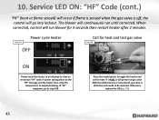
.... IF power cycling clears to the "HF" message and the heater fires, drop the temperature to toggle the heater and call for heat and test gas valve Step 10B ON Power cycle the heater, in an attempt to be replaced. Press the mode button to suspend heating. IF 24VAC is still present... at gas valve AND manifold pressure is not present, gas valve is off, the control will run until corrected. Otherwise, replace the ICB (pg. 20). 45 Power cycle heater Step 10A OFF Call...
.... IF power cycling clears to the "HF" message and the heater fires, drop the temperature to toggle the heater and call for heat and test gas valve Step 10B ON Power cycle the heater, in an attempt to be replaced. Press the mode button to suspend heating. IF 24VAC is still present... at gas valve AND manifold pressure is not present, gas valve is off, the control will run until corrected. Otherwise, replace the ICB (pg. 20). 45 Power cycle heater Step 10A OFF Call...
Universal H Series Troubleshooting Guide
Page 52
... ON? NO NO Correct inlet gas pressure Adjust manifold gas pressure Replace gas valve: Replace ICB: 52 Please refer to gas valve during call for heat pressure correct? NO Turn on main gas supply & retest Go to section B (next page) On ICB, verify flame Inspect gas YES Is heater's gas YES sensor & gas valve valve in heater valve ON? YES Is there manifold...
... ON? NO NO Correct inlet gas pressure Adjust manifold gas pressure Replace gas valve: Replace ICB: 52 Please refer to gas valve during call for heat pressure correct? NO Turn on main gas supply & retest Go to section B (next page) On ICB, verify flame Inspect gas YES Is heater's gas YES sensor & gas valve valve in heater valve ON? YES Is there manifold...
Universal H Series Troubleshooting Guide
Page 53
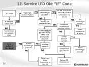
NO Inspect and/or clean burner tubes & orifices Replace with new burner kit: FDXLBRN1930 OR Gas Valve (includes orifices): (pg. 20) YES Are burner tubes & orifices damaged? NO Replace flame sensor: IDXLFLS1930 Check for damaged OR wrong blower air inlet plate NO Is plate YES damaged/ wrong? 12. NO Contact tech support: (908) 355-7995 53 Service LED ON: "IF" Code Section B (continued from previous page) Is correct flame YES sensor installed OR damaged?
NO Inspect and/or clean burner tubes & orifices Replace with new burner kit: FDXLBRN1930 OR Gas Valve (includes orifices): (pg. 20) YES Are burner tubes & orifices damaged? NO Replace flame sensor: IDXLFLS1930 Check for damaged OR wrong blower air inlet plate NO Is plate YES damaged/ wrong? 12. NO Contact tech support: (908) 355-7995 53 Service LED ON: "IF" Code Section B (continued from previous page) Is correct flame YES sensor installed OR damaged?

Universal H Series Troubleshooting Guide
Page 54
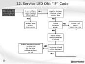
Flame sensor & gas valve Step 12C Verify that the gas valve, inside the heater, is in the "ON" position. IF NOT, open gas supply. IF OK, go to the ICB. IF correct, proceed to step 12D. 54 Ensure gas static, load, and manifold pressures are both securely fastened to step 12C. IF correct, go to ...step 12B. IF NOT, rotate knob to Step 12F. IF NOT, go to Step 12E. Service LED ON: "IF" Code Inspect main gas supply Step 12A Verify gas valve is ON Step 12B IF "Ignition Failure", Ensure main gas supply is in the ON position. IF ON, go to ON position. 12. Verify...
Flame sensor & gas valve Step 12C Verify that the gas valve, inside the heater, is in the "ON" position. IF NOT, open gas supply. IF OK, go to the ICB. IF correct, proceed to step 12D. 54 Ensure gas static, load, and manifold pressures are both securely fastened to step 12C. IF correct, go to ...step 12B. IF NOT, rotate knob to Step 12F. IF NOT, go to Step 12E. Service LED ON: "IF" Code Inspect main gas supply Step 12A Verify gas valve is ON Step 12B IF "Ignition Failure", Ensure main gas supply is in the ON position. IF ON, go to ON position. 12. Verify...

Universal H Series Troubleshooting Guide
Page 55
.... 20). Inspect orifices & burner tubes Step 12H Check for blockage. Service LED ON: "IF" Code (cont.) Voltage/pressure off gas valve Step 12E Verify correct flame sensor Step 12F Verify 22-28VAC off gas valve during ignition trial. IF 3" is installed OR IF sensor is 5". Verify blower air inlet plate Step 12G Verify that... support (908) 355-7995. 12. IF wrong or damaged contact tech support (908) 355- 7995. Clean as required. IF present & no pressure (manometer attached), replace valve. IF correct, go to step 12G. IF OK, go to step 12H. 55 Inspect...
.... 20). Inspect orifices & burner tubes Step 12H Check for blockage. Service LED ON: "IF" Code (cont.) Voltage/pressure off gas valve Step 12E Verify correct flame sensor Step 12F Verify 22-28VAC off gas valve during ignition trial. IF 3" is installed OR IF sensor is 5". Verify blower air inlet plate Step 12G Verify that... support (908) 355-7995. 12. IF wrong or damaged contact tech support (908) 355- 7995. Clean as required. IF present & no pressure (manometer attached), replace valve. IF correct, go to step 12G. IF OK, go to step 12H. 55 Inspect...


