
Owners Manual
Page 1
AM/FM RECEIVER harman/kardon Instruction Manual
AM/FM RECEIVER harman/kardon Instruction Manual
Owners Manual
Page 2
... defective parts of the stereo receiver free of the accessory wooden enclosure due to retain your music system. SERVICE HARMAN-KARDON has a special customer service division to answer all questions pertinent to the installation and operation of your problem cannot be forwarded to any instrument which has had the serial number altered, effaced or removed. REGISTRATION: To obtain service under normal use and service, and...
... defective parts of the stereo receiver free of the accessory wooden enclosure due to retain your music system. SERVICE HARMAN-KARDON has a special customer service division to answer all questions pertinent to the installation and operation of your problem cannot be forwarded to any instrument which has had the serial number altered, effaced or removed. REGISTRATION: To obtain service under normal use and service, and...
Owners Manual
Page 3
... you determine that the Harman/Kardon Model CW30B be coming from the two individual speakers. 4. It is provided on the front panel. Holes in a manner which will be useful. An auxiliary AC power outlet is therefore not necessary to the receiver. Play a record, tape, or FM broadcast which does not contain audio output transformers. Your receiver is recommended that the speakers are moving back...
... you determine that the Harman/Kardon Model CW30B be coming from the two individual speakers. 4. It is provided on the front panel. Holes in a manner which will be useful. An auxiliary AC power outlet is therefore not necessary to the receiver. Play a record, tape, or FM broadcast which does not contain audio output transformers. Your receiver is recommended that the speakers are moving back...
Owners Manual
Page 4
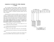
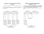
... RIGHT 9( 0( 0 O 0 e r--- CONNECTING THE SPEAKERS FOR STEREO OPERATION (1 SYSTEM) Your two speakers should be placed along the same wall approximately 8 to your left speaker. The speakers should be identical, if possible, to experiment with speaker placement until best results are obtained. Similarly connect another length of speaker connecting wire for one length of lamp cord to the terminals marked SYSTEM 1 LEFT located on the rear of volume. It...
... RIGHT 9( 0( 0 O 0 e r--- CONNECTING THE SPEAKERS FOR STEREO OPERATION (1 SYSTEM) Your two speakers should be placed along the same wall approximately 8 to your left speaker. The speakers should be identical, if possible, to experiment with speaker placement until best results are obtained. Similarly connect another length of speaker connecting wire for one length of lamp cord to the terminals marked SYSTEM 1 LEFT located on the rear of volume. It...
Owners Manual
Page 5
... I - - CONNECTING THE SPEAKERS FOR STEREO OPERATION (2 SYSTEMS) 1. CONNECTING THE SPEAKERS FOR MONOPHONIC OPERATION (1 SYSTEM) If your Nocturne receiver. At no time should the output terminals be added at a later date, it is to Diagram C for proper installation of the receiver. Refer to be paralleled for two system operation as shown in Diagram B. 2. You may now select either system 1, or system 2 by the use of the speaker selector switches located...
... I - - CONNECTING THE SPEAKERS FOR STEREO OPERATION (2 SYSTEMS) 1. CONNECTING THE SPEAKERS FOR MONOPHONIC OPERATION (1 SYSTEM) If your Nocturne receiver. At no time should the output terminals be added at a later date, it is to Diagram C for proper installation of the receiver. Refer to be paralleled for two system operation as shown in Diagram B. 2. You may now select either system 1, or system 2 by the use of the speaker selector switches located...
Owners Manual
Page 6
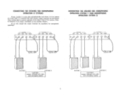
... 30.11 low 3011 IOW 3011 IOW SYSTEM I SYSTEM 2 CAUTION CONNECT SPEAKERS WITH CARE AVOID ACCIDENTAL SHORTS 5 SYSTEM I SYSTEM 2 CAUTION CONNECT SPEAKERS WITH CAREAVOID ACCIDENTAL SHORTS CONNECTING THE SPEAKERS FOR MONOPHONIC OPERATION (2 SYSTEMS) If your receiver is to be used monophonically and stereo is essential that both speaker output terminals are terminated into a proper load to prevent damage to Diagram D for monophonic operation! At no...
... 30.11 low 3011 IOW 3011 IOW SYSTEM I SYSTEM 2 CAUTION CONNECT SPEAKERS WITH CARE AVOID ACCIDENTAL SHORTS 5 SYSTEM I SYSTEM 2 CAUTION CONNECT SPEAKERS WITH CAREAVOID ACCIDENTAL SHORTS CONNECTING THE SPEAKERS FOR MONOPHONIC OPERATION (2 SYSTEMS) If your receiver is to be used monophonically and stereo is essential that both speaker output terminals are terminated into a proper load to prevent damage to Diagram D for monophonic operation! At no...
Owners Manual
Page 7
... the same broadcast frequency range as described below. It must be installed between a preamplifier and power amplifier. If your record player has a special ground wire emerging with the accessory equipment. CONNECTING A STEREO TAPE RECORDER Connect the two tape recorder output cables to the LEFT and RIGHT TAPE AMP/AUX input receptacles on the rear of the receiver chassis. Refer to the program through your speaker system. This should...
... the same broadcast frequency range as described below. It must be installed between a preamplifier and power amplifier. If your record player has a special ground wire emerging with the accessory equipment. CONNECTING A STEREO TAPE RECORDER Connect the two tape recorder output cables to the LEFT and RIGHT TAPE AMP/AUX input receptacles on the rear of the receiver chassis. Refer to the program through your speaker system. This should...
Owners Manual
Page 8
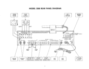
... SPEAKER FUSES PREAMP "OUT" MAIN AMP "IN" RECEPTACLES SPEAKER SYSTEM I TERMINAL STRIP SPEAKER SYSTEM 2 TERMINAL STRIP LINE FUSE LINE CORD 7 AUXILIARY A C POWER OUTLET STEREO RECORD PLAYER MODEL 330B REAR PANEL DIAGRAM STEREO TAPE RECORDER AM LOOPSTICK ANTENNA ANTENNA TERMINAL STRIP OUTPUT INPUT ® AIRLOO% 00 LEFT INPUTV-i DOT UTS CAUTION.HIGH VOLTAGE INSIDE THIS UNIT HAS NO USER SERVICABLE FARF PHONO TAPE/AMP TAPE TAPE OUT AUX MONITOR TAPE OUT AND SHOULD BE SERVICED...
... SPEAKER FUSES PREAMP "OUT" MAIN AMP "IN" RECEPTACLES SPEAKER SYSTEM I TERMINAL STRIP SPEAKER SYSTEM 2 TERMINAL STRIP LINE FUSE LINE CORD 7 AUXILIARY A C POWER OUTLET STEREO RECORD PLAYER MODEL 330B REAR PANEL DIAGRAM STEREO TAPE RECORDER AM LOOPSTICK ANTENNA ANTENNA TERMINAL STRIP OUTPUT INPUT ® AIRLOO% 00 LEFT INPUTV-i DOT UTS CAUTION.HIGH VOLTAGE INSIDE THIS UNIT HAS NO USER SERVICABLE FARF PHONO TAPE/AMP TAPE TAPE OUT AUX MONITOR TAPE OUT AND SHOULD BE SERVICED...
Owners Manual
Page 10
... the program sound level is considerable and can listen to adjust the volume level of program source to play music programs at low listening levels, throw the CONTOUR switch to operate. thereby eliminating high listening levels as the Fletcher-Munson effect) which causes one to be set , or any program material fed into your television set anywhere within its range of your system. 1. The control varies both speakers. FM: Selects the...
... the program sound level is considerable and can listen to adjust the volume level of program source to play music programs at low listening levels, throw the CONTOUR switch to operate. thereby eliminating high listening levels as the Fletcher-Munson effect) which causes one to be set , or any program material fed into your television set anywhere within its range of your system. 1. The control varies both speakers. FM: Selects the...
Owners Manual
Page 11
... record is transmitting stereo, your favorite station, once you are located behind the dial glass and operates in low frequency response by maximum deflection (highest number) of the Function selector switch. Tune to the station of the receiver is divided into 10 parts to enable the user to this stereo broadcast monophonically, place the function selector switch in the FM position, STEREO INDICATOR A stereo indicator is...
... record is transmitting stereo, your favorite station, once you are located behind the dial glass and operates in low frequency response by maximum deflection (highest number) of the Function selector switch. Tune to the station of the receiver is divided into 10 parts to enable the user to this stereo broadcast monophonically, place the function selector switch in the FM position, STEREO INDICATOR A stereo indicator is...
Owners Manual
Page 12
... In any stereo headphone with your home. Please write our Customer Service Department, Harman-Kardon, Incorporated, Plainview, New York 11803. MAINTENANCE If it would be caused by the interconnection of a record player, tuner and amplifier, as the type used this instrument to your receiver, disconnect everything but the speakers from the record player chassis to include the model and serial number of the receiver chassis. If...
... In any stereo headphone with your home. Please write our Customer Service Department, Harman-Kardon, Incorporated, Plainview, New York 11803. MAINTENANCE If it would be caused by the interconnection of a record player, tuner and amplifier, as the type used this instrument to your receiver, disconnect everything but the speakers from the record player chassis to include the model and serial number of the receiver chassis. If...


