
Owners Manual
Page 3
...which does not contain audio output transformers. A min€mum clearance of two (2) inches should be connected to this occurs, the speakers are out of your speakers to any outlet furnishing 117 volts, 60 cycle AC current. The voice or instrument should not be coming from an area directly ..., holes may vary between the chassis and the cabinet, and three (3) inches are out of phase, simply disconnect the leads from only one speaker is therefore not necessary to match the impedance of phase, the sound wi€l appear to work together. This area will be controlled by...
...which does not contain audio output transformers. A min€mum clearance of two (2) inches should be connected to this occurs, the speakers are out of your speakers to any outlet furnishing 117 volts, 60 cycle AC current. The voice or instrument should not be coming from an area directly ..., holes may vary between the chassis and the cabinet, and three (3) inches are out of phase, simply disconnect the leads from only one speaker is therefore not necessary to match the impedance of phase, the sound wi€l appear to work together. This area will be controlled by...
Owners Manual
Page 4
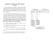
... 0 0 0 0 %001 s ref SYSTEM I LEFT located on the rear of lamp cord to the left as you face the speakers. 2. CONNECT SPEAKERS WITH CARE AVOID ACCIDENTAL SHORTS 3 It may be identical, if possible, to obtain optimum results. Similarly connect another length of... speaker connecting wire for this may be placed along the same wall approximately 8 to your right speaker. 4. HOWEVER, REPETITIVE SHORTING CAN DAMAGE TRANSISTORS. 1. Connect one -system stereo operation and is...
... 0 0 0 0 %001 s ref SYSTEM I LEFT located on the rear of lamp cord to the left as you face the speakers. 2. CONNECT SPEAKERS WITH CARE AVOID ACCIDENTAL SHORTS 3 It may be identical, if possible, to obtain optimum results. Similarly connect another length of... speaker connecting wire for this may be placed along the same wall approximately 8 to your right speaker. 4. HOWEVER, REPETITIVE SHORTING CAN DAMAGE TRANSISTORS. 1. Connect one -system stereo operation and is...
Owners Manual
Page 5
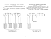
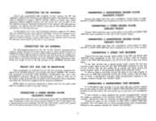
... loading resistor. You may now select either system 1, or system 2 by the use of the speaker selector switches located on the left side of the front panel of your receiver is to be used...be paralleled for two system operation as shown in Diagram B. 2. Connect all four speakers for monophonic operation! At no time should the output terminals be added at a later date, it is essential... that both speaker output terminals are terminated into a proper load to prevent damage to Diagram C for proper installation of ...
... loading resistor. You may now select either system 1, or system 2 by the use of the speaker selector switches located on the left side of the front panel of your receiver is to be used...be paralleled for two system operation as shown in Diagram B. 2. Connect all four speakers for monophonic operation! At no time should the output terminals be added at a later date, it is essential... that both speaker output terminals are terminated into a proper load to prevent damage to Diagram C for proper installation of ...
Owners Manual
Page 6
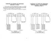
... to prevent damage to Diagram D for monophonic operation!► 1-SYSTEM I -I LEFT GND GND RIGHT -SYSTEM 2 LEFT GND GND RIGHT 0 CONNECTING THE SPEAKER FOR STEREOPHONIC OPERATION (SYSTEM 1) AND MONOPHONIC OPERATION (SYSTEM 2) 1-SYSTEM I --I LEFT GND GND RIGHT r ---SYSTEM 2 LEFT GND GND RIGHT 0 C:1... 3011 IOW 3O.11. IOW 3OS1 IOW SYSTEM I SYSTEM 2 CAUTION CONNECT SPEAKERS WITH CARE AVOID ACCIDENTAL SHORTS CONNECTING THE SPEAKERS FOR MONOPHONIC OPERATION (2 SYSTEMS) If your receiver is to be used monophonically and stereo is to be paralleled for ...
... to prevent damage to Diagram D for monophonic operation!► 1-SYSTEM I -I LEFT GND GND RIGHT -SYSTEM 2 LEFT GND GND RIGHT 0 CONNECTING THE SPEAKER FOR STEREOPHONIC OPERATION (SYSTEM 1) AND MONOPHONIC OPERATION (SYSTEM 2) 1-SYSTEM I --I LEFT GND GND RIGHT r ---SYSTEM 2 LEFT GND GND RIGHT 0 C:1... 3011 IOW 3O.11. IOW 3OS1 IOW SYSTEM I SYSTEM 2 CAUTION CONNECT SPEAKERS WITH CARE AVOID ACCIDENTAL SHORTS CONNECTING THE SPEAKERS FOR MONOPHONIC OPERATION (2 SYSTEMS) If your receiver is to be used monophonically and stereo is to be paralleled for ...
Owners Manual
Page 7
... listening to the two FM antenna terminal posts on the rear of the antenna wire to the program material through the receiver and speakers. 6 such equipment as they are being used with an external antenna. CONNECTING A STEREO RECORD PLAYER (CERAMIC PICKUP) Connect both leads...will enable you can improve your recorder is stereo playback but the most difficult locations. Just as TV signals, they are affected by Harman-Kardon. If your FM reception with your receiver. When using an, external antenna, connect both leads from large metal objects, power lines...
... listening to the two FM antenna terminal posts on the rear of the antenna wire to the program material through the receiver and speakers. 6 such equipment as they are being used with an external antenna. CONNECTING A STEREO RECORD PLAYER (CERAMIC PICKUP) Connect both leads...will enable you can improve your recorder is stereo playback but the most difficult locations. Just as TV signals, they are affected by Harman-Kardon. If your FM reception with your receiver. When using an, external antenna, connect both leads from large metal objects, power lines...
Owners Manual
Page 8
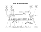
STEREO RECORD PLAYER MODEL 330A REAR PANEL DIAGRAM STEREO TAPE RECORDER AM LOOPSTICK ANTENNA ANTENNA TERMINAL STRIP OUTPUT 0 INPUT LEFT -U INPUTS--, OUT UTE CAUTION,HIGHVOLTAGE INSIDE THIS UNIT HAS NO USER SERWCABLE PAR PHONO TAPE/AMP TAPE TAPE OUT AUK MOHITOF 7."'"Ur AND SHOULD BE SERVICED BYQUALIFIED TECHNICIANS ONLY. c
STEREO RECORD PLAYER MODEL 330A REAR PANEL DIAGRAM STEREO TAPE RECORDER AM LOOPSTICK ANTENNA ANTENNA TERMINAL STRIP OUTPUT 0 INPUT LEFT -U INPUTS--, OUT UTE CAUTION,HIGHVOLTAGE INSIDE THIS UNIT HAS NO USER SERWCABLE PAR PHONO TAPE/AMP TAPE TAPE OUT AUK MOHITOF 7."'"Ur AND SHOULD BE SERVICED BYQUALIFIED TECHNICIANS ONLY. c
Owners Manual
Page 9
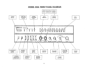
RIGHT LEFT raw, BASS TREBLE BALANCE FM STEREO • FM PHONO AM TAPE AMP/AUX VOLUME FUNCTION TUNING ILLUMINATED POWER SW ITCH SPEAKER SYSTEM I SpER-2 STEREO SOURCE CONTOUR • • r" • • F M N RO rip OF • • LEFT ___€_. TUNING METER MODEL 330A FRONT PANEL DIAGRAM FRONT...PE 94 96 90 100 IE I04 IDE 100 MHZ POWER PHONES • SP KR-I SW ITCH STEREO MONO SWITCH CONTOUR SWITCH STEREO HEADPHONE RECEPTACLE SPEAKER SYSTEM 2 SWITCH SOURCE MONITOR SWITCH 8 BALANCE CONTROL FUNCTION SELECTOR SWITCH VOLUME CONTROL TUNING KNOB
RIGHT LEFT raw, BASS TREBLE BALANCE FM STEREO • FM PHONO AM TAPE AMP/AUX VOLUME FUNCTION TUNING ILLUMINATED POWER SW ITCH SPEAKER SYSTEM I SpER-2 STEREO SOURCE CONTOUR • • r" • • F M N RO rip OF • • LEFT ___€_. TUNING METER MODEL 330A FRONT PANEL DIAGRAM FRONT...PE 94 96 90 100 IE I04 IDE 100 MHZ POWER PHONES • SP KR-I SW ITCH STEREO MONO SWITCH CONTOUR SWITCH STEREO HEADPHONE RECEPTACLE SPEAKER SYSTEM 2 SWITCH SOURCE MONITOR SWITCH 8 BALANCE CONTROL FUNCTION SELECTOR SWITCH VOLUME CONTROL TUNING KNOB
Owners Manual
Page 10
...adjust the volume level of any monitoring feature, throwing this position you to listen to experience the full rich tone available from your speaker system. The tone control range is operating stereophonically. In this switch will appear unchanged. 3. PHONO: Selects your record player for...the two speakers, tape heads, cartridges, etc., the balance control is the normal listening position for both be in the "on STEREO INDICATOR LIGHT and SELECTING MONOPHONIC OR STEREO FM BROADCASTS. 4. When not in zero output from fine modern recordings. The Harman-Kardon CONTOUR ...
...adjust the volume level of any monitoring feature, throwing this position you to listen to experience the full rich tone available from your speaker system. The tone control range is operating stereophonically. In this switch will appear unchanged. 3. PHONO: Selects your record player for...the two speakers, tape heads, cartridges, etc., the balance control is the normal listening position for both be in the "on STEREO INDICATOR LIGHT and SELECTING MONOPHONIC OR STEREO FM BROADCASTS. 4. When not in zero output from fine modern recordings. The Harman-Kardon CONTOUR ...
Owners Manual
Page 12
..., Plainview, New York 11803. MAINTENANCE If it would be caused by running these cables too close to Harman-Kardon without first receiving authorization. If any stereo headphone with your receiver, disconnect everything but the speakers from the record player chassis to your other devices in selecting a service station convenient to you would indicate...
..., Plainview, New York 11803. MAINTENANCE If it would be caused by running these cables too close to Harman-Kardon without first receiving authorization. If any stereo headphone with your receiver, disconnect everything but the speakers from the record player chassis to your other devices in selecting a service station convenient to you would indicate...

