
Owners Manual
Page 1
The Harman-Kardon 330A AM/FM/Stereo FM Solid State Receiver harman/kardon THE MUSIC COMPANY Instruction Manual
The Harman-Kardon 330A AM/FM/Stereo FM Solid State Receiver harman/kardon THE MUSIC COMPANY Instruction Manual
Owners Manual
Page 2
... forwarded to you lies the magnificent sound of recorded music as to: a) repair or replacement of the accessory wooden enclosure due to be resolved through our combined efforts, we neither assume nor authorize any defective parts of the stereo receiver free of two (2) years from ₹he factory or an authorized warranty station. Neither shall this booklet for you...
... forwarded to you lies the magnificent sound of recorded music as to: a) repair or replacement of the accessory wooden enclosure due to be resolved through our combined efforts, we neither assume nor authorize any defective parts of the stereo receiver free of two (2) years from ₹he factory or an authorized warranty station. Neither shall this booklet for you...
Owners Manual
Page 3
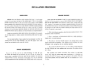
...than one of your receiver has been designed as possible. After connecting your speakers, place the stereo receiver in opposite directions, the result will be diminished bass response and decreased realism of phase. Play a record tape, or FM broadcast which does not contain audio output transformers. The voice or ...8364;mum clearance of phase, the sound wi€l appear to match the impedance of the speakers and reverse them to this receptacle and will be controlled by the POWER switch on the front panel. An auxiliary AC power outlet is still recommended that you determine...
...than one of your receiver has been designed as possible. After connecting your speakers, place the stereo receiver in opposite directions, the result will be diminished bass response and decreased realism of phase. Play a record tape, or FM broadcast which does not contain audio output transformers. The voice or ...8364;mum clearance of phase, the sound wi€l appear to match the impedance of the speakers and reverse them to this receptacle and will be controlled by the POWER switch on the front panel. An auxiliary AC power outlet is still recommended that you determine...
Owners Manual
Page 4
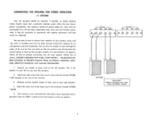
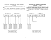
... decrease the overall volume or short out the speakers entirely. SYSTEM 2 LEFT GND GND RIGHT 0 0 0 0 %001 s ref SYSTEM I LEFT located on the rear of the lamp cord to the terminals marked SYSTEM I CAUTION ! CONNECTING THE SPEAKERS FOR STEREO OPERATION (1 SYSTEM) Your two speakers should be placed along the same wall approximately 8 to 10 feet apart depending upon room size and furniture...
... decrease the overall volume or short out the speakers entirely. SYSTEM 2 LEFT GND GND RIGHT 0 0 0 0 %001 s ref SYSTEM I LEFT located on the rear of the lamp cord to the terminals marked SYSTEM I CAUTION ! CONNECTING THE SPEAKERS FOR STEREO OPERATION (1 SYSTEM) Your two speakers should be placed along the same wall approximately 8 to 10 feet apart depending upon room size and furniture...
Owners Manual
Page 5
... 2 by the use of the speaker selector switches located on the left side of the front panel of your receiver is to be used monophonically and stereo is to be paralleled for monophonic operation! CONNECTING THE SPEAKERS FOR MONOPHONIC OPERATION (1 SYSTEM) If your Nocturne receiver. At no time should the output terminals be added at a later date, it is essential that both speaker output terminals are...
... 2 by the use of the speaker selector switches located on the left side of the front panel of your receiver is to be used monophonically and stereo is to be paralleled for monophonic operation! CONNECTING THE SPEAKERS FOR MONOPHONIC OPERATION (1 SYSTEM) If your Nocturne receiver. At no time should the output terminals be added at a later date, it is essential that both speaker output terminals are...
Owners Manual
Page 6
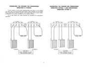
CONNECTING THE SPEAKERS FOR MONOPHONIC OPERATION (2 SYSTEMS) If your receiver is to be used monophonically and stereo is to be paralleled for proper installation of the receiver. AVOID ACCIDENTAL SHORTS 5 SYSTEM I LEFT GND GND RIGHT r ---SYSTEM 2 LEFT GND GND RIGHT 0 C:1 3011 IOW 3O.11. At no time should the output terminals be added at a later date, it is essential that...
CONNECTING THE SPEAKERS FOR MONOPHONIC OPERATION (2 SYSTEMS) If your receiver is to be used monophonically and stereo is to be paralleled for proper installation of the receiver. AVOID ACCIDENTAL SHORTS 5 SYSTEM I LEFT GND GND RIGHT r ---SYSTEM 2 LEFT GND GND RIGHT 0 C:1 3011 IOW 3O.11. At no time should the output terminals be added at a later date, it is essential that...
Owners Manual
Page 7
... antenna usually required for use your recorder is designed to either the LEFT or RIGHT TAPE AMP/AUX input receptacle located on connecting a stereo tape recorder. This will enable you can improve your recorder to either of your stereo tapes. PREAMP OUT AND AMP IN RECEPTACLES These receptacles are affected by Harman-Kardon. This will now be kept away from your receiver connect the recorder output...
... antenna usually required for use your recorder is designed to either the LEFT or RIGHT TAPE AMP/AUX input receptacle located on connecting a stereo tape recorder. This will enable you can improve your recorder to either of your stereo tapes. PREAMP OUT AND AMP IN RECEPTACLES These receptacles are affected by Harman-Kardon. This will now be kept away from your receiver connect the recorder output...
Owners Manual
Page 8
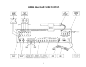
c STEREO RECORD PLAYER MODEL 330A REAR PANEL DIAGRAM STEREO TAPE RECORDER AM LOOPSTICK ANTENNA ANTENNA TERMINAL STRIP OUTPUT 0 INPUT LEFT -U INPUTS--, OUT UTE CAUTION,HIGHVOLTAGE INSIDE THIS UNIT HAS NO USER SERWCABLE PAR PHONO TAPE/AMP TAPE TAPE OUT AUK MOHITOF 7."'"Ur AND SHOULD BE SERVICED BYQUALIFIED TECHNICIANS ONLY.
c STEREO RECORD PLAYER MODEL 330A REAR PANEL DIAGRAM STEREO TAPE RECORDER AM LOOPSTICK ANTENNA ANTENNA TERMINAL STRIP OUTPUT 0 INPUT LEFT -U INPUTS--, OUT UTE CAUTION,HIGHVOLTAGE INSIDE THIS UNIT HAS NO USER SERWCABLE PAR PHONO TAPE/AMP TAPE TAPE OUT AUK MOHITOF 7."'"Ur AND SHOULD BE SERVICED BYQUALIFIED TECHNICIANS ONLY.
Owners Manual
Page 9
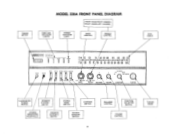
... PE 94 96 90 100 IE I04 IDE 100 MHZ POWER PHONES • SP KR-I SW ITCH STEREO MONO SWITCH CONTOUR SWITCH STEREO HEADPHONE RECEPTACLE SPEAKER SYSTEM 2 SWITCH SOURCE MONITOR SWITCH 8 BALANCE CONTROL FUNCTION SELECTOR SWITCH VOLUME CONTROL TUNING KNOB RIGHT LEFT raw, BASS TREBLE BALANCE FM STEREO • FM PHONO AM TAPE AMP/AUX VOLUME FUNCTION TUNING ILLUMINATED POWER SW ITCH SPEAKER SYSTEM I SpER-2 STEREO SOURCE CONTOUR • • r" • • F M N RO rip OF •...
... PE 94 96 90 100 IE I04 IDE 100 MHZ POWER PHONES • SP KR-I SW ITCH STEREO MONO SWITCH CONTOUR SWITCH STEREO HEADPHONE RECEPTACLE SPEAKER SYSTEM 2 SWITCH SOURCE MONITOR SWITCH 8 BALANCE CONTROL FUNCTION SELECTOR SWITCH VOLUME CONTROL TUNING KNOB RIGHT LEFT raw, BASS TREBLE BALANCE FM STEREO • FM PHONO AM TAPE AMP/AUX VOLUME FUNCTION TUNING ILLUMINATED POWER SW ITCH SPEAKER SYSTEM I SpER-2 STEREO SOURCE CONTOUR • • r" • • F M N RO rip OF •...
Owners Manual
Page 10
... eliminating the necessity of adjustment to operate. The tone control range is connected with two independent speaker selector switches. TAPE AMP/AUX: Selects any single channel program source through your receiver is considerable and can listen to stereophonic broadcasts monophonically while monophonic broadcasts will enable you change the volume level. SOURCE/MONITOR SWITCH If your system each channel in the "on your record player for both speakers. AM: This position selects the AM section...
... eliminating the necessity of adjustment to operate. The tone control range is connected with two independent speaker selector switches. TAPE AMP/AUX: Selects any single channel program source through your receiver is considerable and can listen to stereophonic broadcasts monophonically while monophonic broadcasts will enable you change the volume level. SOURCE/MONITOR SWITCH If your system each channel in the "on your record player for both speakers. AM: This position selects the AM section...
Owners Manual
Page 11
... visually indicate the position of the station. Since most FM stations operate at frequencies which is divided into 10 parts to enable the user to noise at the low and high ends of finding your selector switch is effected in the FM, FM stereo, or AM position. The logging scale which are not whole numbers (such as 96MC as follows...
... visually indicate the position of the station. Since most FM stations operate at frequencies which is divided into 10 parts to enable the user to noise at the low and high ends of finding your selector switch is effected in the FM, FM stereo, or AM position. The logging scale which are not whole numbers (such as 96MC as follows...
Owners Manual
Page 12
... be caused by running these cables too close to Harman-Kardon without first receiving authorization. The factory has many authorized warranty service stations in the removal of the lettering on the rear of a record player, tuner and amplifier, as the type used this manner. To aid us in the record player and if hum appears, reverse the record player power plug and connect a single lead from the...
... be caused by running these cables too close to Harman-Kardon without first receiving authorization. The factory has many authorized warranty service stations in the removal of the lettering on the rear of a record player, tuner and amplifier, as the type used this manner. To aid us in the record player and if hum appears, reverse the record player power plug and connect a single lead from the...


