
Owners Manual
Page 3
...the chassis and the cabinet, and three (3) inches are said to be controlled by the POWER switch on the rear panel of your speaker connections. This area will then be provided in phase. An auxiliary AC power outlet is still recommended that you determine that really effective ventilation...phase and correcting, if required, is therefore not necessary to work together. As an alternative, holes may vary between the two speakers. Both left and right speakers must be out of phase. The system will become warm under normal use and should appear to be connected in a manner ...
...the chassis and the cabinet, and three (3) inches are said to be controlled by the POWER switch on the rear panel of your speaker connections. This area will then be provided in phase. An auxiliary AC power outlet is still recommended that you determine that really effective ventilation...phase and correcting, if required, is therefore not necessary to work together. As an alternative, holes may vary between the two speakers. Both left and right speakers must be out of phase. The system will become warm under normal use and should appear to be connected in a manner ...
Owners Manual
Page 4
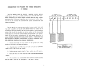
... an inconspicuous and neat installation. AVOID SHORTS - THE RECEIVER HAS BEEN DESIGNED TO PREVENT DAMAGE FROM ACCIDENTAL SHORTING; This is the speaker on your right speaker. 4. Attach the other end of the lamp cord to the terminals marked SYSTEM 1 LEFT located on the front panel is excellent... placement. It may be necessary to obtain optimum results. Lamp cord "zip cord" is in the SPKR-1 position. 3 I CAUTION CONNECT SPEAKERS WITH CARE AVOID ACCIDENTAL SHORTS Attach the other end of lamp cord to your receiver. Do not drive the staples or tacks through the center...
... an inconspicuous and neat installation. AVOID SHORTS - THE RECEIVER HAS BEEN DESIGNED TO PREVENT DAMAGE FROM ACCIDENTAL SHORTING; This is the speaker on your right speaker. 4. Attach the other end of the lamp cord to the terminals marked SYSTEM 1 LEFT located on the front panel is excellent... placement. It may be necessary to obtain optimum results. Lamp cord "zip cord" is in the SPKR-1 position. 3 I CAUTION CONNECT SPEAKERS WITH CARE AVOID ACCIDENTAL SHORTS Attach the other end of lamp cord to your receiver. Do not drive the staples or tacks through the center...
Owners Manual
Page 5
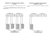
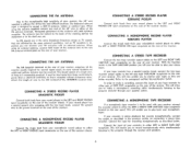
...) At no time should the output terminals be paralleled for two system operation as shown in Diagram B. 2. SYSTEM I -I LEFT GND GND RIGHT I-SYSTEM 2 - -I CAUTION CONNECT SPEAKER WITH CARE AVOID ACCIDENTAL SHORTS CONNECTING THE SPEAKERS FOR STEREO OPERATION (2 SYSTEMS) 1. You may now select either system 1, or system 2 by the use of the...
...) At no time should the output terminals be paralleled for two system operation as shown in Diagram B. 2. SYSTEM I -I LEFT GND GND RIGHT I-SYSTEM 2 - -I CAUTION CONNECT SPEAKER WITH CARE AVOID ACCIDENTAL SHORTS CONNECTING THE SPEAKERS FOR STEREO OPERATION (2 SYSTEMS) 1. You may now select either system 1, or system 2 by the use of the...
Owners Manual
Page 6
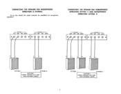
CONNECT SPEAKERS WITH CAREAVOID ACCIDENTAL SHORTS SYSTEM I SYSTEM 2 CAUTION ! CONNECTING THE SPEAKERS FOR MONOPHONIC OPERATION (2 SYSTEMS) At no time should the output terminals be paralleled for monophonic operation! SYSTEM I LEFT GND GND RIGHT r --SYSTEM 2 -i LEFT GND GND RIGHT O O e SYSTEM I SYSTEM 2 CAUTION CONNECT SPEAKERS WITH CARE AVOID ACCIDENTAL SHORTS 5 CONNECTING THE SPEAKER FOR STEREOPHONIC OPERATION (SYSTEM 1) AND MONOPHONIC OPERATION (SYSTEM 2) I-SYSTEM I -I LEFT GND GND RIGHT I-SYSTEM 2 LEFT GND GND RIGHT O Oe r -
CONNECT SPEAKERS WITH CAREAVOID ACCIDENTAL SHORTS SYSTEM I SYSTEM 2 CAUTION ! CONNECTING THE SPEAKERS FOR MONOPHONIC OPERATION (2 SYSTEMS) At no time should the output terminals be paralleled for monophonic operation! SYSTEM I LEFT GND GND RIGHT r --SYSTEM 2 -i LEFT GND GND RIGHT O O e SYSTEM I SYSTEM 2 CAUTION CONNECT SPEAKERS WITH CARE AVOID ACCIDENTAL SHORTS 5 CONNECTING THE SPEAKER FOR STEREOPHONIC OPERATION (SYSTEM 1) AND MONOPHONIC OPERATION (SYSTEM 2) I-SYSTEM I -I LEFT GND GND RIGHT I-SYSTEM 2 LEFT GND GND RIGHT O Oe r -
Owners Manual
Page 7
... of the receiver chassis. This will enable you to record monophonically while simultaneously listening to the program material through the receiver and speakers. 6 This will allow you to make a recording, connect the inputs of your tape recorder to either the LEFT or RIGHT... same broadcast frequency range as described below. In order to make a stereophonic recording while simultaneously listening to the program through your speaker system. Just as TV reception is sufficient for recording monophonically as TV signals, they are affected by the same external conditions. ...
... of the receiver chassis. This will enable you to record monophonically while simultaneously listening to the program material through the receiver and speakers. 6 This will allow you to make a recording, connect the inputs of your tape recorder to either the LEFT or RIGHT... same broadcast frequency range as described below. In order to make a stereophonic recording while simultaneously listening to the program through your speaker system. Just as TV reception is sufficient for recording monophonically as TV signals, they are affected by the same external conditions. ...
Owners Manual
Page 8
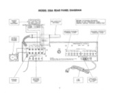
...JAPAN CX-2C GROUND SCREW ANTENNA TERMINAL STRIP LINE CORD AUXILIARY AC POWER OUTLET 7 FM--I A FUSE LA-3AG HARMAN-KARDON, INC., PLAINVIEW, N.Y MODEL 230A SPEAKERS 4-8 OR 1611 STATEN / L TSPEAGKEIEDR I - MODEL 230A REAR PANEL DIAGRAM STEREO TAPE RECORDER STEREO RECORD PLAYER ...OUTPUT -FoR 00 Lo INPUT Ro AM LOOPSTICK ANTENNA BEFORE ATTACHING SPEAKERS REFER TO THE PORTION OF YOUR OWNERS MANUAL "SPEAKER CONNECTION" SPEAKER SYSTEM-1 TERMINAL STRIP SPEAKER SYSTEM -2 TERMINAL STRIP SEE IAiLo1106 INPUTS PHONO TAPE/AMP TAPE TA?E MAG CER AUX ...
...JAPAN CX-2C GROUND SCREW ANTENNA TERMINAL STRIP LINE CORD AUXILIARY AC POWER OUTLET 7 FM--I A FUSE LA-3AG HARMAN-KARDON, INC., PLAINVIEW, N.Y MODEL 230A SPEAKERS 4-8 OR 1611 STATEN / L TSPEAGKEIEDR I - MODEL 230A REAR PANEL DIAGRAM STEREO TAPE RECORDER STEREO RECORD PLAYER ...OUTPUT -FoR 00 Lo INPUT Ro AM LOOPSTICK ANTENNA BEFORE ATTACHING SPEAKERS REFER TO THE PORTION OF YOUR OWNERS MANUAL "SPEAKER CONNECTION" SPEAKER SYSTEM-1 TERMINAL STRIP SPEAKER SYSTEM -2 TERMINAL STRIP SEE IAiLo1106 INPUTS PHONO TAPE/AMP TAPE TA?E MAG CER AUX ...
Owners Manual
Page 9
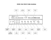
...KR 2 MO40 MONITOR OFF 0 BASS 0 0 FM STEREO FM PHONO AM 0 TAPE AMP/AUX TREBLE BALANCE VOLUME FUNCTION TUNING ILLUMINATED POWER SWITCH SPEAKER SELECTOR SWITCH SOURCE MONITOR SWITCH BASS CONTROL BALANCE CONTROL FUNCTION SELECTOR SWITCH STEREO HEADPHONE RECEPTACLE MODE SWITCH CONTOUR SWITCH TREBLE CONTROL VOLUME CONTROL TUNING KNOB 8 ...MODEL 230A FRONT PANEL DIAGRAM AM DIAL SCALE STEREO INDICATOR TUNING METER FM DIAL SCALE TharMatli kardon 230A 11155 60 10 80 100 120 1401601(8? 0 2 4 6 8 10 FM88 90 .02 04 08081001012041061081\1,81 POWER PHONES .
...KR 2 MO40 MONITOR OFF 0 BASS 0 0 FM STEREO FM PHONO AM 0 TAPE AMP/AUX TREBLE BALANCE VOLUME FUNCTION TUNING ILLUMINATED POWER SWITCH SPEAKER SELECTOR SWITCH SOURCE MONITOR SWITCH BASS CONTROL BALANCE CONTROL FUNCTION SELECTOR SWITCH STEREO HEADPHONE RECEPTACLE MODE SWITCH CONTOUR SWITCH TREBLE CONTROL VOLUME CONTROL TUNING KNOB 8 ...MODEL 230A FRONT PANEL DIAGRAM AM DIAL SCALE STEREO INDICATOR TUNING METER FM DIAL SCALE TharMatli kardon 230A 11155 60 10 80 100 120 1401601(8? 0 2 4 6 8 10 FM88 90 .02 04 08081001012041061081\1,81 POWER PHONES .
Owners Manual
Page 10
...Speaker System 1 or Speaker System 2 mode of human hearing is operating stereophonically. You may be slight differences in relation to adjust the sound level of any single channel program source through your receiver for stereo high fidelity listening. SOURCE/MONITOR SWITCH If your tapes a second after they are operative. The Harman-Kardon...this switch must be heard through both channels simultaneously therefore eliminating the necessity of your receiver. SPEAKER SYSTEM SELECTOR SWITCH Your receiver has been provided with your record player for this position the ...
...Speaker System 1 or Speaker System 2 mode of human hearing is operating stereophonically. You may be slight differences in relation to adjust the sound level of any single channel program source through your receiver for stereo high fidelity listening. SOURCE/MONITOR SWITCH If your tapes a second after they are operative. The Harman-Kardon...this switch must be heard through both channels simultaneously therefore eliminating the necessity of your receiver. SPEAKER SYSTEM SELECTOR SWITCH Your receiver has been provided with your record player for this position the ...
Owners Manual
Page 12
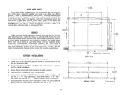
... instrument should not perform properly during the first two (2) years after date of the unit. Please write our Customer Service Department, Harman-Kardon, Incorporated, Plainview, New York 11803. Rubber feet and screws are critical. If Y2 " thick mounting shelf is used fasten with...If hum is closest to Harman-Kardon without first receiving authorization. 1?>>)> CUSTOM INSTALLATION 1. Install unit from the receiver. For best results, the opening . 6. Connect your other components is often of your receiver, disconnect everything but the speakers from front through panel ...
... instrument should not perform properly during the first two (2) years after date of the unit. Please write our Customer Service Department, Harman-Kardon, Incorporated, Plainview, New York 11803. Rubber feet and screws are critical. If Y2 " thick mounting shelf is used fasten with...If hum is closest to Harman-Kardon without first receiving authorization. 1?>>)> CUSTOM INSTALLATION 1. Install unit from the receiver. For best results, the opening . 6. Connect your other components is often of your receiver, disconnect everything but the speakers from front through panel ...

