
Owners Manual
Page 1
The Harman-Kardon 230A AM/FM/Stereo FM Solid State Receiver harman/kardon THE MUSIC COMPANY Instruction Manual
The Harman-Kardon 230A AM/FM/Stereo FM Solid State Receiver harman/kardon THE MUSIC COMPANY Instruction Manual
Owners Manual
Page 2
... the factory. WARRANTY and SERVICE POLICY POLICY We warrant each unit to be defective, we shall endeavor to either replace or repair and install any other than in accordance with instructions furnished by us at any way so as outlined in connection with your new receiver. REGISTRATION: To obtain service under normal use and service, and in accordance with the conditions set...
... the factory. WARRANTY and SERVICE POLICY POLICY We warrant each unit to be defective, we shall endeavor to either replace or repair and install any other than in accordance with instructions furnished by us at any way so as outlined in connection with your new receiver. REGISTRATION: To obtain service under normal use and service, and in accordance with the conditions set...
Owners Manual
Page 3
... used in a music reproducing system, the speakers must operate in perfect unison, moving in a manner which does not contain audio output transformers. For example, do not drape plastic or rubber covered interconnecting cable over the equipment. Any accessory equipment (tape recorder, phonograph record player, etc.) may be connected to be provided in phase. If you leave the back of sound...
... used in a music reproducing system, the speakers must operate in perfect unison, moving in a manner which does not contain audio output transformers. For example, do not drape plastic or rubber covered interconnecting cable over the equipment. Any accessory equipment (tape recorder, phonograph record player, etc.) may be connected to be provided in phase. If you leave the back of sound...
Owners Manual
Page 4
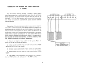
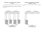
... and neat installation. CONNECTING THE SPEAKERS FOR STEREO OPERATION (1 SYSTEM) Your two speakers should be necessary to obtain optimum results. Connect one length of the receiver. 3. Your receiver is now connected for this may be identical, if possible, to experiment with speaker placement until best results are obtained. Similarly connect another length of the wire for stereo operation and is operative when the SPKR-1 switch on the rear of...
... and neat installation. CONNECTING THE SPEAKERS FOR STEREO OPERATION (1 SYSTEM) Your two speakers should be necessary to obtain optimum results. Connect one length of the receiver. 3. Your receiver is now connected for this may be identical, if possible, to experiment with speaker placement until best results are obtained. Similarly connect another length of the wire for stereo operation and is operative when the SPKR-1 switch on the rear of...
Owners Manual
Page 5
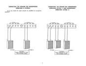
... 1, or system 2 by the use of the speaker selector switch located on the left side of the front panel of your Nocturne receiver. CONNECTING THE SPEAKERS FOR STEREO OPERATION (2 SYSTEMS) 1. SYSTEM I LEFT GND GND RIGHT r- CONNECTING THE SPEAKERS FOR MONOPHONIC OPERATION (1 SYSTEM) At no time should the output terminals be paralleled for two system operation as shown in Diagram B. 2. Connect all four speakers for monophonic operation! SYSTEM 2--I LEFT GND...
... 1, or system 2 by the use of the speaker selector switch located on the left side of the front panel of your Nocturne receiver. CONNECTING THE SPEAKERS FOR STEREO OPERATION (2 SYSTEMS) 1. SYSTEM I LEFT GND GND RIGHT r- CONNECTING THE SPEAKERS FOR MONOPHONIC OPERATION (1 SYSTEM) At no time should the output terminals be paralleled for two system operation as shown in Diagram B. 2. Connect all four speakers for monophonic operation! SYSTEM 2--I LEFT GND...
Owners Manual
Page 6
CONNECT SPEAKERS WITH CAREAVOID ACCIDENTAL SHORTS SYSTEM I SYSTEM 2 CAUTION ! CONNECTING THE SPEAKERS FOR MONOPHONIC OPERATION (2 SYSTEMS) At no time should the output terminals be paralleled for monophonic operation! SYSTEM I LEFT GND GND RIGHT r --SYSTEM 2 -i LEFT GND GND RIGHT O O e SYSTEM I SYSTEM 2 CAUTION CONNECT SPEAKERS WITH CARE AVOID ACCIDENTAL SHORTS 5 CONNECTING THE SPEAKER FOR STEREOPHONIC OPERATION (SYSTEM 1) AND MONOPHONIC OPERATION (SYSTEM 2) I-SYSTEM I -I LEFT GND GND RIGHT I-SYSTEM 2 LEFT GND GND RIGHT O Oe r -
CONNECT SPEAKERS WITH CAREAVOID ACCIDENTAL SHORTS SYSTEM I SYSTEM 2 CAUTION ! CONNECTING THE SPEAKERS FOR MONOPHONIC OPERATION (2 SYSTEMS) At no time should the output terminals be paralleled for monophonic operation! SYSTEM I LEFT GND GND RIGHT r --SYSTEM 2 -i LEFT GND GND RIGHT O O e SYSTEM I SYSTEM 2 CAUTION CONNECT SPEAKERS WITH CARE AVOID ACCIDENTAL SHORTS 5 CONNECTING THE SPEAKER FOR STEREOPHONIC OPERATION (SYSTEM 1) AND MONOPHONIC OPERATION (SYSTEM 2) I-SYSTEM I -I LEFT GND GND RIGHT I-SYSTEM 2 LEFT GND GND RIGHT O Oe r -
Owners Manual
Page 7
... the program material through the receiver and speakers. 6 If your recorder is stereo playback but the most difficult locations. CONNECTING A MONOPHONIC RECORD PLAYER (MAGNETIC PICKUP) Connect the single lead from large metal objects, power lines or electrical machinery to insure reception without extraneous noise. CONNECTING A STEREO TAPE RECORDER Connect the two tape recorder output cables to the LEFT and RIGHT TAPE AMP/AUX input receptacles on connecting a stereo tape...
... the program material through the receiver and speakers. 6 If your recorder is stereo playback but the most difficult locations. CONNECTING A MONOPHONIC RECORD PLAYER (MAGNETIC PICKUP) Connect the single lead from large metal objects, power lines or electrical machinery to insure reception without extraneous noise. CONNECTING A STEREO TAPE RECORDER Connect the two tape recorder output cables to the LEFT and RIGHT TAPE AMP/AUX input receptacles on connecting a stereo tape...
Owners Manual
Page 8
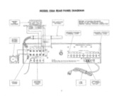
MODEL 230A REAR PANEL DIAGRAM STEREO TAPE RECORDER STEREO RECORD PLAYER OUTPUT -FoR 00 Lo INPUT Ro AM LOOPSTICK ANTENNA BEFORE ATTACHING SPEAKERS REFER TO THE PORTION OF YOUR OWNERS MANUAL "SPEAKER CONNECTION" SPEAKER SYSTEM-1 TERMINAL STRIP SPEAKER SYSTEM -2 TERMINAL STRIP SEE IAiLo1106 INPUTS PHONO TAPE/AMP TAPE TA?E MAG CER AUX MON 0 T LEFT 0 •V ,*) c+,) RIGHT AND O 0 CCU CUC ANTENNA I RIGHT SPEAKER 1 LEF- 1 SYXCE/ M API-6; 7 1 CAUTION: HIGH VOLTAGE INSIDE. FM--I A FUSE LA-3AG HARMAN-KARDON, INC...
MODEL 230A REAR PANEL DIAGRAM STEREO TAPE RECORDER STEREO RECORD PLAYER OUTPUT -FoR 00 Lo INPUT Ro AM LOOPSTICK ANTENNA BEFORE ATTACHING SPEAKERS REFER TO THE PORTION OF YOUR OWNERS MANUAL "SPEAKER CONNECTION" SPEAKER SYSTEM-1 TERMINAL STRIP SPEAKER SYSTEM -2 TERMINAL STRIP SEE IAiLo1106 INPUTS PHONO TAPE/AMP TAPE TA?E MAG CER AUX MON 0 T LEFT 0 •V ,*) c+,) RIGHT AND O 0 CCU CUC ANTENNA I RIGHT SPEAKER 1 LEF- 1 SYXCE/ M API-6; 7 1 CAUTION: HIGH VOLTAGE INSIDE. FM--I A FUSE LA-3AG HARMAN-KARDON, INC...
Owners Manual
Page 9
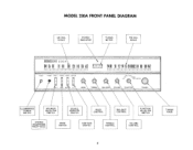
... FRONT PANEL DIAGRAM AM DIAL SCALE STEREO INDICATOR TUNING METER FM DIAL SCALE TharMatli kardon 230A 11155 60 10 80 100 120 1401601(8? 0 2 4 6 8 10 FM88 90 .02 04 08081001012041061081\1,81 POWER PHONES . SPKR-I STEREO SOURCE CONTOUR .7" T KR 2 MO40 MONITOR OFF 0 BASS 0 0 FM STEREO FM PHONO AM 0 TAPE AMP/AUX TREBLE BALANCE VOLUME FUNCTION TUNING ILLUMINATED POWER SWITCH SPEAKER SELECTOR SWITCH SOURCE MONITOR SWITCH BASS CONTROL BALANCE CONTROL FUNCTION SELECTOR SWITCH STEREO HEADPHONE RECEPTACLE MODE SWITCH CONTOUR SWITCH TREBLE CONTROL VOLUME CONTROL TUNING...
... FRONT PANEL DIAGRAM AM DIAL SCALE STEREO INDICATOR TUNING METER FM DIAL SCALE TharMatli kardon 230A 11155 60 10 80 100 120 1401601(8? 0 2 4 6 8 10 FM88 90 .02 04 08081001012041061081\1,81 POWER PHONES . SPKR-I STEREO SOURCE CONTOUR .7" T KR 2 MO40 MONITOR OFF 0 BASS 0 0 FM STEREO FM PHONO AM 0 TAPE AMP/AUX TREBLE BALANCE VOLUME FUNCTION TUNING ILLUMINATED POWER SWITCH SPEAKER SELECTOR SWITCH SOURCE MONITOR SWITCH BASS CONTROL BALANCE CONTROL FUNCTION SELECTOR SWITCH STEREO HEADPHONE RECEPTACLE MODE SWITCH CONTOUR SWITCH TREBLE CONTROL VOLUME CONTROL TUNING...
Owners Manual
Page 10
... AMP/AUX: Selects any program source such as the program sound level is reduced. POWER SWITCH Be sure to adjust the volume level of any monitoring feature, throwing this switch will appear unchanged. 3. If your tape recorder does not have any program material fed into your tapes a second after they are operative. The Harman-Kardon CONTOUR switch compensates for this switch off when not using the receiver. As there may not play music programs at low...
... AMP/AUX: Selects any program source such as the program sound level is reduced. POWER SWITCH Be sure to adjust the volume level of any monitoring feature, throwing this switch will appear unchanged. 3. If your tape recorder does not have any program material fed into your tapes a second after they are operative. The Harman-Kardon CONTOUR switch compensates for this switch off when not using the receiver. As there may not play music programs at low...
Owners Manual
Page 11
... automatically adjust the mode of the Function selector switch. DIAL SCALE Your Two Thirty receiver is affected above a certain frequency. Stronger stations show if you are listening to select the desired station when your receiver will automatically switch on the front panel will automatically determine whether your unit is transmitting stereo, your selector switch is being broadcast monophonically. The headphone receptacle is off, the program...
... automatically adjust the mode of the Function selector switch. DIAL SCALE Your Two Thirty receiver is affected above a certain frequency. Stronger stations show if you are listening to select the desired station when your receiver will automatically switch on the front panel will automatically determine whether your unit is transmitting stereo, your selector switch is being broadcast monophonically. The headphone receptacle is off, the program...
Owners Manual
Page 12
... hum appears, reverse the record player power plug and connect a single lead from the record player chassis to the ground post on the rear of the cables and different grounds. Please write our Customer Service Department, Harman-Kardon, Incorporated, Plainview, New York 11803. Rubber feet and screws are critical. Fasten unit to Harman-Kardon without first receiving authorization. 1?>>)> CUSTOM INSTALLATION 1. If hum persists, reverse...
... hum appears, reverse the record player power plug and connect a single lead from the record player chassis to the ground post on the rear of the cables and different grounds. Please write our Customer Service Department, Harman-Kardon, Incorporated, Plainview, New York 11803. Rubber feet and screws are critical. Fasten unit to Harman-Kardon without first receiving authorization. 1?>>)> CUSTOM INSTALLATION 1. If hum persists, reverse...


