

Owners Manual
Page 1
... your Harman-Kardon Model A-224 Stereophonic Amplifier. It is your assurance of -Z$ w .vwr ° tik r::•• 5",•,3 %1`..* fW fn ,•';'1 xM ;1, 4 • ft • INSTRUCTION MANUAL It is essential you will take time to read it simple to keep this instruction booklet carefully before installing your system. of superb stereo performance. This is important for the proper operation of...
... your Harman-Kardon Model A-224 Stereophonic Amplifier. It is your assurance of -Z$ w .vwr ° tik r::•• 5",•,3 %1`..* fW fn ,•';'1 xM ;1, 4 • ft • INSTRUCTION MANUAL It is essential you will take time to read it simple to keep this instruction booklet carefully before installing your system. of superb stereo performance. This is important for the proper operation of...

Owners Manual
Page 2
... and workmanship under normal use and service, and in accordance with the conditions herein below set forth, for reference and should contain the following ways. 1-Stereophonic amplifier with 12 watts of audio in each Trio Model A-224 to be free from date of delivery to the original purchaser, and agree to replace or repair any part or parts, with the exception...
... and workmanship under normal use and service, and in accordance with the conditions herein below set forth, for reference and should contain the following ways. 1-Stereophonic amplifier with 12 watts of audio in each Trio Model A-224 to be free from date of delivery to the original purchaser, and agree to replace or repair any part or parts, with the exception...

Owners Manual
Page 3
... at the factory and should be those marked with speaker placement until best results are inoperative for an inconspicuous and neat installation. NOTE: A and B terminals on the rear of stereo speaker connection. (See Diagram A) The output terminals used should be allowed around the molding for this method of the instrument. REAR PANEL CONNECTIONS LOILI W0 PHONO TAPE [ EQUALIZATION LEFT RIGHT LEVEL INPUT HIGH LEVEL INPUT TAPE HI AUX 0 0 TUNER 0 PHONO 0 HI •...
... at the factory and should be those marked with speaker placement until best results are inoperative for an inconspicuous and neat installation. NOTE: A and B terminals on the rear of stereo speaker connection. (See Diagram A) The output terminals used should be allowed around the molding for this method of the instrument. REAR PANEL CONNECTIONS LOILI W0 PHONO TAPE [ EQUALIZATION LEFT RIGHT LEVEL INPUT HIGH LEVEL INPUT TAPE HI AUX 0 0 TUNER 0 PHONO 0 HI •...
Owners Manual
Page 4
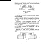
... 32 LEFT SPEAKER NORMAL STEREO SPEAKER HOOK UP Diagram A RIGHT SPEAKER Two Independent Stereo Speaker Systems: The Model A-224 stereo amplifier incorporates a unique switching arrangement enabling the user to operate two independent stereo speaker systems located in System B to the left of the pilot light must remain in the "SEPARATE" position. This complete System A installation. To install System B connect a lead from the left speaker to the 16 ohm terminal on the LEFT SPEAKER output strip...
... 32 LEFT SPEAKER NORMAL STEREO SPEAKER HOOK UP Diagram A RIGHT SPEAKER Two Independent Stereo Speaker Systems: The Model A-224 stereo amplifier incorporates a unique switching arrangement enabling the user to operate two independent stereo speaker systems located in System B to the left of the pilot light must remain in the "SEPARATE" position. This complete System A installation. To install System B connect a lead from the left speaker to the 16 ohm terminal on the LEFT SPEAKER output strip...

Owners Manual
Page 5
... cord of your Harman-Kardon stereo tuner should be connected to the RIGHT HIGH LEVEL INPUT jack. Stereo crystal or ceramic cartridges may be connected to the LEFT LOW LEVEL INPUT jack located on the lower rear of the chassis, and the other into the TAPE-III/AUX jack on the lower left preamplifier channel, use , either LEFT or RIGHT TAPE OUT receptacle. Place both types of program sources are desired, it...
... cord of your Harman-Kardon stereo tuner should be connected to the RIGHT HIGH LEVEL INPUT jack. Stereo crystal or ceramic cartridges may be connected to the LEFT LOW LEVEL INPUT jack located on the lower rear of the chassis, and the other into the TAPE-III/AUX jack on the lower left preamplifier channel, use , either LEFT or RIGHT TAPE OUT receptacle. Place both types of program sources are desired, it...

Owners Manual
Page 6
... the bass and treble tones of faithfulness and spatial distribution. Sufficient range is available, and monaural operation utilizing the full power of any program material fed into your hearing preference, speaker characteristics and room acoustics. When the BALANCE control is such that this control will be doubled. Viewing the instrument from fine modern recordings. This would normally be set , the apparent sound source will...
... the bass and treble tones of faithfulness and spatial distribution. Sufficient range is available, and monaural operation utilizing the full power of any program material fed into your hearing preference, speaker characteristics and room acoustics. When the BALANCE control is such that this control will be doubled. Viewing the instrument from fine modern recordings. This would normally be set , the apparent sound source will...

Owners Manual
Page 7
... controls can be used for proper tone equalization. Connecting Your Tape Player: Connect your high fidelity system. Connecting Your Tape Recorder To Make A Recording: Provision is plugged into the right preamplifier channel, use the LEFT TAPE OUT jack and if it into either LEFT or RIGHT TAPE-HI/AUX jack on the rear panel. If the program source you will note a TREBLE Control (on/off switch is connected to the LEFT LOW LEVEL INPUT, connect...
... controls can be used for proper tone equalization. Connecting Your Tape Player: Connect your high fidelity system. Connecting Your Tape Recorder To Make A Recording: Provision is plugged into the right preamplifier channel, use the LEFT TAPE OUT jack and if it into either LEFT or RIGHT TAPE-HI/AUX jack on the rear panel. If the program source you will note a TREBLE Control (on/off switch is connected to the LEFT LOW LEVEL INPUT, connect...

Owners Manual
Page 8
... "ON". The Harman-Kardon CONTOUR Switch compensates for the Fletcher-Munson effect, thus eliminating high listening levels as "Rumble", this preamplifier. For low level listening throw the CONTOUR Switch located on the front panel to experience the full rich tone available from fine modern recordings. Mode Switch: The only application for double the usual number of input jacks found on ordinary monaural amplifiers. STEREO REVERSE and MONAURAL...
... "ON". The Harman-Kardon CONTOUR Switch compensates for the Fletcher-Munson effect, thus eliminating high listening levels as "Rumble", this preamplifier. For low level listening throw the CONTOUR Switch located on the front panel to experience the full rich tone available from fine modern recordings. Mode Switch: The only application for double the usual number of input jacks found on ordinary monaural amplifiers. STEREO REVERSE and MONAURAL...

Owners Manual
Page 9
... player power plug, and try connecting a wire from the amplifier, and listen for absolute minimum distortion. Play a stereo record or tape and turn . Now, while listening carefully to the left and right channels. Program sources such as a normal stereo amplifier. Each operates simultaneously to adjust both left speaker, adjust the LEFT OUTPUT BALANCE control for minimum hum, set , however, and then left permanently in that hum may be caused by interconnecting cables...
... player power plug, and try connecting a wire from the amplifier, and listen for absolute minimum distortion. Play a stereo record or tape and turn . Now, while listening carefully to the left and right channels. Program sources such as a normal stereo amplifier. Each operates simultaneously to adjust both left speaker, adjust the LEFT OUTPUT BALANCE control for minimum hum, set , however, and then left permanently in that hum may be caused by interconnecting cables...

Owners Manual
Page 10
... SPEAKER RIGHT SPEAKER HOOK UP FOR STEREO CONVERSION Diagram E Connecting Both Amplifiers For Stereo Operation: G 8 16 SPEAKER Connect a shielded lead not longer than 3 or 4 feet between the LEFT PREAMP OUT jack on your other amplifier. INSTALLATION PROCEDURE Connecting Your Speakers: Your two speakers should be matched if possible to obtain optimum results and should be placed 8 to 15 feet apart against one wall of the A-224 and the Aux or Tuner input...
... SPEAKER RIGHT SPEAKER HOOK UP FOR STEREO CONVERSION Diagram E Connecting Both Amplifiers For Stereo Operation: G 8 16 SPEAKER Connect a shielded lead not longer than 3 or 4 feet between the LEFT PREAMP OUT jack on your other amplifier. INSTALLATION PROCEDURE Connecting Your Speakers: Your two speakers should be matched if possible to obtain optimum results and should be placed 8 to 15 feet apart against one wall of the A-224 and the Aux or Tuner input...


